1
ADL 1000-5100 Large AP-1 Control Dehumidifying Dryer Part Number: 882.00203.00 Bulletin Number: DH1-615-1 Effective: 09/13/2007 Write Down Your Serial Numbers Here For Future Reference: _________________________ _________________________ _________________________ _________________________ _________________________ _________________________ We are committed to a continuing program of product improvement. Specifications, appearance, and dimensions described in this manual are subject to change without notice. DCN No. ____________ © Copyright 2008 All rights reserved. Shipping Info Unpacking and Inspection You should inspect the large dehumidifying dryer for possible shipping damage. Thoroughly check the equipment for any damage that might have occurred in transit, such as broken or loose wiring and components, loose hardware and mounting screws, etc. In the Event of Shipping Damage According to the contract terms and conditions of the Carrier, the responsibility of the Shipper ends at the time and place of shipment. Notify the transportation company’s local agent if you discover damage. Hold the damaged goods and packing material for the examining agent’s inspection. Do not return any goods before the transportation company’s inspection and authorization. File a claim with the transportation company. Substantiate the claim by referring to the agent’s report. A certified copy of our invoice is available upon request. The original Bill of Lading is attached to our original invoice. If the shipment was prepaid, write us for a receipted transportation bill. Advise customer service regarding your wish for assistance and to obtain an RMA (return material authorization) number. If the Shipment is Not Complete Check the packing list as back-ordered items are noted on the packing list. You should have: ; Large Dehumidifying Dryer ; Bill of lading ; Packing list ; Operating and Installation packet ; Electrical schematic and panel layout drawings ; Component instruction manuals Re-inspect the container and packing material to see if you missed any smaller items during unpacking. If the Shipment is Not Correct If the shipment is not what you ordered, contact the parts and service department immediately at [847] 273-7700. Have the item and order numbers ready. Hold the items until you receive shipping instructions. Large Dehumidifying Dryers ii Returns Do not return any damaged or incorrect items until you receive shipping instructions from the shipping department. Credit Returns Prior to the return of any material authorization must be given by the manufacturer. A RMA number will be assigned for the equipment to be returned. Reason for requesting the return must be given. ALL returned material purchased from the manufacturer returned is subject to 15% ($75.00 minimum) restocking charge. ALL returns are to be shipped prepaid. The invoice number and date or purchase order number and date must be supplied. No credit will be issued for material that is not within the manufacturer’s warranty period and/or in new and unused condition, suitable for resale. Warranty Returns Prior to the return of any material, authorization must be given by the manufacturer. A RMA number will be assigned for the equipment to be returned. Reason for requesting the return must be given. All returns are to be shipped prepaid. The invoice number and date or purchase order number and date must be supplied. After inspecting the material, a replacement or credit will be given, at the manufacturer’s discretion. If the item is found to be defective in materials or workmanship, and it was manufactured by our company, purchased components are covered under their specific warranty terms. Large Dehumidifying Dryers iii Table of Contents CHAPTER 1: SAFETY................................................................ 7 1-1 1-2 1-3 How to Use This Manual ............................................................................................. 7 Safety Symbols Used in this Manual .....................................................................7 Warnings and Precautions .......................................................................................... 8 Responsibility .............................................................................................................. 9 General Responsibility...........................................................................................9 Operator Responsibility .........................................................................................9 Maintenance Responsibility.................................................................................10 Reporting a Safety Defect ...................................................................................11 CHAPTER 2: FUNCTIONAL DESCRIPTION ........................... 12 2-1 2-2 2-3 2-4 2-5 2-6 Models Covered in This Manual................................................................................ 12 General Description................................................................................................... 12 Specifying a Drying System ................................................................................12 What is Desiccant?..............................................................................................12 The Closed Loop Drying System.........................................................................12 The Process/Regeneration Cycle........................................................................13 Sequence of Operation .......................................................................................13 Standard Features..................................................................................................... 14 Auto Start Timer ..................................................................................................14 Mechanical Features ...........................................................................................14 Electrical Features...............................................................................................14 Options ...................................................................................................................... 15 Dewpoint Extend .................................................................................................15 Closed-Loop Regeneration .................................................................................15 Drawings and Diagrams ............................................................................................ 16 Process Aftercooler .............................................................................................18 Aftercooler Design Specifications........................................................................18 Process Air Dust Collector...................................................................................18 Material Overdrying Protection ............................................................................20 Mechanical Options .............................................................................................21 Electrical Options ................................................................................................21 Controller Options ...............................................................................................21 Safety Devices and Interlocks ................................................................................... 22 Dimensions and Specifications 9 Denotes availability..................................24 Mechanical Options 9 Denotes availability ..................................................24 Electrical Features...............................................................................................25 Electrical Options ................................................................................................25 CHAPTER 3: MECHANICAL INSTALLATION ........................ 26 3-1 3-2 3-3 3-4 3-5 3-6 Uncrating the Equipment........................................................................................... 26 Rigging and Placing Unit ........................................................................................... 26 Making Electrical Connections .................................................................................. 26 Making Gas Line Connections (Gas-Fired Models Only) .......................................... 27 Checking for Proper Blower Rotation ........................................................................ 28 Making Dryer/Drying Hopper Process Air Connections ............................................ 29 Large Dehumidifying Dryers iv 3-7 3-8 Connecting Aftercooler/Precooler Cooling Water (Optional)..................................... 32 Using the Drying Hopper Air Trap ............................................................................. 33 CHAPTER 4: CONTROLS........................................................ 34 4-1 4-2 4-3 Controller Description................................................................................................ 34 Identifying Control Panel Components for the AP-1 Optional Controller................ 35 Disconnect Switch ...............................................................................................35 Control Power Switch ..........................................................................................35 Touch Screen ......................................................................................................35 Alarm Horn & Light ..............................................................................................35 Process Air Temperature and Conveying Process Controller................................... 35 ...................................................................35 4-4 Identifying Controller Screens ................................................................................... 36 Main Menu Screen............................................................................................................... 36 Typical Dryer Screens.......................................................................................................... 36 System Screens ..................................................................................................43 Alarm Screens .....................................................................................................48 Alarm Screen Example........................................................................................49 See Section 7-4: Alarms on p. 57 for alarm descriptions. ............................................................ 49 4-5 Redundant Safety Controller Display ........................................................................ 49 4-6 Setting the Redundant Safety Controller................................................................... 50 CHAPTER 5: OPERATION....................................................... 52 5-1 5-2 5-3 Start-up...................................................................................................................... 52 Using the Dryer Status Screen.................................................................................. 53 Alarms ....................................................................................................................... 54 5-4 5-5 ................................................................................ 54 Alarm Descriptions .................................................................................................... 54 Shutdown .................................................................................................................. 55 CHAPTER 6: MAINTENANCE ................................................. 56 6-1 6-2 6-3 Maintenance Schedule.............................................................................................. 56 Preventative Maintenance......................................................................................... 57 Cleaning or Replacing the Process Air Filters .....................................................57 Cleaning or Replacing the Regeneration Filter....................................................58 Calibrating the Dirty Filter Alarm..........................................................................58 Checking the Dewpoint Control System ..............................................................59 Corrective Maintenance ............................................................................................ 60 Symptoms of Worn Out Desiccant ......................................................................60 Replacing the Desiccant......................................................................................60 Replacing the Process Heater (Electric Dryers) ..................................................61 Large Dehumidifying Dryers v Replacing the Regeneration Heater (Electric Dryers) .........................................62 CHAPTER 7: TROUBLESHOOTING ....................................... 64 7-1 7-2 7-3 Introduction................................................................................................................ 64 Basic Troubleshooting............................................................................................... 64 Determining Temperature Controller Errors or Sensor Errors................................... 66 Using a Thermocouple ........................................................................................66 Using a Platinum Resistance Thermometer ........................................................66 CHAPTER 8: APPENDIX.......................................................... 67 8-1 8-2 8-3 8-4 Technical Specifications............................................................................................ 67 Annex B Information ............................................................................................67 Spare Parts List......................................................................................................... 68 8-5 Dryer Identification (Serial Number) Tag............................................................. 70 Technical Assistance................................................................................................. 71 Parts Department ................................................................................................71 Service Department.............................................................................................71 Sales Department................................................................................................71 Contract Department ...........................................................................................71 Large Dehumidifying Dryers vi Chapter 1: Safety 1-1 How to Use This Manual Use this manual as a guide and reference for installing, operating, and maintaining the large dehumidifying dryer. The purpose is to assist you in applying efficient, proven techniques that enhance equipment productivity. This manual covers only light corrective maintenance. No other maintenance should be undertaken without first contacting a service engineer. The Functional Description section outlines models covered, standard features, and safety features. Additional sections within the manual provide instructions for installation, preoperational procedures, operation, preventive maintenance, and corrective maintenance. The Installation chapter includes required data for receiving, unpacking, inspecting, and setup of the large dehumidifying dryer. We can also provide the assistance of a factory-trained technician to help train your operator(s) for a nominal charge. This section includes instructions, checks, and adjustments that should be followed before commencing with operation of the dryer. These instructions are intended to supplement standard shop procedures performed at shift, daily, and weekly intervals. The Operation chapter includes a description of electrical and mechanical controls, in addition to information for operating the dryer safely and efficiently. The Maintenance chapter is intended to serve as a source of detailed assembly and disassembly instructions for those areas of the equipment requiring service. Preventive maintenance sections are included to ensure that the dehumidifying dryer provides excellent, long service. The Troubleshooting chapter serves as a guide for identification of most common problems. Potential problems are listed, along with possible causes and related solutions. The Appendix contains technical specifications, drawings, schematics, parts lists, and available options. A spare parts list with part numbers specific to your machine is provided with your shipping paperwork package. Refer to this section for a listing of spare parts for purchase. Have your serial number and model number ready when ordering. Safety Symbols Used in this Manual The following safety alert symbols are used to alert you to potential personal injury hazards. Obey all safety messages that follow these symbols to avoid possible injury or death. DANGER! DANGER indicates an imminently hazardous situation that, if not avoided, will result in death or serious injury. WARNING! WARNING indicates a potentially hazardous situation or practice that, if not avoided, could result in death or serious injury. Caution! CAUTION indicates a potentially hazardous situation or practice that, if not avoided, may result in minor or moderate injury or in property damage. Large Dehumidifying Dryers Safety 7 Dryer Safety Tags Tag Description Tag Read Operation & Installation Manual PE 1-2 Description High Voltage Inside Enclosure Hot! Lifting Point Protected Earth Ground Earth Ground Warnings and Precautions Our equipment is designed to provide safe and reliable operation when installed and operated within design specifications, following national and local safety codes. This may include, but is not limited to OSHA, NEC, CSA, SPI, and any other local, national and international regulations. To avoid possible personal injury or equipment damage when installing, operating, or maintaining this equipment, use good judgment and follow these safe practices: ; Read and follow these operation and installation instructions when installing, operating, and maintaining this equipment. If these instructions become damaged or unreadable, additional copies are available from the manufacturer. ; Follow all SAFETY CODES. ; Wear SAFETY GLASSES and WORK GLOVES. ; Work only with approved tools and devices. ; Disconnect and/or lock out power before servicing or maintaining the equipment. ; Use care when LOADING, UNLOADING, RIGGING, or MOVING this equipment. ; Operate this equipment within design specifications. ; OPEN, TAG, and LOCK ALL DISCONNECTS before working on equipment. You should remove the fuses and carry them with you. ; Make sure the equipment and components are properly GROUNDED before you switch on power. ; When welding or brazing in or around this equipment, make sure VENTILATION is ADEQUATE. PROTECT adjacent materials from flame or sparks by shielding with sheet metal. An approved FIRE EXTINGUISHER should be nearby and ready for use if needed. ; Do not restore power until you remove all tools, test equipment, etc., and the equipment and related components are fully reassembled. Large Dehumidifying Dryers Safety 8 ; Only PROPERLY TRAINED personnel familiar with the information in this manual should work on this equipment. We have long recognized the importance of safety and have designed and manufactured our equipment with operator safety as a prime consideration. We expect you, as a user, to abide by the foregoing recommendations in order to make operator safety a reality. 1-3 Responsibility These machines are constructed for maximum operator safety when used under standard operating conditions and when recommended instructions are followed in the maintenance and operation of the machine. All personnel engaged in the use of the machines should become familiar with their operation as described in this manual. Proper operation of the machine promotes safety for the operator and all workers in its vicinity. Each individual must take responsibility for observing the prescribed safety rules as outlined. All warning and danger signs must be observed and obeyed. All actual or potential danger areas must be reported to your immediate supervisor. General Responsibility No matter who you are, safety is important. Owners, operators and maintenance personnel must realize that every day, safety is a vital part of their jobs. If your main concern is loss of productivity, remember that production is always affected in a negative way following an accident. The following are some of the ways that accidents can affect your production: • Loss of a skilled operator (temporarily or permanently) • Breakdown of shop morale • Costly damage to equipment • Downtime An effective safety program is responsible and economically sound. Organize a safety committee or group, and hold regular meetings. Promote this group from the management level. Through this group, the safety program can be continually reviewed, maintained, and improved. Keep minutes or a record of the meetings. Hold daily equipment inspections in addition to regular maintenance checks. You will keep your equipment safe for production and exhibit your commitment to safety. Please read and use this manual as a guide to equipment safety. This manual contains safety warnings throughout, specific to each function and point of operation. Operator Responsibility The operator’s responsibility does not end with efficient production. The operator usually has the most daily contact with the equipment and intimately knows its capabilities and limitations. Plant and personnel safety is sometimes forgotten in the desire to meet incentive rates, or through a casual attitude toward machinery formed over a period of months or years. Your Large Dehumidifying Dryers Safety 9 employer probably has established a set of safety rules in your workplace. Those rules, this manual, or any other safety information will not keep you from being injured while operating your equipment. Learn and always use safe operation. Cooperate with co-workers to promote safe practices. Immediately report any potentially dangerous situation to your supervisor. ; NEVER place your hands or any part of your body in any dangerous location. ; NEVER operate, service, or adjust the dryer without appropriate training and first reading and understanding this manual. ; NEVER try to pull material out of the dryer with your hands while it is running! ; Before you start the dehumidifying dryer, check the following: • Remove all tools from the dryer; • Be sure no objects (tools, nuts, bolts, clamps, bars) are laying in the area; ; If your dryer has been inoperative or unattended, check all settings before starting. ; At the beginning of your shift and after breaks, verify that the controls and other auxiliary equipment are functioning properly. ; Keep all safety guards in place and in good repair. NEVER attempt to bypass, modify, or remove safety guards. Such alteration is not only unsafe, but will void the warranty on your equipment. ; When changing control settings to perform a different mode of operation, be sure selector switches are correctly positioned. Locking selector switches should only be adjusted by authorized personnel and the keys removed after setting. ; Report the following occurrences IMMEDIATELY: • • • • • unsafe operation or condition unusual dryer action leakage improper maintenance NEVER stand or sit where you could slip or stumble into the dehumidifying dryer while working on it. ; DO NOT wear loose clothing or jewelry, which can be caught while working on the dryer. In addition, cover or tie back long hair. ; Clean the dehumidifying dryer and surrounding area DAILY, and inspect the machine for loose, missing or broken parts. ; Shut off power to the dryer when it is not in use. Turn the switch to the OFF position, or unplug it from the power source. Maintenance Responsibility Proper maintenance is essential to safety. If you are a maintenance worker, you must make safety a priority to effectively repair and maintain equipment. Before removing, adjusting, or replacing parts on a machine, remember to turn off all electric supplies and all accessory equipment at the machine, and disconnect and lockout electrical and pneumatic power. Attach warning tags to the disconnect switch and air shutoff valve. Large Dehumidifying Dryers Safety 10 When you need to perform maintenance or repair work on a dehumidifying dryer above floor level, use a solid platform or a hydraulic elevator. If there is a permanently installed catwalk on your dryer, use it. The work platform should have secure footing and a place for tools and parts. DO NOT climb on the dehumidifying dryer, machines, or work from ladders. If you need to repair a large component, use appropriate handling equipment. Before you use handling equipment (portable “A” frames, electric boom trucks, fork trucks, overhead cranes) be sure the load does not exceed the capacity of the handling equipment or cause it to become unstable. Carefully test the condition of lifting cables, chains, ropes, slings, and hooks before using them to lift a load. Be sure that all non-current carrying parts are correctly connected to earth ground with an electrical conductor that complies with current codes. Install in accordance with national and local codes. When you have completed the repair or maintenance procedure, check your work and remove your tools, rigging, and handling equipment. Do not restore power to the dehumidifying dryer until all persons are clear of the area. DO NOT start and run the dryer until you are sure all parts are functioning correctly. BEFORE you turn the dehumidifying dryer over to the operator for production, verify all enclosure panels, guards and safety devices are in place and functioning properly. Reporting a Safety Defect If you believe that your equipment has a defect that could cause injury, you should immediately discontinue its use and inform the manufacturer. The principle factors that can result in injury are failure to follow proper operating procedures (i.e. lockout/tagout), or failure to maintain a clean and safe working environment. Large Dehumidifying Dryers Safety 11 Chapter 2: Functional Description 2-1 Models Covered in This Manual This manual provides operation, installation, and maintenance instructions for 600-3000 cfm Large Dehumidifying Dryers with AP1 control. These dryers are available with electric heaters or gas burners. Gas dryers are indicated with a “G” in the model number. Model numbers are listed on the serial tag. Make sure you know the model and serial number of your equipment before contacting the manufacturer for parts or service. Our dehumidifying dryers are designed to generate heated, dehumidified air at carefully controlled temperatures for use in closed-loop plastic drying systems. Dehumidifying dryers are sized to meet the specific requirements stated by the Customer at the time of purchase. 2-2 General Description Moisture removal from hygroscopic (moisture attracting) plastic pellets is an essential step in the manufacture of high-quality plastic products. Our Dehumidifying Dryers are used by the plastics industry to generate very low dewpoint air that is heated to a controlled temperature for drying plastic pellets and regrind. The drying system consists of a dry air source and drying hoppers with process heating controls. The dry air source controls two primary sub-systems, the process air and the regeneration circuit. Each dryer has a left and a right desiccant bed so that one bed can regenerate while the other is in use. 2000-3000 cfm dryers feature two sets of desiccant beds, for a total of four desiccant beds. The drying system can be configured for one drying hopper or for as many as 20 hoppers. The process air heater can be located on the dryer or on each individual drying hopper. Heaters that are located on the drying hoppers can be set up with their own independent controls or can be controlled centrally using the main dryer controller. Specifying a Drying System There were many variables considered in the selection of your drying system, including: type of materials, residence time, throughput of the extruder or injection molding machine, ambient air moisture and temperature, and the altitude at the processing site. Should your operating environment change, we can advise you on necessary equipment, process time and temperature modifications. What is Desiccant? Desiccant is a material that attracts and holds (absorbs) water from the air. The desiccant our dryers use is a synthetic crystalline metal aluminosilicate that is blended with a clay binder and formed into beads. Absorbed water is driven from saturated desiccant by heating it to a high temperature (reducing the desiccant's capacity to hold water) and forcing air through it. This moisture removal process is called "regeneration". The Closed Loop Drying System These dehumidifying dryers force hot, dry air through the resin in the drying hopper, where the air picks up moisture from the material and is drawn back to the dryer. In the dryer, Large Dehumidifying Dryers Functional Description 12 moisture is stripped from the air by a desiccant bed. The dried process air is then re-heated and delivered back into the drying hopper to dry material again. This system is a "closed loop", because ambient (outside) air is never introduced into the process air. The closed loop system is used by the manufacturer because the process air is typically much drier than ambient air, even after carrying moisture out of the plastic resin. Recycling process air maintains drying efficiency at a consistently high level. The Process/Regeneration Cycle There are two desiccant beds in a dryer up to 1500 cfm. Larger dryers have four beds (two left and two right beds). While one desiccant bed is on-line in the process air loop, the other is off-line being regenerated (see Figure 1). When a desiccant bed is on-line, it absorbs moisture from the process air. The desiccant will become saturated with moisture and need to be regenerated. The dryer automatically redirects the process airflow to the second bed and starts regenerating the first bed. During regeneration, air is heated to approximately 550°F and forced through the saturated desiccant. The moisture driven off the desiccant is bled to the atmosphere. The regeneration heater is then turned off while the regeneration blower continues to blow air through the desiccant bed until it is cooled. Figure 1: Regeneration Cycle AD600-AD1500 Dryer Flow Schematic Right Desiccant in Regeneration AD600-AD1500 Dryer Flow Schematic Left Desiccant in Regeneration Regeneration Blower Regeneration Filter Dryer Valve Regeneration Heaters Left Desiccant Regeneration Heaters Process Heater Regeneration Exhaust Regeneration Blower Regeneration Filter Dryer Valve Insulated Drying Hopper Process Filter Right Desiccant Process Heater Regeneration Exhaust Left Desiccant Process Blower Insulated Drying Hopper Process Filter Right Desiccant Process Blower Sequence of Operation When the dryer is started, the main air valve rotates 360º and then moves to place the last successfully regenerated desiccant bed online. If the dryer was powered off using the main power disconnect or E-stopped, then the regenerating bed is placed back into regeneration, and the regeneration cycle is started over. The main air valve is allowed a period of time to move from one position to the other. If the main air valve does not complete positioning within the allotted time, then a “Main Air Valve Fail” alarm is generated and the dryer stops the process air blower and disables the drying hoppers and regeneration circuit. If the closed loop regeneration option is enabled, the regeneration closed loop valve moves to the open loop position. The system always begins the cooling phase for a regeneration cycle using ambient (open loop) air. The closed loop regeneration valve is allowed a period of time to move from the closed to the open loop position and a “Closed Loop Valve” alarm is generated if the valve fails to reach the commanded position within this time. This alarm will disable the regeneration circuit but does not stop the process air system or drying hoppers. Large Dehumidifying Dryers Functional Description 13 Once the main air valve and closed loop regeneration valve are in place, the process air blower starts. The system monitors the process air blower’s overload, starter auxiliary contact feedback and air pressure. Loss of any of these items when the process air blower is running will cause the process air blower and the drying hopper’s process heaters to shut down. The process air heaters (or gas burners, on gas-fired dryers) will turn on after a delay to allow the process air blower to accelerate the operating speed. During normal operation, one set of desiccant beds is connected to the process air circuit while the other set is being regenerated. When the offline beds are done regenerating, they will be switched into the process air circuit and the other beds will be regenerated. The default bed switch setting is based on time. If the Dewpoint Switch option is enabled, the beds will switch when the process air dewpoint reaches the dewpoint switch point. The dewpoint option will automatically disable itself and an alarm will be generated if the dewpoint sensor or related electronics fail. 2-3 Standard Features Auto Start Timer The autostart timer is used to automatically start and stop the dryer at the time you specify. It can be programmed for one start and/or stop event per day for a week. When the Auto Start Timer is enabled, the dryer will automatically start and stop at pre-programmed times. If the dryer is stopped due to the Auto Start Timer, the DRYER STATUS message will indicate that the Auto Start timer is active. Mechanical Features ; 180ºF – 250ºF Drying temperature range ; High regeneration temperature control safeties ; 13X desiccant (molecular sieve) ; Easy to access process, regeneration, and combustion air filters. ; High pressure centrifugal blower ; Dew point +15º F to –40º F Electrical Features ; Electrically-actuated air valve ; NFPA79, UL & CUL machinery electrical standards (Electric Dryers) includes: Large Dehumidifying Dryers • NEMA 12 controls, components & enclosure • Non-fused electrical disconnect • Solid state relays for heater control • Branch fusing • Lockable power disconnects • Regeneration temperature control • “Process high temp” indication light and audible alarm • 7 day timer Functional Description 14 • Sequence shutdown switch ; NFPA86, UL, AGA & CGA machinery electrical standards (Gas Dryers) ; Available supply voltages of 208, 230, 460, 575/3/60 and 400/3/60 2-4 Options Dewpoint Extend The Dewpoint Extend option measures the temperature of the moist air as it is bled to the atmosphere after regeneration. After a period of time, the bleed temperature will rise. This condition, called "bed breakthrough" indicates that the bed is dry. At bed breakthrough, the bleed air temperature peaks between 350°F and 400°F. The regeneration heaters turn off automatically on bed breakthrough for additional energy savings. A 550°F regeneration temperature will dry the desiccant beds sufficiently to produce process air dewpoint of -40°F. In a properly sized system, this ultra-low humidity level will be more than adequate to dry plastics to as little as .003% moisture. Closed-Loop Regeneration An optional regeneration closed-loop valve and heat exchanger can be used to close the regeneration loop during the cooling portion of the regeneration cycle. If this option is enabled on the dryer, air will be bled to the atmosphere until the heating portion of the regeneration cycle is finished. Then, the regeneration closed loop valve will direct air through a water-cooled heat exchanger and back into the regeneration loop (see Figure 2). Figure 2: Closed Loop Regeneration Regeneration Blower Regeneration Blower AD600-AD1500 Dryer Flow Schematic Dryer Valve Regeneration Closed Loop Cooling is Activated Regeneration Heaters Regeneration Filter AD600-AD1500 Dryer Flow Schematic Regeneration Heating is Activated Optional Regeneration Closed Loop Cooler Regeneration Heaters Regenerarion Exhaust Regeneration Filter Optional Regeneration Closed Loop Cooler Regeneration Exhaust Optional Regeneration Closed Loop Valve Optional Regeneration Closed Loop Valve Left Desiccant Left Desiccant Large Dehumidifying Dryers Dryer Valve Functional Description 15 2-5 Drawings and Diagrams Regeneration Blower Insulated Drying Hopper Regen. Filter Process Air Filter Process Heater Optional Regeneration Closed Loop Cooler Regen. Optional Regeneration Exhaust Closed Loop Valve Optional After-cooler Right Desiccants Left Desiccants Dryer Valve Process Blower Airflow Schematic: 2000-3000 cfm dryers (4 desiccant beds). Left desiccant beds are regenerating—closed loop regeneration is activated. Regeneration Blower Insulated Drying Hopper Regen. Filter Process Air Filter Process Heater Optional Regeneration Closed Loop Cooler Regen. Optional Regeneration Exhaust Closed Loop Valve Optional After-cooler Right Desiccants Left Desiccants Dryer Valve Process Blower Airflow Schematic: 2000-3000 cfm dryers (4 desiccant bed). Left desiccant beds are regenerating in open-loop regeneration mode. Large Dehumidifying Dryers Functional Description 16 Filter Check Gage Differential Pressure Switch Thumb Screws PS Cartridge Filter Dust Shroud Filter Retainer F Slide Gate E Clamp Dust Level Indicator Dust Pan Optional dryer dust collector Large Dehumidifying Dryers Functional Description 17 Process Aftercooler The optional aftercooler cools the moist air returning to the dryer from the drying hopper. The aftercooler can cool the return air from 250ºF to about 150ºF. This maintains the dryer’s efficiency and condenses the unwanted plasticizer from the air stream. The aftercooler requires a cooling water connection (see Figure and page 25). Figure 3: Process Aftercooler Mounting Brackets High Temperature Gasket Mounting Brackets Cooling Coil Cooling Coil Pipe Gasket Stainless Steel Cooler Housing Stainless Steel Cooler Housing High Temperature Gasket Cooling Coil Cooling Coil Cover Plate Cooling Coil Pipe Gasket Cooling Coil Cover Plate Aftercooler Design Specifications Entering water temp. ºF 85ºF ºC 29ºC Process Air Dust Collector The optional process air dust collector consists of a filter, dust can, pressure gauge, and optional pressure switch (see Figure). The gauge will let you know whether it is time to clean out your filters. The optional dirty filter alarm will be activated if the filter is dirty. Large Dehumidifying Dryers Functional Description 18 Figure 4: Process Air Dust Collector Filter Check Gage Differential Pressure Switch Thumb Screws PS Cartridge Filter Dust Shroud Filter Retainer F Slide Gate E Clamp Dust Level Indicator Large Dehumidifying Dryers Dust Pan Functional Description 19 Material Overdrying Protection Material Overdrying Protection is an automatic system used to reduce the chance of overdrying, and possibly melting, the resin in the drying hopper. Material Overdrying Protection activates when the return temperature is above a set value, indicating that all the resin in the hopper is dry. The control system monitors the return air temperature and automatically changes the process air setpoint to the SET BACK SETPOINT value when the return air temperature rises above the set back temperature. The process air setpoint returns to normal when the return air temperature falls below the SETUP TEMPERATURE value. The target values for changing the process air setpoint can be adjusted on the Mat Protect screen. Recommended Temperature Settings Drying Temperature (ºF) Setpoint 160 180 200 220 240 260 280 300 320 340 360 120 125 130 135 135 140 150 160 170 180 200 Figure 5: Material Miser/Air Balance Valve Temperature Probe Valve Proofing Switch Coupling Drying Hopper Large Dehumidifying Dryers Functional Description 20 Mechanical Options ; Low temperature operation (120°F to 250°F) ; High temperature operation (250°F to 400°F) ; Precooler (Required for temperatures below 180°F, used with low temperature operation) ; Aftercooler (Required for temperatures above 250°F, used with high temperature operation) ; Plasticizer trap / Aftercooler w/filter ; Temperature Set Back ; Automatic airflow reduction valve (not for gas dryers) ; 13X desiccant ; Closed loop cooling valve ; Dew point +15°F to -80°F ; Sound insulation for under 85 DBA noise level ; Dust collector Electrical Options ; Hopper mounting of the process heater box ; Remote operator interface (with standard controller only) ; Ethernet module for remote communication w/data logging ; CSA approval ; UL rating ; 400/3/50 supply voltage (includes CE compliance) Controller Options ; Dew point meter w/regeneration on demand ; Phase detection ; Airflow monitoring ; Temperature setback Large Dehumidifying Dryers Functional Description 21 2-6 Safety Devices and Interlocks This section includes information on safety devices and procedures that are inherent to the large dehumidifying dryer. This manual is not intended to supersede or alter safety standards established by the user of this equipment. Instead, the material contained in this section is recommended to supplement these procedures in order to provide a safer working environment. At the completion of this section, the operator and maintenance personnel will be able to do the following: • Identify and locate specific safety devices. • Understand the proper use of the safety devices provided. • Describe the function of the safety device. Safety Circuit Standards Safety circuits used in industrial systems protect the operator and maintenance personnel from dangerous energy. They also provide a means of locking out or isolating the energy for servicing equipment. Various agencies have contributed to the establishment of safety standards that apply to the design and manufacture of automated equipment. The Occupational Safety and Health Administration (OSHA) and the Joint Industrial council (JIC) are just a few of the organizations that have joined with the plastics industry to develop safety standards. Every effort has been made to incorporate these standards into the design of the large dehumidifying dryer; however, it is the responsibility of the personnel operating and maintaining the equipment to familiarize themselves with the safety procedures and the proper use of any safety devices. Fail Safe Operation If a safety device or circuit should fail, the design must be such that the failure causes a “Safe” condition. As an example, a safety switch must be a normally open switch. The switch must be held closed with the device it is to protect. If the switch fails, it will go to the open condition, tripping out the safety circuit. At no time should the safety device fail and allow the operation to continue. For example, if a safety switch is guarding a motor, and the safety switch fails, the motor should not be able to run. Safety Device Lock-Outs Some safety devices disconnect electrical energy from a circuit. The safety devices that are used on the large dehumidifying dryer are primarily concerned with electrical power disconnection and the disabling of moving parts that may need to be accessed during the normal operation of the machines. Some of the safety devices utilize a manual activator. This is the method of initiating the safety lock out. This may be in the form of a plug, lever or a handle. Within this lockable handle, there may be a location for a padlock. Personnel servicing the equipment should place a padlock in the lockout handle. Large Dehumidifying Dryers Functional Description 22 In addition to the safety devices listed above, these dehumidifying dryers are equipped with a line cord plug. This allows the operator or maintenance personnel to unplug the system from its power source and tag it out. The plug can then be tagged with any number of approved electrical lockout tags available at most electrical supply stores. WARNING! Always disconnect and lockout all electrical power and pneumatic (i.e. compressed air) sources prior to servicing or cleaning the dehumidifying dryer. Failure to do so may result in serious injury. No one but the person who installed the lockout may remove it. Large Dehumidifying Dryers Functional Description 23 9 Denotes availability Dimensions and Specifications CFM 600 850 1000 1250 1500 2000 2500 3000 (Electric Dryer w/ Basic Control) 9 9 9 9 9 9 9 9 (Electric Dryer High Performance) 9 9 9 9 9 9 9 9 (Gas Dryer option in lieu of Electric- 180°F to 250°F) 9 9 9 9 9 9 9 9 Gas dryer 250°F -400°F temp. range, includes aftercooler, 9 9 9 9 9 9 9 9 insulated drying hose, & high temp. return air hose Gas central dryer (no process gas heater) 9 9 9 9 9 9 9 9 Dimension and Specifications (Gas & Electric Dryer) 8(203) 10(254) 12(305) Air inlet/outlet: OD, in inches (mm) Gas Flow Requirement (Gas Dryers) Low Heat Gas Flow Rate (CFH) 159 225 265 331 397 528 661 793 High Heat Gas Flow Rate (CFH) 227 322 378 473 568 756 945 1,134 Exhaust Duct Sizes in inches (MM) 3(76) 4(102) 5(127) 6(152) Comb. Flue Air Flow (CFM) 87 123 145 182 218 290 363 436 Overall Dimensions (Electric Dryers) Dimensions (in inches) Height 67 81 83 Depth 96 118 150 Width 63 73 Shipping Weight (in lbs.) 2100 2200 2950 4350 4700 6500 7300 8450 Overall Dimensions (Gas Dryers) Dimensions (in inches) Height 67 83 85 Depth 96 118 150 Width 63 73 Shipping Weight (in lbs.) 2950 3050 3800 5150 5800 8125 8875 9050 9 Denotes availability Mechanical Options Option Description Low temp operation 120°F to 180o F. (Electric dryers only) High temp operation for the electrical dryers, 180°F to 400o F. High temp operation for the Gas dryers, 250°F to 400o F. Plasticizer trap/ After Cooler w/Filter Aftercooler Over Drying Protection Temperature Set Back Automatic airflow reduction valve. (Not for gas dryers) 13X Desiccant Closed Loop Cooling Valve (Std. w/high performance) Dew Point +15°F to –40°F Dew Point + 15°F to -80°F Sound Insulation Package for under 85 DBA Noise Level Dust Collector ADC Process Heater 180°F to 250°F Process Heater 180°F to 400°F Large Dehumidifying Dryers Functional Description 600 9 CFM 850 1000 1250 1500 2000 2500 9 9 9 9 9 9 9 9 9 9 9 9 9 9 9 9 9 9 9 9 9 9 9 9 9 3000 9 9 9 9 9 STD 9 9 9 9 9 (Not with high performance) 9 (Standard with high performance) Not Required 9 9 9 9 9 9 9 9 9 9 9 9 9 9 9 9 9 9 9 9 9 24 Electrical Features CFM Dryer AMP Draw 600 Standard voltage Low Heat (Electric Dryers) 208v/3/60Hz. 230v/3/60Hz. 400v/3/50Hz. 460v/3/60Hz. 575v/3/60Hz. Standard voltage High Heat (Electric Dryers) 208v/3/60Hz. 230v/3/60Hz. 400v/3/50Hz. 460v/3/60Hz. 575v/3/60Hz. Standard voltage (Gas Dryers) 208v/3/60Hz. 230v/3/60Hz. 400v/3/50Hz. 460v/3/60Hz. 575v/3/60Hz. 152 137 79 69 55 207 187 108 94 75 36 33 19 16 13 850 1000 1250 1500 2000 2500 3000 Full load Amps 217 249 314 378 N/A 196 225 284 342 113 129 163 197 270 339 424 98 112 142 171 234 294 370 78 90 114 137 188 236 295 Full load Amps 296 342 430 N/A 267 309 389 154 178 224 269 366 N/A 134 154 194 234 318 399 494 107 123 156 187 254 319 395 Full load Amps 47 48 61 75 120 150 191 43 44 55 67 109 136 173 25 32 39 62 78 99 22 28 34 54 67 87 17 22 27 43 54 69 Electrical Options 9 Denotes availability CFM Option Description 600 AP1 control (Includes: 4”x2” touch screen and dew point monitoring, 7 day timer, dirty filter indication, & temperature setback.) Hopper mounting of the process heater box Remote operator interface Redundant process temperature safety Ethernet module for remote communication w/ Data logging CSA approval UL rating Supply voltages 400/3/50 (includes CE compliance) Audible & Visual Alarm Large Dehumidifying Dryers Functional Description 850 1000 1250 1500 2000 2500 3000 9 9 9 CF 9 (Standard w/High Performance) 9 9 9 9 9 (Standard w/High Performance) 25 Chapter 3: Mechanical Installation 3-1 Uncrating the Equipment The large dehumidifying dryers are shipped mounted on a skid, enclosed in a plastic wrapper, and contained in a cardboard box. 1. Pry the crating away from the skid. Note: Remove the nails holding the box to the skid and lift the box off carefully; avoiding staples in the 1’ x 4’ wood supports. Cut the steel banding. 2. Use a pry bar to remove the blocks securing the unit to the skid. 3. Lift unit from sides, inserting forklift under the base. The forks must be equidistant from the centerline of the unit and the unit must be balanced on the forks. Lift slowly and only high enough to clear the skid. Use a pry bar if necessary to carefully remove the skid from the unit. 4. Lower slowly. 5. Remove the temporary hardware that has been installed to prevent the side panels from shifting in transit. Retain the crating material for reshipping the components in case hidden shipping damage is found. 3-2 Rigging and Placing Unit As with all equipment installations, follow all applicable codes and regulations. Locate close to the process to reduce piping expense. Locate adjacent to drain and city water sources (If equipped with aftercooler). Consult a structural engineer to assure that the floor, mounting pad or structural steel support is of adequate strength. Allow for required service clearances necessary for maintenance and easy access to all components. 3-3 Making Electrical Connections Refer to local electrical codes, the schematic, and connection diagrams supplied with this unit and the serial tag for wiring considerations. Run all wiring in conduit if codes require it. Label all wiring to make any future troubleshooting easier. When making electrical connections to your dryer, ensure that you take into consideration and make arrangements for the following: ; A qualified electrician should make all electrical connections. ; The serial tag lists voltage, phase, and amp draw information. Line voltage must be within plus or minus ten percent (±10%) of the voltage listed on the serial tag, or damage may occur. Phase imbalance must be less than two percent (2%). ; Connect main power to the dryer at the disconnect or terminals in the upper right corner of the control enclosure. ; Install a fused disconnect with a lockout feature in the power main leading to the dryer. ; The power drop must include a ground wire. Large Dehumidifying Dryers Mechanical Installation 26 ; Make sure all electrical connections are tight. 3-4 Making Gas Line Connections (Gas-Fired Models Only) Connect a gas line to the dryer’s gas inlet. See Figure 6 for a detailed schematic of the gas system. Figure 6: Gas Flow Schematic Gas Dryers Air Fuel Train 9 10 7 6 5 PS 11 4 1 12 19 13 23 15 3 2 PS 18 C B PS 4 24 25 8 16 15 PS PS 14 3 16 17 16 PS 20 20 20 21 21 22 3 3 20 21 22 P S 21 22 22 Fume Exhaust Item 1 2 3 4 5 6 7 8 9 10 11 12 13 Description Manual gas shut off valve Gas regulator Gas pressure switch Process gas solenoid valve Manual adjustable butterfly valve Process gas proportionator Process air actuator Air pressure switch Process ratiomatic burner Process gas heat exchanger Gas pressure switch Process combustion air blower Process combustion air filter DANGER! Item 14 15 16 17 18 19 20 21 22 23 24 25 Description Regeneration gas regulator Regeneration air solenoid valve Regeneration gas solenoid valve Regeneration gas proportionator Regeneration butterfly orifice valve Regeneration air actuator Adjustable gas orifice Regeneration thermocouple Regeneration SER burner Regeneration & combustion air filter Combustion air blower Air pressure switch Natural gas burners are started, stopped, and monitored independently of the dryer controls using EclipseTM Bi-Flame burner controls. Read and follow the burner control manufacturer’s operating and safety instructions and applicable NFPA© (National Fire Protection Association) codes in addition to your local rules and regulations. The Eclipse Bi-Flame model 6500 Dual Burner Monitoring System (instruction manual no. 826, 05/03) should be included with the dryer. It is also available online at http://www.eclipsenet.com/catalog/contents/Documents/08/826IM0503s.pdf Large Dehumidifying Dryers Mechanical Installation 27 3-5 Checking for Proper Blower Rotation After the electrical connections have been made, check the process and regeneration blowers for proper blower rotation. Check blower rotation before making process air connections between the dryer and hoppers, and before connecting cooling water (for the optional aftercooler). Blowers should rotate in a clockwise direction opposite shaft end. See Figure. The blowers are rotating properly when air flows from the delivery outlet. Incorrect phasing of power leads will cause backward rotation of blower motors and contamination of the desiccant. If both blowers are rotating improperly, reverse any two wires at the fused disconnect outside the dryer or at the disconnect/terminal in the control enclosure. This assures that both blowers will be rotating in the proper direction. If just one blower is rotating incorrectly, reverse the wires at the motor starters. Figure 7: Checking Blower Rotation Process Blower Large Dehumidifying Dryers Regeneration Blower Mechanical Installation 28 3-6 Making Dryer/Drying Hopper Process Air Connections When making process air connections to your dryer, ensure that you take into consideration and make arrangements for the following: ; Use high-temperature flexible dryer hose or rigid tubing to connect the dryer to the drying hopper. ; Keep the delivery (to the drying hopper) hose as short as possible to minimize heat loss. Insulated hose is recommended and available for maximum energy savings. ; Do not use insulated hose on the return (from the drying hopper) ; Do not shorten the return hose. The return air to the blower must be 150°F or below. ; Make sure the hoses are not kinked. ; Drying hopper air inlet and outlet locations vary, but always connect the hoses so the dry process air from the dryer enters the bottom of the drying hopper and flows out the top to return to the dryer inlet. Figure 8: Dryer/Drying Hopper Process Air Connections Return air thermocouple location (Do not insulate) Process Air Heater on Dryer Large Dehumidifying Dryers Mechanical Installation 29 Return air thermocouple location Process Air Heater on Drying Hopper Large Dehumidifying Dryers Mechanical Installation 30 Return air thermocouple location Drying System with Dust Collector and Process Air Heater on Dryer Large Dehumidifying Dryers Mechanical Installation 31 3-7 Connecting Aftercooler/Precooler Cooling Water (Optional) Support both sides of the fitting when making the cooling water connections to prevent damage to the aftercooler coil. See Figure. Connect 85°F water to the inlet closest to the exiting air side of the aftercooler coil. This will cool the process air about 100°F and raise the water-out temperature about 10°F. The table below lists available aftercooler models and their flow rates. Figure 9: Aftercooler Components & Flow Rates Mounting Brackets Cooling Coil Cooling Coil Pipe Gasket Stainless Steel Cooler Housing High Temperature Gasket Cooling Coil Cover Plate Mounting Brackets High Temperature Gasket Stainless Steel Cooler Housing Cooling Coil Cooling Coil Cover Plate Large Dehumidifying Dryers Cooling Coil Pipe Gasket Mechanical Installation After cooler cooler After Model Model 600 AD600 850 AD850 1000 AD1000 1250 AD1250 1500 AD1500 2000 AD2000 2500 AD2500 3000 AD3000 Water Flow Water Flow (GPM) ( GPM ) 1010 1010 15 15 15 15 20 2520 3025 3530 35 32 3-8 Using the Drying Hopper Air Trap Our exclusive air trap assembly in the top of the drying hopper prevents ambient air from contaminating the material being dried. To ensure that air does not enter the drying system, do the following (See Figure): ; Keep the material level above the bottom edge of the air trap for maximum efficiency. ; Use a hopper loader or vacuum conveying system to maintain the proper material level. Figure 10: Drying Hopper Air Trap Suggested material level for the optimum efficiency. Flapper Valve of the loader Return air from the drying hopper. Air Trap Insulation Delivery low dew point, heated air to the drying hopper. Recommended process temperature control thermocouple location. Large Dehumidifying Dryers Mechanical Installation 33 Chapter 4: Controls 4-1 Controller Description The AP1 control package uses a PLC with a touch screen interface to control the operation of the dryer. See for descriptions of each screen. Figure 11: Controller Screen Descriptions Main Menu. The main navigational screen. Used to access status and set-up screens. Dryer Status Screen. Displays actual dryer temperature and temperature setpoint, as well as actual dewpoint. Dryer Menu. Navigational screen for dryer status, setup and other options Dryer Setup Screen. Used to set high and low temperature alarms. Also used to enable or disable closed-loop drying. Closed-loop drying is not available on single blower dryers. Over-Dry Protect Screen. Used to enable/disable and configure material overdrying protection. Also displays actual return temperature. Autotune Screen. Used to start and stop autotuning. Also displays PID settings. Dew Pt Setup Screen. Used to configure dewpoint alarms. Also used to enable/disable dewpoint switching. Autostart Screen. Used to configure the autostart timer. System Menu. Navigational screen for system settings. Setup Screen. Used to configure alarm duration and passwords. Set Clock Screen. Used to configure the system clocks. Hour Meter Screen. Used to view and reset the hour meters for the dryer, machine blower, and dryer blower. I/O Status Screen. Used to view the status of inputs and outputs used by the dryer’s controller. System Backup. This screen is used to save and restore the dryer settings. Service Menu. This screen is password protected and meant for the manufacturer’s service personnel use only. Alarm History Screen. Used to scroll through the alarm history. Large Dehumidifying Dryers Controls 34 4-2 Identifying Control Panel Components for the AP-1 Optional Controller Disconnect Switch The Disconnect Switch is located in the front upper right hand corner of the control enclosure. It allows the user to disconnect power to the dryer for emergency shutdown, service or long periods of inactivity. Control Power Switch The Control Power Switch is located on the front of the control enclosure below the touch screen. The switch energizes the control circuit (PLC, touch screen, relays, etc.) within the control enclosure. Touch Screen The Touch Screen is located in the center of the control enclosure. Once the disconnect is on and the control circuit is energized, the machine can be started and parameters can be adjusted through the touch screen. Alarm Horn & Light The Alarm Horn and the Alarm Light are located on the top of the enclosure. These devices give an audible and visual indication that there is a malfunction with the system. 4-3 Process Air Temperature and Conveying Process Controller AEC dryers equipped with the “AP-1” control package use a PLC with a touch screen interface to control the operation of the dryer system. This section of the manual will address those parameters that allow the user to optimize the drying/conveying system for specific applications. (Dryer Status Screen) (Startup Screen) The screen shown above provides the operator with the following information: • Dryer Model Number • Temperature units (In Celsius or Fahrenheit) Large Dehumidifying Dryers Controls 35 • Copyright Information • PLC Version • Display Version After approximately 10-12 seconds the controller will flash to the Dryer Status Screen shown on the previous page. 4-4 Identifying Controller Screens Main Menu Screen (Main Menu Screen) The MAIN MENU provides information on the following system parameters: • • • • • DRYER ALARMS HELP SYSTEM LOG OFF Press the DRYER MENU button to return to the next section of dryer functions. Typical Dryer Screens (Dryer Status Screen) (Shown at Controller Power Up) (Looking at the screen from Left to Right) The SETPOINT button allows the operator to set the process air temperature. The ACTUAL value will give you a reading of what the actual process air temperature is entering the drying hopper. Large Dehumidifying Dryers Controls 36 The DEW POINT value will give you a reading of what the actual process air dew point is. The area in the lower left portion of the touch screen conveys two lines of information relating to the overall operation of the dryer. The following is a list of typical machine/dryer summary status line text messages: 1. 2. 3. 4. 5. 6. 7. 8. 9. 10. 11. 12. 13. 14. 15. 16. 17. 18. 19. Dryer Off Left Bed In Process Right Bed In Process Valve Changing Position Autostart Timer Enabled Autotune in Progress Over-dry Protect Active Left Bed Heat Left Bed Cool Left Bed Ready Left Bed Failure Left Bed Process Failure Right Bed Heat Right Bed Cool Right Bed Ready Right Bed Failure Right Bed Process Failure Dyer is Shutting Down Process Offline The START BUTTON allows the user to stop and start the dryer manually. When the start button is pressed, the dryer begins to operate. The text in the button will change from START to SHUTDOWN. The next time the button is pressed, the dryer will go into a sequence shutdown and the button text will change to RESTART. The process heater will shut off, the current bed regeneration will be completed and then the blower will stop. If sequence shutdown is not desired, turning the POWER SWITCH off will turn off all components of the dryer immediately and the optional conveying system will be turned off also. When the button shows ALARM, the process temperature is too hot to start the dryer. When the process air temperature falls below the setpoint, the button changes to either START or RESTART, you may begin dryer operation. SETTING VALUES By pressing and holding the numbers in the SETPOINT button, the following screen will be displayed: Large Dehumidifying Dryers Controls 37 Enter the values you would like to set in the screen by pressing the number keys. Press ENT (Enter) when you are finished to set the new values or CLR (Clear) to erase the current values and reenter new ones. To set the values in the next field, press ENT (Enter) to close the screen shown above. Then select the next number field to enter new values. For fields with a decimal point (X.X) enter the number assuming there is a decimal point present. For instance, to enter a 5.8 into an X.X field simply enter "58." DRYER MENU Pressing this button will take the user to another screen where more machine parameters can be viewed and adjusted. (Dryer Menu Screen) The screen shown above will allow the operator to set/review operating parameters for the following: • • • • • • • • DRYER STATUS DRYER SETUP OVER DRY PROTECT ALARMS AUTO TUNE DEW PT SETUP (Dew Point Setup) AUTO START MAIN MENU Pressing the DRYER STATUS button will take the operator back to the original status screen shown on page 35. Pressing MAIN MENU will return you back to the menu screen. Dryer Setup There are four (4) dryer setup pages. Use the MORE and BACK buttons to switch between the dryer setup screens. (Dryer Setup Screen - 1 of 4) Large Dehumidifying Dryers Controls 38 By pressing the LOW TEMP or HIGH TEMP alarm buttons, the operator can enter the desired values to enable the alarm to go off at a specific deviation from setpoint (on the high or low side). When these settings have been made, the operator now has a choice of returning to the DRYER MENU or entering the MAIN MENU screen. (Dryer Setup Screen – 2 of 4) The dryer temperature values can be switched between reading in Fahrenheit and reading in Celsius. The dryer will continue to run using the new temperature units if the dryer is running when the temperature units are changed. Check all temperature related values to ensure that they are correct after changing the temperature units. (Dryer Setup Screen – 3 of 4) The third dryer setup page contains process return and supply air temperature offset values. The values can be used to bring the dryers temperature readings into agreement with a reference source such as a calibrated lab thermometer. The user can adjust these values +/- 10 degrees (F or C). Any number other than zero is added to the supply/return temperature reading before it is used by the system. For instance, if the user enters an -8.0 for a process temperature offset then the original temperature reading, 165°F, would be displayed as 157°F. (Dryer Setup Screen – 4 of 4) If CLOSED LOOP COOLING is ENABLED then after a pre-set amount of time has elapsed in open loop cooling, the dryer will close the optional closed loop cooling valve and finish the cooling portion of the regeneration cycle in closed loop. Closed loop cooling uses an air to water heat exchanger instead of ambient air to cool the regenerating bed. Large Dehumidifying Dryers Controls 39 OVERDRY PROTECTION (Overdry Protection Screen - 1 of 2) This feature is used to prevent the overdrying of the plastic resin in the drying hopper. RETURN TEMP provides the actual temperature of the process air leaving the drying hopper. Press the MORE button located in the top right corner of the Over-Dry Protection screen. By pressing the MATERIAL OVER-DRY OPTION button, the operator can enable or disable this feature. (Overdry Protection Screen - 2 of 2) The SET BACK SETPOINT is the lower process air temperature that will keep the material ready for processing but not damage it over an extended period of time. The SET BACK DELAY button prevents the control from going to the SET BACK SETPOINT until the subject time period has elapsed. When the return air temperature reading is above the SET BACK TEMPERATURE the SET BACK SETPOINT is used on the process air setpoint. When the return air temperature reading is below the SETUP TEMPERATURE, the process air setpoint returns to normal. Large Dehumidifying Dryers Controls 40 ALARMS (Alarm History Screen) This screen allows the operator to review the number and type of issues that the dryer has encountered during its operation. Problems can be viewed by Date, Hour, and Comment. Because of the size of the screen, only three (3) comments/alarms can be viewed at a time. Alarm history is not resetable. (Display holds up to 100 messages). To view alarms not visible on the screen, press the DOWN button. To return to a particular alarm, press the UP button to scroll upward in the alarm history. Pressing DRYER in this screen will take the operator to the DRYER STATUS of the system. Pressing MAIN will take you to the main screen. At this point, the operator can return back to the DRYER MENU or MAIN MENU by touching the appropriate button on the screen. AUTOTUNE (Process AutoTune Screen) This screen allows the operator to automatically tune the process air temperature control algorithm to a specific drying application. The autotune sequence should be initiated if the user feels there are unacceptable fluctuations in the process air temperature. The calculated P, I, and D variables are shown for reference purposes. The autotune feature can be activated by pressing the START/STOP button located in the center of the screen. After autotuning is done, it will automatically stop and give new P, I, and D variables. AUTOTUNE IN PROGRESS or PROCESS NOT ACTIVE will inform the operator of the current status of this feature. Large Dehumidifying Dryers Controls 41 DEW POINT SETUP (Dew Point Setup Screen) This screen allows the operator to set the dew point. The HIGH DEW PT ALARM is an audible/visual alarm that will sound when the process air dewpoint rises to this value. Values can be set between –40 through +30 degrees. The dewpoint sensor only reads to a maximum of +15. Set the high alarm value to +30 to disable high dewpoint alarms. Used to configure the dewpoint switch. Regeneration will switch sides when the dewpoint reaches the switch value. If this option is disabled, regeneration will switch sides after a set period of time. Used to switch regeneration at this time if dewpoint does not rise above bed switch point. Press this button to enable or disable the SWITCH ON DEW POINT feature. AUTO START (Autostart Timer Screen) This screen allows the operator to set the time and day that the dryer will start Automatically. Pressing PREV DAY allows the operator to scroll backward through the days of the week to select the day they desire the dryer to start. Pressing NEXT DAY allows the operator to scroll forward through the days of the week to select the day they desire the dryer to start. By touching the ON TIME and OFF TIME sections on the screen, the operator can enter the values for the time they wish the dryer to turn on and off. The time is on a 24 hour schedule (1:00pm = 13:00). If you do not want to turn the dryer on or off, enter 0:00. Large Dehumidifying Dryers Controls 42 This button enables and disables the AutoStart Timer. HELP MENU (Help Menu Screen) The DRYER ALARMS button shows Help menus for Dryer Alarms. MAIN MENU (Main Menu Screen) This screen allows you to jump to the different areas of the controller to set, monitor, and operate different features of the dryer. System Screens SYSTEM MENU (System Menu Screen) The screen shown above will allow the operator to set/review operating parameters for the following: • • • • • Large Dehumidifying Dryers SYSTEM SETUP SET CLOCK HOUR METERS ALARM HISTORY I/O STATUS Controls 43 • • • SYSTEM BACKUP SERVICE MENU MAIN MENU SYSTEM SETUP (System Setup Screen) This screen allows the operator to set alarm and password features. ALARM OFF DUR is the amount of time (0-99 minutes) that the alarm and horn will stay off after the alarm silence button is pushed. (When this function is set to 0, this feature will never turn off. When it is set to 99, it will stay off until another alarm occurs.) OPER PW is the four (4) digit number that allows access to the station and pump status screen and the station operator screen. (When this feature is set to 0000 these screens are not password protected.) OPER PW DUR is the amount of time (5-99 minutes) the password will allow access to the associated screens. The screen changes to the station status screen when the time expires. SETUP PW is the four (4) digit number that allows access to the setup screens. (When this is set to 0000 there is no password protection). Note: Factory default is Supervisor security enabled. Supervisor password is 1234. SETUP PW DUR is the amount of time (5-99) the password will allow access to the associated screens. When the time expires, the screen changes to the station status screen. LOW LEVEL DETECTION SETUP Large Dehumidifying Dryers Controls 44 The AP1 control system can detect and alarm a low material level condition in up to three (3) material hoppers. The material hopper assignments on the display are “Machine Hopper 1,” “Machine Hopper 2,” and “Drying Hopper.” Although your naming conventions may vary, the low material level detection capability of the AP1 can still be exploited. Refer to the provided electrical diagram for the proper wiring of the required level detection hardware. Low material level detection will not be performed for this hopper. Low material level detection will be performed on this hopper provided that the dryer is running. SET CLOCK (Clock Menu Screen) This menu allows the operator to set the AUTOSTART CLOCK and the ALARM CLOCK. The Autostart clock controls the 7-day timer, which can be programmed to start or stop the dryer automatically. An internal battery backup holds the settings in memory when the dryer is de-energized. From the Clock Menu screen, press the SET AUTOSTART button to access the Autostart clock. Use the following procedure to set the Autostart clock: 1. Press the Month field on the Set Clock screen and use the keypad to enter in the current month. Pres the ENTER button to save the value. 2. Press the Date field on the Set Clock screen and use the keypad to enter in the current date. Press the ENTER button to save the value. 3. Press the Year field on the Set Clock screen and use the keypad to enter in the current year. Press the ENTER button to save the value. 4. Press the Hour field on the Set Clock screen and use the keypad to enter in the current hour. Press the ENTER button to save the value. 5. Press the Minutes on the Set Clock screen and use the keypad to enter in the current minutes. Press the ENTER button to save the value. 6. Press the SET TIME button to save the information. (Autostart Clock Screen) In this screen the user can set the variables that are used to time and date stamp alarms. This feature works in conjunction with the ALARM screen (see Page 43 ) to notify the user of issues that the dryer had encountered during its operation. Large Dehumidifying Dryers Controls 45 Press the SYSTEM MENU button to return back to the system menu screen and the next set of programmable features. HOUR METERS (Hour Meter Screen) This screen monitors the number of hours that the dryer has operated. In addition to monitoring the total number of hours of equipment operation, it also has a resetable field that allows the operator to set the counter back to zero. This is useful for monitoring hours between equipment maintenance periods. Press the DRYER button to reset the counters. INPUT STATUS (Input Status Screen) This screen allows the operator to view the status of the variables contributing to the input of material into the drying system. It also is useful in troubleshooting system issues (i.e. a dirty filter or low material level in a hopper). Press the OUTPUTS button to see the outputs of the dryer. OUTPUT STATUS (Output Status) This screen allows the operator to view the status of the dryer. Press the INPUTS button to see the inputs of the dryer. Large Dehumidifying Dryers Controls 46 (System Backup Screen) ACS Dryer control version 2.000 introduces a system backup feature. Pressing SAVE SETTINGS will save the system variables for later recall. Pressing RESTORE SETTINGS will restore previously saved values. Pressing RESTORE FACTORY DEFAULTS will return the dryer to its factory default state, namely: CONVEYING: NO CONVEYING UNITS AVAILABLE - CONVEYING DISABLED DRYER OPTIONS: TEMPERATURE IN FAHRENHEIT STANDARD HEAT OVERDRY PROTECTION DISABLED AUTO START TIMER DISABLED DRYER VALUES: ALARM SILENCE DURATION PASSWORD - OPERATOR PASSWORD SUPERVISOR PASSWORD OPERATOR DURATION PASSWORD SUPERVISOR DURATION DEWPOINT HIGH LIMIT ALARM VALUE 99 MIN 0000 1234 10 MIN 10 MIN 30 DEGF (ALARM DISABLED) OVERDRY SET BACK TEMPERATURE OVERDRY SET BACK SETPOINT OVERDRY SET UP TEMPERATURE PROCESS AIR TEMP. SETPOINT PROCESS AIR HI DEVIATION VALUE PROCESS AIR LO DEVIATION VALUE REGENERATION AIR SETPOINT PROCESS ACTUAL VALUE OFFSET REGEN ACTUAL VALUE OFFSET 170 DEGF 100 DEGF 90 DEGF 180 DEGF 35 DEGF -35 DEGF 450 DEGF 0.0 DEGF 0.0 DEGF SERVICE (Service Menu Screen) Large Dehumidifying Dryers Controls 47 This service menu screen is PASSWORD PROTECTED and meant for ACS personnel use only. Press the RETURN key to go back to the SYSTEM MENU. Touching the MAIN MENU button in the SYSTEM MENU screen, will return the operator back to the overall menu screen. In this screen, the operator will be able to select the button that displays the ALARMS screen. Alarm Screens ALARMS (Alarm History Screen) This screen allows the operator to review the number and type of issues that the dryer has encountered during its operation. Problems can be viewed by Date, Hour, and Comment. Because of the size of the screen, only three (3) comments/alarms can be viewed at a time. To view alarms not visible on the screen, press the DOWN button. To return to a particular alarm, press the UP button to scroll upward in the alarm history. At this point the operator can return back to the DRYER MENU or MAIN MENU by touching the appropriate button on the screen. Large Dehumidifying Dryers Controls 48 Alarm Screen Example This is an example of what a typical Alarm screen looks like. The user will see the message causing the alarm in the top half of the display with an ALARM SILENCE button in the lower half. To turn off the alarm, the user must press the ALARM SILENCE button. This will cancel the alarm. See Section 7-4: Alarms on p. 57 for alarm descriptions. 4-5 Redundant Safety Controller Display Optional The Redundant Safety Controller limits the process air temperature from exceeding specific temperatures in case of a catastrophic failure of the primary PLC process air temperature control system. The controller is a modular, self-contained unit removable from the mounting housing. All parameters are factory set and adjusted; normally, no field adjustment to the internal controls is necessary. Figure 12: Typical Redundant Safety Controller Display Large Dehumidifying Dryers Controls 49 4-6 Setting the Redundant Safety Controller The Redundant Safety Controller alarm setting is changed by pressing the up and down keys to input the alarm value. The upper display reading indicates the Process Value, while the lower display indicates the High Point Setting alarm value. The factory setting for the High Point Alarm Value is 150°F (-23°C). Always put your set point to 30°F above set point. To set the redundant safety controller: 1. Press the P button. 2. The controller will ask for a password. Press the Up get to 10. 3. Press the Up button until you button until you get to your desired temperature. 4. Press P again until you get to Run. Large Dehumidifying Dryers Controls 50 Large Dehumidifying Dryers Controls 51 Chapter 5: Operation 5-1 Start-up There are two possible methods of starting the dryer system: manually, by pressing the Start button on the Dryer Status screens, and automatically through use of the Auto Start Timer built into the dryer control system. Before operating the dryer, make sure all electrical connections are tight and that the blowers rotate in the right direction. Use the following procedure to start the dryer manually: 1. Close the slide gate at the bottom of the drying hopper. 2. Turn on the disconnect switch in your power drop, then turn on the one on the dryer. 3. Turn the system ON/OFF switch to ON to energize the display panel. 4. On the Dryer Status screen, press the START button to start the dryer. The process blower starts. 5. If the dryer has an aftercooler, make sure there is proper flow of cooling water through the coil and bleed any trapped air from the system. 6. On the Dryer Status screen, press the SETPOINT button, and use the keypad to enter the process set point value. Press the ENTER button to save the value. 7. After the proper pre-drying time for the initial hopper fill has elapsed, fully open the drying hopper slide gate. Note: To allow proper residence time during continuous processing, the material level in the hopper should be maintained at a full level. Large Dehumidifying Dryers Operation 52 5-2 Using the Dryer Status Screen From the Main Menu screen, press the DRYER button to access the Dryer Status screen. The Dryer Status screen displays the set point and actual process temperature as well as the actual dewpoint. (Dryer Status Screen) The area in the lower left portion of the screen displays two lines of information relating to the overall operation of the dryer. Typical messages include the following: Dryer Off Left Bed In Process Right Bed In Process Valve Changing Position Autostart Timer Enabled Autotune in Progress Over-dry Protect Active Left Bed Heat Left Bed Cool Left Bed Ready Left Bed Failure Left Bed Process Failure Right Bed Heat Right Bed Cool Right Bed Ready Right Bed Failure Right Bed Process Failure Dyer is Shutting Down Process Offline Large Dehumidifying Dryers Operation 53 5-3 Alarms Use the Alarm History screen to monitor system alarms. From the Main Menu screen, press the Alarms button to access the Alarm History screen. The three most recent alarms appear at the top of the Alarm History screen. Use the DOWN and UP buttons to scroll through the alarms. (Alarm History Screen) 5-4 Alarm Descriptions Alarm Comment VALVE POSITION VALVE MTR OVERRIDE VALVE MOTOR FAIL PROCESS SENSOR FAIL REGEN SENSOR FAIL PROCESS HIGH TEMP PROCESS LOW TEMP PROCESS LOOP BREAK REGEN HIGH TEMP Large Dehumidifying Dryers Alarm Description The Main Air Valve did not maintain position. Possible Motor or Limit Switch Failure. The Main Air Valve did not find position. Possible Motor or Limit Switch Failure. The Main Air Valves expected and actual positions do not match. Possible Motor or Limit Switch Failure. The process supply air temperature thermocouple is out of range. Possible thermocouple failure. The regeneration air temperature thermocouple is out of range. Possible thermocouple failure. Process air temperature deviation is above high limit value. Possible solid state relay failure. Process air temperature deviation is below low limit value. Possible heater failure. Process air temperature control loop is unable to maintain the process air temperature set point. Possible Missing thermocouple, Failed heater, Failed solid state relay. Regeneration air temperature deviation is above high limit value. Operation Alarm Effect Immediate Shut Down Immediate Shut Down Immediate Shut Down Process Shut Down Regeneration Shut Down Process Shut Down Alert Only Process Shut Down Regeneration Shut Down 54 Alarm Comment REGEN LOW TEMP DEWPOINT SENSOR HIGH DEWPOINT PROCESS BLOWER FAIL PROCESS HEATER FAIL REGEN BLOWER FAIL REGEN HEATER FAIL DIRTY FILTER P RETURN SENSOR FAIL 5-5 Alarm Description Regeneration air temperature deviation is below low limit value. Possible heater failure. The dew point sensor is out of range. Possible transducer or electronics failure. The dew point value is above the high limit value. Faulty sensor or PC board. Possible ambient air contamination or failed regeneration cycle. Process blower is not running. Possible overload fault, contactor fault. Process heaters are not active. Possible surface switch trip, redundant temperature safety trip. Regeneration blower is not running. Possible overload fault, contactor fault. Regeneration heaters are not active. Possible surface switch trip. Monitored filter(s) require cleaning. The process return air temperature thermocouple is out of range. Possible thermocouple failure. Alarm Effect Alert Only Disables Switch on Dew Point Alert Only Process Shut Down Process Shut Down Regeneration Shut Down Immediate Shut Down Alert Only Disables Over dry Protection Shutdown To prolong the life of the process air heaters and desiccant beds, the following procedure should always be used to shut down the dryer. In an emergency situation, turning off the main power disconnect will have the immediate effect of stopping all of the dryer’s systems, but this is not the preferred method for shutting down the system. 1. On the Dryer Status screen, press the SHUT DOWN button to shut down the dryer. The process heater will shut off. The process blower will shut off after ??? minutes and the regeneration blower will shut down. The bed regeneration process will be completed. When the dryer is re-started, the process air will be directed through the bed that was regenerated last. 2. When processing is complete, close the hopper slide gate and shut down any in-line companion equipment, such as aftercoolers. 3. Empty the drying hopper, if desired. If the dryer is turned off manually (by turning off the dryer without using the above shutdown procedure), the dryer will stop immediately. When the dryer is re-started, the process air will be directed through the last bed that was being used when the dryer control switch was turned off. If a bed was being regenerated when the dryer control switch was turned off, the regeneration process will start over on the same bed. This may cause the dewpoint to become bad for that desiccant tank. Large Dehumidifying Dryers Operation 55 Chapter 6: Maintenance 6-1 Maintenance Schedule The checklist below contains a list of items that should be inspected and/or replaced to keep your Large Dehumidifying Dryer operating at peak efficiency. Perform each inspection at the regular intervals listed below. Dryer Model # EVERY WEEK Serial # Date/ By Date/ By Date/ By Date/ By Date/ By Date/ By Date/ By Date/ By Date/ By Date/ By Date/ By Date/ By Date/ By Inspect all filters for wear, replace/clean if dirty or worn EVERY MONTH Jan Feb Mar Apr May Jun Jul Aug Sep Oct Nov Dec Lock out electrical power and inspect electrical wiring for integrity Lock out electrical power and check heater elements for continuity using an ohmmeter Check Dew point and temperature tracking with an external dew point monitor and pyrometer Visually inspect the shifting of the airflow valve during one cycle EVERY YEAR Next Scheduled Inspection Actual Inspection Date/By Next Scheduled Inspection Actual Inspection Date/By Inspect desiccant. Replace if brown or broken - Photocopy this page for your maintenance records - Large Dehumidifying Dryers Maintenance 56 6-2 Preventative Maintenance Cleaning or Replacing the Process Air Filters Regular filter cleaning will keep your dryer operating at peak efficiency. The process air filters protect the centrifugal blowers from plastic fines being drawn in from the drying hopper. Filters should be cleaned when airflow restriction trips the dirty filter alarm. Filters should be replaced at least once a year. Caution! Operating the dryer without the process air filters installed will void the warranty. On 600-1500 cfm dryers, there is a single high-temperature (up to 350ºF) filter mounted above the process blower on the rear of the dryer. On 2000-3000 cfm dryers, there are two high-temperature (up to 350ºF) filters located in the housing under the blower platform on the left rear corner of the dryer. Vacuuming. Vacuum cleaning is the preferred method for cleaning the process air filters because compressed air or high-pressure washing can damage the filter. Vacuuming removes most large particles and surface contaminant. Use a commercial duty vacuum cleaner and vacuum the filter from the air intake (dirty) side only. Compressed Air Cleaning. Blow clean, dry compressed air up and down the pleats, blowing out the filter from the clean side. Do not shoot the air in a criss-cross motion against the grain of the pleats—this won’t clean the filter, and it may damage it. Compressed air should be less than 100 psi—use a 1/8 diameter nozzle at least 2 inches away from the filter. Figure 13: Process Filter Housing High Temeprature Gasket Stainless Steel Filter Housing High Temperature Cartridge Filter High Temperature Cartridge Filter Stainless Steel Filter Housing Stainless Steel Filter Housing Cover Filter Housing Cover Latches High Temeprature Gasket 600-1500 cfm dryers Large Dehumidifying Dryers Maintenance Filter Housing Cover Latches High Temeprature Gasket Stainless Steel Filter Housing Cover 2000-3000 cfm dryers 57 Use the following procedure to clean or replace the filter cartridges: 1. Turn off and/or lock out electrical power to the dryer. 2. Remove the hand knobs or clamps securing the filter access cover and remove the cover. 3. Remove the nut on the center retaining rod to remove a filter cartridge. 4. Vacuum, blow out, or wash the filter. 5. Inspect the filter - a damaged filter should not be reused. Check the following: Hold a light bulb behind the filter element to find holes, tears, fatigued paper or residual dirt. Inspect the end plates—damage here could allow air to bypass the filter. Look for rust on the end plates and metal core—rust particles could flake off and contaminate the dryer and resin. Check the gasket for damage—a damaged gasket will allow contaminants into the process. Replace if needed. 6. Return the filter cartridge to its original position and tighten the nut on the center retaining rod to secure the filter cartridge. 7. Secure the filter access cover with the hand knobs or threaded fasteners. Cleaning or Replacing the Regeneration Filter Large dryers are equipped with a filter in the regeneration air loop located at the back of the dryer. Regular filter cleaning will keep your dryer operating at peak efficiency. Caution! Operating the dryer without the regeneration air filters installed will void the warranty. 1. 2. 3. 4. Turn off and/or lock out electrical power to the dryer. Remove the knob securing the filter. Remove the filter from the post.. Vacuum or carefully blow out the filter with compressed air. If the filter is worn or can't be cleaned, replace it. 5. Slide the filter back onto its post and tighten knob back on the filter. Calibrating the Dirty Filter Alarm Your dryer may be equipped with a Dirty Filter alarm. When the alarm sounds, it is time to clean or change the filter. The Dirty Filter alarm is tested and calibrated at the factory, but it can be adjusted in the field. Be sure that your filter is clean, and use the following procedure to calibrate the alarm. 1. Remove the process air return filter element from its housing. 2. Block off approximately 50% of the filter’s surface area to simulate a dirty filter. 3. Reinstall the cartridge and secure the cover. 4. While the process blower is operating, adjust the trim screw on the differential pressure switch until the alarm light just comes on. Large Dehumidifying Dryers Maintenance 58 5. Remove the restricted filter cartridge from the housing again. The alarm light should stay off when the process blower operates if the switch is adjusted correctly. 6. Re-install the obstructed cartridge filter. The alarm light should go on again if the switch is adjusted correctly. 7. Fine tune the switch setting so it consistently warns of a blocked filter and does not falsely indicate a blockage of a clean filter. 8. Remove the restriction from the filter element and re-install the clean filter. The alarm light should remain off. Checking the Dewpoint Control System The Dewpoint Switch option on dryers depends on the proper operation of the dewpoint sensor and its control board. The dewpoint sensor is in the process air stream and is therefore susceptible to contamination. Dewpoint sensor life is dependent on: Air temperature and flow passing over the sensor. The amount of fines [dust] in the process air. The amount of plasticizer vapor in the process air. The dryer operator should monitor the initial dewpoint sensor readings and establish a periodic replacement schedule as needed. Caution! Do not attempt to check the continuity or resistance of a dewpoint sensor. The sensor will be destroyed. If you suspect that the dewpoint readings on the dewpoint meter are incorrect, a dewpoint simulation calibrator is available from the manufacturer. This device simulates various dewpoint outputs. It can confirm proper operation of the dewpoint sensor and dewpoint system control board. Use the following procedure to check the dewpoint sensor and dewpoint control board: 1. Remove the sensor cable from the sensor hex nut adapter. 2. Connect the cable to the plug on the rear of the simulator. 3. Turn the rotary knob on the simulator to each position and note the readings on the dewpoint meter on the dryer's control panel. The readings should correspond within a degree or two across the entire range. 4. If the readings agree, the control board is OK. Dewpoint sensor replacement is recommended. If the readings do not agree, replace the control board and run the test again to rule out the possibility of a bad sensor. Note: Do not attempt to make any adjustments to the components on the dewpoint control board. 5. When testing is finished, re-connect the control cable to the sensor adapter. Large Dehumidifying Dryers Maintenance 59 6-3 Corrective Maintenance Symptoms of Worn Out Desiccant The moisture adsorption capacity of the desiccant used in Large Dehumidifying Dryers degrades after an indefinite period of time. Useful life depends on variables such as material moisture content, plasticizer vapors in the return air and number of regeneration cycles. Your dryer may need new desiccant if it exhibits any of the following symptoms: • The plastic material is not being dried sufficiently (high scrap/reject rate). • The air temperature at the top of the regenerating desiccant bed rapidly climbs to 350°F or more shortly after the start of regeneration, even though a saturated bed has just started heating. • The process air dewpoint, measured with a portable dewpoint monitor, is higher than -10°F throughout the process drying cycle. • Smoke or dust is being blown out of the process air outlet. • Noticeable amounts of desiccant in the beds is a medium-brown color, or darker. If any of these signs are noticed, the desiccant in the desiccant beds should be replaced. Desiccant replacement kits are available from the Parts Department. If you wish, the desiccant beds can be repacked at your site by a service technician. WARNING! DESICCANT MATERIAL CAUSES EYE IRRITATION BREATHING MAY BE HARMFUL/MAY CAUSE SKIN IRRITATION! • Do not get in eyes. • Avoid prolonged contact with skin. • Use with adequate ventilation. • Wash thoroughly after handling. FIRST AID: In case of eye contact, immediately flush eyes with plenty of water for at least 15 minutes. If irritation persists, see a physician. Replacing the Desiccant Follow the procedure below to change the desiccant. See Figure 14 below for desiccant tower components. 1. Disconnect electrical power to the dryer. 2. Remove the bolts and nuts securing the covers of each desiccant canister. Remove the covers and set them aside. 3. With a shop vacuum that has a 4 micron HEPA filter, carefully remove all desiccant from each tower. 4. Inspect all screens for tears or burn-through spots. 5. Fill each canister with 13X, 8 x 12 bead desiccant. Large Dehumidifying Dryers Maintenance 60 6. Inspect the gaskets on each of the covers. Replace if necessary. 7. Re-install the covers. Figure 14: Desiccant Tower Assembly Regeneration Heater Cover. High Temperature Gaskets. Regeneration Heaters Heater Element Mounting Plate. Viewing Glass, for checking the status of the desiccant inside. Access cover can be removed in order to replace desiccant. High Temperature Gaskets. Stainless Steel Hollow Core Desiccant Tank Desiccant Tank Mounting Platform Figure 15: Desiccant Replacement Amounts Dryer CFM 600 850 1000 1250 1500 2000 2500 3000 Desiccant Required per Tower “13 X”, 8 x 12 Bead Total 175 350 175 350 300 600 300 600 300 600 300 1200 300 1200 300 1200 Replacing the Process Heater (Electric Dryers) Large Dryers have a number of single phase Calrod-type heater elements wired in a delta formation. They are mounted on top of the dryer or to the drying hopper. The number and wattage of the heaters varies with model, voltage, temperature range, etc., but the replacement procedure is the same. DANGER! Disconnect and lock out power before heater replacement. Large Dehumidifying Dryers Maintenance 61 1. Remove the bolts securing the process heater access cover. 2. Sketch the heater wiring configuration so the heaters may be re-wired properly. Heaters are mounted on a common plate of three or six for easy maintenance. 3. Remove the jumper bars and wires for the heater plate assembly(ies) being removed or replaced. 4. Remove the bolts securing the heater plate assembly and slide out the assembly. Avoid damaging the gaskets. 5. Remove individual heaters for replacement by removing the large brass nuts and washers. 6. Re-install the heaters and heater plate assemblies in reverse order, replacing gaskets if necessary. Caution! Heater loops should not touch each other. "Hot spots" will lead to premature heater failure. 7. Re-install the jumper wires and bars according to the sketch made earlier. 8. Re-secure the process heater access cover. Figure 16: Process Heater Box Assembly High Temperature Gasket Heater Elements Stainless Steel Heater Housing Cover Heater Elements Double Wall Stainless Steel Heater Housing High Temperature Gasket Heater Element Mounting Plate Heater Element Mounting Plate Double Wall Stainless Steel Heater Housing Heater Assembly Gude Bars High Temperature Gasket Heater Assembly Gude Bars Stainless Steel Heater Housing Cover Hex Nut For Securing the Heater Wire Washer Heater Element Mounting Hex Nut High Temperature Washer / Gasket Heater Element Heater Wire with Crimped on Closed Loop Connector Heater Element Bulkhead Fitting Heater Mounting Plate Heater Assembly Guide Bar Replacing the Regeneration Heater (Electric Dryers) The regeneration heaters are wired in the delta formation, mounted in the core of the desiccant tanks. DANGER! Disconnect and lock out power before heater replacement. Large Dehumidifying Dryers Maintenance 62 1. 2. 3. 4. 5. 6. Access the desiccant canisters by removing the panels on the dryer. Remove the Regeneration Heater Cover. Unscrew the six (6) screws on the Heater Element Mounting Plate. Slide out the heater assembly, taking care to not damage the gaskets. Unscrew the heater loops that need to be replaced. Re-install the new heaters. Securely tighten all fasteners. Caution! 7. 8. 9. 10. The heater loops should not touch each other. This will create "hot spots" and lead to premature heater failure. Insert the heater assembly back into the desiccant canister. Fasten the six (6) screws on the Heater Element Mounting Plate. Re-secure the Regeneration Heater Cover. Re-install the dryer panels. Figure 17: Regeneration Heater Box Assembly Regeneration Heater Cover. Heater Element Mounting Plate. Viewing Glass, for checking the status of the desiccant inside. High Temperature Gaskets. Regeneration Heaters Access cover can be removed in order to replace desiccant. High Temperature Gaskets. Stainless Steel Hollow Core Desiccant Tank Desiccant Tank Mounting Platform Large Dehumidifying Dryers Maintenance 63 Chapter 7: Troubleshooting 7-1 Introduction The utmost in safety precautions should be observed at all times when working on or around the machine and the electrical components. All normal trouble-shooting must be accomplished with the power off, line fuses removed, and with the machine tagged as out of service. Before making haphazard substitutions and repairs when defective electrical components are malfunctioning, we recommend that you check the associated circuitry and assemblies for other defective devices. It is common to replace the obviously damaged component without actually locating the real cause of the trouble. Such hasty substitutions will only destroy the new component. Refer to wiring diagrams and schematics. 7-2 Basic Troubleshooting Problem Little or no air coming from process delivery tube. Possible Cause Dirty Filters Desiccant beds contaminated by material or plasticizer leaking into the system. See Sec. 6-6. Blower fuse(s) blown. Overload tripped. Wrong motor rotation. Suction in delivery tube, pressure from the return tube. Loss or reduction of process air temperature. Blower fins filled with dust or contaminants. Phase is reversed on power drop coming into the dryer. Process heaters are faulty. Solid-state temperature controller faulty. Process temperature was adjusted in error by plant personnel. Large Dehumidifying Dryers Troubleshooting Corrective Action Clean or replace filters. Replace desiccant Fix problem and Replace fuse(s). Fix problem and reset the overload. Turn off power. Reverse incoming power. Remove blower side plate, clean baffles, replace. Stop the Dryer. If the dryer was connected to the drying hopper, check to see if the desiccant and process air heater has been contaminated with resin. If so, replace the desiccant and remove any resin carry-over. Otherwise, change the phase of two legs of the three-phase power drop. Never change the phase at the motor starters unless only one of the two blowers is rotating improperly. Check for open or shorted heaters. Replace if required. Check the fuses. Replace. Make sure that plant personnel are aware of the proper temperature set point. A sign posted next to the control would be helpful. 64 Problem Loss or reduction in drying capacity. Possible Cause Process heaters are faulty. Desiccant beds are contaminated. Material being dried differs from material specified at the time of purchase. Break in flex hose to/from drying hopper. Blower fins filled with dust or contaminants. Material in drying hopper cakes, or meltdown occurs. Process temperature set too high due to operator error. High temperature alarm not set properly. Process set point is out of acceptable range. Poor Dew Point Performance. Large Dehumidifying Dryers Burned out regeneration heater. Contaminated or worn out desiccant. Leaking process air hoses. Dryer is being operated beyond its capacity. Bad dew point sensor. Fouled dew point sensor manifold. Troubleshooting Corrective Action Replace. Replace desiccant. Drying systems are designed for the material that was originally specified. Different materials may need a longer residence time or different drying temperature. Inspect for air leaks; replace if necessary. Remove blower side plate, clean baffles, replace. Replace filter elements. Check resin manufacturer's data sheet for proper drying temperature. Make sure plant personnel are aware of the correct process temperature Set Point. See Section “Temperature Screen Setup” on page 34. Restore temperature controller to factory pre-sets. Auto-Tune if necessary. Repair or replace. Replace. Repair or replace. Check dryer and drying hopper sizing. Replace. Clear obstruction. Air should flow freely through sensor. 65 7-3 Determining Temperature Controller Errors or Sensor Errors Using a Thermocouple If the controller displays a temperature that is close to room temperature (70ºF/21ºC) when you short-circuit controller input terminals, the controller is normal and the sensor is probably broken, short-circuited, or incorrectly wired. Using a Platinum Resistance Thermometer If the controller displays a temperature of about 0.0°C (32ºF) when you insert a 100-ohm resistor between terminals A and –B of the controller, and you short-circuit controller terminals +B and –B, the controller is normal and the sensor is probably broken, shortcircuited, or incorrectly wired. Other service problems or questions can be answered by contacting the Service Department. Large Dehumidifying Dryers Troubleshooting 66 Chapter 8: Appendix 8-1 Technical Specifications Annex B Information The following design information is provided for your reference: 1. No modifications are allowed to this equipment that could alter the CE compliance 2. Ambient temperature: 0 degrees Celsius – Maximum (104 degrees Fahrenheit) 3. Humidity range: 50% relative humidity 4. Altitude: Sea level 5. Environment: Clean and non-explosive 6. Radiation: None 7. Vibration: Minimal, i.e. machine mounting 8. Allowable voltage fluctuation: +/- 10% 9. Allowable frequency fluctuation: Continuous +/- 1% Intermittent +/- 2% 10. Nominal supply voltage: 460/3/60 (Verify on serial number tag) 11. Earth ground type: TN (system has one point directly earthed through a protective conductor) 12. Power supply should include a ground connection. 13. Over-current protection is supplied in the dryer, but additional protection should be supplied by the user. 14. The door-mounted disconnect serves as the electrical disconnect device. 15. Dryer is not equipped with local lighting. 16. Functional identification 17. Dryer is equipped with a CE mark 18. Dryer is supplied with an operating manual in the language of the destination country. 19. Cable support may be required for power cord, depending on final installation. 20. No one is required to be in the interior of the electrical enclosure during the normal operation of the unit. Only skilled electricians should be inside the enclosure for maintenance. 21. Doors can be opened with a screwdriver, but no keys are required. 22. Two-hand control is not required or provided. 23. All dryers should be moved around and set in a place with a lift truck or equivalent. 24. There are no frequent repetitive cycles that require manual control⎯repetitive functions are automatic while the dryer is operating. 25. An inspection report detailing the functional test is included with the dryer. 26. The machine is not equipped with cableless controls. 27. Color-coded (harmonized) power cord is sufficient for proper installation. Large Dehumidifying Dryers Appendix 67 Large Dehumidifying Dryers 1000CFM 1000CFM 1000CFM 1250CFM 1250CFM 1250CFM 1250CFM 1250CFM 1500CFM 1500CFM 1500CFM 1500CFM 1500CFM 2000CFM 2000CFM 2000CFM 2500CFM 2500CFM 2500CFM 3000CFM 3000CFM 400V 50 HZ 3PH 460V 3PH 575V 60 HZ 3PH 208V 3PH 230V 3PH 400V 50 HZ 3PH 460V 3PH 575V 60 HZ 3PH 208V 3PH 230V 3PH 400V 50 HZ 3PH 460V 3PH 575V 60 HZ 3PH 400V 50 HZ 3PH 460V 3PH 575V 60 HZ 3PH 400V 50 HZ 3PH 460V 3PH 575V 60 HZ 3PH 400V 50 HZ 3PH 460V 3PH 3000CFM 1000CFM 230V 3PH 575V 60 HZ 3PH 1000CFM 208V 3PH 850CFM 575V 60 HZ 3PH 850CFM 460V 3PH 850CFM 230V 3PH 400V 50 HZ 3PH 850CFM 850CFM 208V 3PH 600CFM 575V 60 HZ 3PH 600CFM 30 Appendix 575V 60 HZ 3PH 3000CFM 3000CFM 460V 3PH 400V 50 HZ 3PH 3000CFM 575V 60 HZ 3PH 2500CFM 2500CFM 460V 3PH 400V 50 HZ 3PH 2500CFM 575V 60 HZ 3PH 2000CFM 2000CFM 460V 3PH 400V 50 HZ 3PH 2000CFM 575V 60 HZ 3PH 1500CFM 1500CFM 460V 3PH 1500CFM 230V 3PH 400V 50 HZ 3PH 1500CFM 1500CFM 208V 3PH 575V 60 HZ 3PH 1250CFM 1250CFM 1250CFM 230V 3PH 400V 50 HZ 3PH 1250CFM 1250CFM 460V 3PH 45 39 39 78 18 Feet 1 1 1 1 1 1 1 1 1 1 45 39 39 1 1 1 1 1 45 39 30 60 18 Feet 1 1 1 1 1 39 39 21 42 18 Feet 1 1 1 1 1 39 30 21 208V 3PH 2 1 1200 Lbs. 4.5 Rolls 4 4 5 1000CFM 2 1 1200 Lbs. 4.5 Rolls 4 4 5 1000CFM 2 1 1200 Lbs. 4.5 Rolls 4 4 5 230V 3PH 1 1 600 Lbs. 3.0 Rolls 2 2 3 39 30 21 1 1 1 1 1 1 1 1 1 1 30 21 1 1 1 1 1 600 Lbs. 3.0 Rolls 2 2 3 1 1 1 1 1 21 1 1 1 1 1 208V 3PH 850CFM 575V 60 HZ 3PH 850CFM 460V 3PH 850CFM 230V 3PH 1 1 1 1 1 1 1 1 1 1 1 400V 50 HZ 3PH 850CFM 850CFM 208V 3PH 600CFM 575V 60 HZ 3PH 600CFM 600CFM 230V 3PH 460V 3PH 600CFM 208V 3PH 350 Lbs. 2.25 Rolls 2 2 3 1 1 1 1 1 600 Lbs. 2.75 Rolls 2 2 3 575V 60 HZ 3PH 1000CFM 1 1 1 1 1 1000CFM 1 1 1 1 1 460V 3PH 1 1 1 1 1 400V 50 HZ 3PH 1000CFM 1 1 1 1 1 350 Lbs. 2.25 Rolls 2 2 3 LEVEL 2 ( Electrical Components ) PART # SIZE Description A0558000 9A Contactor, IEC A0558002 16A Contactor, IEC A0558004 32A Contactor, IEC A0558040 Overload, IEC, 12-32A A0558079 Overload, IEC, 1 - 2.9A A0569887 Overload, IEC, 5 - 15A A0569895 48A Relay, Solid State A0505417 Relay, 4PDT, Regeneration T'Couple A0567058 Relay, SPDT A0554555 * Circuit Board, Dew Point A0548556 * Sensor, Dew Point LEVEL 2 ( Mechanical Components ) PART # SIZE Description A0566544 3500 Watts Heater Element 208/220 Volts A0566547 3500 Watts Heater Element 230 Volts A0566549 3500 Watts Heater Element 400 Volts A0566549 3500 Watts Heater Element 460 Volts A0566549 3500 Watts Heater Element 575 Volts A0566415 Heater Element Gasket A0566682 1/4" OD Teflon Tube. 460V 3PH 600CFM LEVEL 1 ( Mechanical Components ) PART # SIZE Description W00015435 Dew Point Sensor Insert A0548556 Dew Point Sensor A0568271 Dew Point Sensor Cable A0566467 Valve switch A0570595 Process Air Filter 600-850 CFM A0568062 Process Air Filter 1000-3000 CFM A0566531 Regeneration Air Filter 600-850 CFM A0572408 Regeneration Air Filter 1000-3000 CFM W00018051 13X molecular Sieve Desiccant ( 8 X 12 Beads ) W00013983 High Temperature Gasket (15 Ft Roll) A0566564 Desiccant Tank Sight Glass A0572479 Desiccant Tank Sight Glass Gasket A0566676 High Temperature Snap Switch. LARGE DRYER SPARE PARTS LIST 600,850,1000,1250, 1500,2000,2500, AND 3000 400V 50 HZ 3PH 600CFM 3 3 3 3 2 1 2 1 1 2 1 400V 50 HZ 3PH 600CFM LEVEL 1 ( Electrical Components ) PART # SIZE Description A0536474 50 Fuse, Process Heater Elements A0536471 35 Fuse, Regen Heater Elements A0534846 20 Fuse, Process Blower A0545343 3.5 Fuse, Regen Blower A0538001 3.2 Transformer, Control Primary A0538017 6 Transformer, Control Secondary A0538005 5 Transformer, Valve Motor Primary A0534842 10 Transformer, Valve Motor Secondary A0540997 1 Fuse, Control, PLC A0540995 0.75 Fuse, Control, Output/Power Supply A0542207 3 Fuse, Control, Power Supply Out 600CFM LARGE DRYER SPARE PARTS LIST 600,850,1000, 1250,1500,2000,2500, AND 3000 230V 3PH Spare Parts List 208V 3PH 8-2 66 45 39 78 18 Feet 78 66 45 90 18 Feet 120 18 Feet 68 90 78 66 78 158 18 Feet 90 90 180 18 Feet LEVEL 3 ( Mechanical Components ) PART # SIZE Description A0542302 8" O.D. by 12 Ft Long Hi Temp Hose. A0571107 3" O.D. by 12 Ft Long Hi Temp Hose. A0570519 Return Air Cooling Coil 600-850 CFM A0566849 Return Air Cooling Coil 1000-1500 CFM A0568147 Return Air Cooling Coil 2000-3000 CFM A0568233 Closed Loop Cooling Coil A0546119 208-230/460 Volt Blower, 600 CFM A0562555 575 Volt Blower, 600 CFM A0565900 208-230/460 Volt Blower, 850 CFM A0572510 380 Volt Blower, 1000 CFM A0572509 230/460 Volt Blower, 1000 CFM A0572511 575 Volt Blower, 1000 CFM A0559792 380 Volt Blower, 1250 CFM A0559903 230/460 Volt Blower, 1250 CFM A0559998 575 Volt Blower, 1250 CFM A0553766 230/460 Volt Blower, 1500 CFM A0572513 380 Volt Blower, 2000 CFM A0572512 230/460 Volt Blower, 2000 CFM A0572514 575 Volt Blower, 2000 CFM A0572516 380 Volt Blower, 2500 CFM A0572515 230/460 Volt Blower, 2500 CFM A0572517 575 Volt Blower, 2500 CFM A0559815 380 Volt Blower, 3000 CFM A0568211 230/460 Volt Blower, 3000 CFM A0560003 575 Volt Blower, 3000 CFM W00015335 Dew Point Sensor Manifold A0548558 Gasket for the Dew Point Sensor W00015436 Plastic Nut for the Dew Point Sensor A0572502 O-Ring for Main Valve A0566879 Main Valve Motor A0565249 Filter housing Latch A0565250 Filter Housing Strike A0566466 Closed Loop Cooling Valve Motor A0547006 Knob for the Regeneration Filter A0537908 Handle for Panels. A0568205 Latch for Panels A0542231 8" Hose Clamp A0571107 3" Hose Clamp Large Dehumidifying Dryers 1 1 3000CFM 1 1 1 1 1 1 1 1 1 1 1 1 1 1 1 1 1 1 1 1 1 1 1 1 1 1 1 1 1 1 1 1 1 1 1 1 1 1 1 1 1 1 1 1 1 1 1 1 1 1 1 1 1 1 1 1 1 1 1 1 1 1 1 1 1 1 1 1 1 1 1 1 1 1 1 1 1 1 1 1 1 575V 60 HZ 3PH 3000CFM 460V 3PH 400V 50 HZ 3PH 3000CFM 2500CFM 575V 60 HZ 3PH 2500CFM 460V 3PH 400V 50 HZ 3PH 2500CFM 2000CFM 575V 60 HZ 3PH 2000CFM 460V 3PH 400V 50 HZ 3PH 2000CFM 1500CFM 575V 60 HZ 3PH 1500CFM 460V 3PH 1500CFM 230V 3PH 400V 50 HZ 3PH 1500CFM 1500CFM 208V 3PH 1250CFM 575V 60 HZ 3PH 1250CFM 460V 3PH 1250CFM 230V 3PH 400V 50 HZ 3PH 1250CFM 1250CFM 208V 3PH 1000CFM 575V 60 HZ 3PH 1000CFM 460V 3PH 1000CFM 230V 3PH 400V 50 HZ 3PH 1000CFM 1000CFM 208V 3PH 850CFM 575V 60 HZ 3PH 850CFM 460V 3PH 850CFM 230V 3PH 400V 50 HZ 3PH 850CFM 850CFM 208V 3PH 600CFM 575V 60 HZ 3PH 600CFM 460V 3PH 600CFM Description PLC, Controller PLC, Temperature Control Module PLC, Analog Input Module PLC, Touch Screen Power Supply, 24VDC Redundant Temperature Safety Controller 400V 50 HZ 3PH 600CFM SIZE 600CFM PART # A0567930 A0567932 A0569896 A0567933 A0563932 A0568961 230V 3PH 8-3 LEVEL 3 ( Electrical Components ) 208V 3PH LARGE DRYER SPARE PARTS LIST 600,850,1000,1250, 1500,2000,2500, AND 3000 1 1 1 1 1 1 1 1 1 1 1 1 1 1 1 1 1 1 1 1 1 1 1 1 1 1 1 1 1 1 3.2 Feet 1 4 4 1 1 8 24 16 6 1 1 1 3.2 Feet 1 4 4 1 1 8 24 16 6 Appendix 1 1 1 3.2 Feet 1 4 4 1 1 12 36 16 6 1 1 1 3.2 Feet 1 4 4 1 1 12 36 16 6 1 1 1 3.2 Feet 1 4 4 1 1 12 36 16 6 1 1 1 3.2 Feet 1 4 4 1 1 16 48 32 6 69 1 1 1 3.2 Feet 1 4 4 1 1 16 48 32 6 1 1 1 1 3.2 Feet 1 4 4 1 1 16 48 32 6 8-3 Dryer Identification (Serial Number) Tag (Located on back of Dryer) XXX Series Dryer Model Number XXX-15 Max Drying Capacity HR 460V Serial Number 060701R 1 Date of Manufacture Month/Year 4.5A Over-current Protection Device (s) 4.5A Total Frequency 50/60Hz Compressed air supply None Dryer Mass 400 lbs/(180 KG) Electrical Diagrams & Pneumatic Diagram Street Address Telephone Number Large Dehumidifying Dryers Appendix City, State Zip Code 70 8-4 Technical Assistance Parts Department Call toll-free 7am–5pm CST [800] 423-3183 or call [847] 273-7700 Fax: [847] 273-7812 The ACS Customer Service Group will provide your company with genuine OEM quality parts manufactured to engineering design specifications, which will maximize your equipment’s performance and efficiency. To assist in expediting your phone or fax order, please have the model and serial number of your unit when you contact us. A customer replacement parts list is included in this manual for your convenience. ACS welcomes inquiries on all your parts needs and is dedicated to providing excellent customer service. Service Department Call toll-free 8am–5pm CST [800] 423-3183 or call [847] 273-7700 Emergencies after 5pm CST, call [847] 439-5655 We have a qualified service department ready to help. Service contracts are available for most products. Service contracts are available for most of our products. www.acscustomerservice.com Sales Department Call [847] 273-7700 Monday–Friday, 8am–5pm CST Our products are sold by a world-wide network of independent sales representatives. Contact our Sales Department for the name of the sales representative nearest you. Contract Department Call [847] 273-7700 Monday–Friday, 8am–5pm CST Let us install your system. The Contract Department offers any or all of these services: project planning; system packages including drawings; equipment, labor, and construction materials; and union or nonunion installations. AEC, Inc. 1100 E. Woodfield Road Suite 588 Schaumburg, IL 60173 Large Dehumidifying Dryers Appendix 71


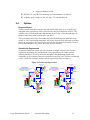
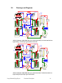

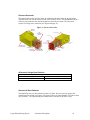
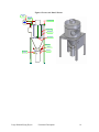


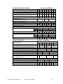
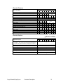

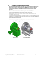
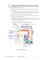
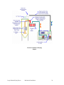
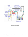
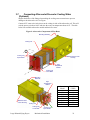
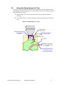
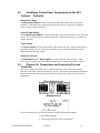
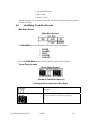
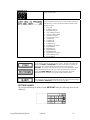
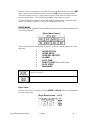

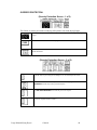
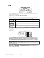

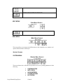
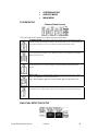

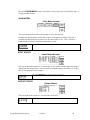
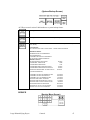
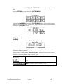
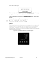


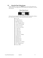
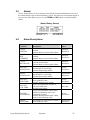
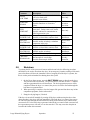
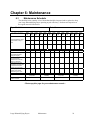


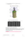
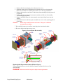
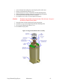
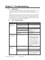
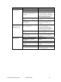


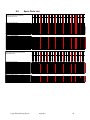
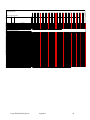
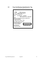


![Daylites II [Solo/Twin]](http://vs1.manualzilla.com/store/data/006631481_3-0358ea7773458df38d925e4ff46610d0-150x150.png)