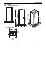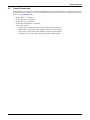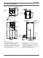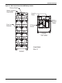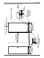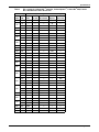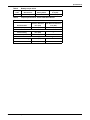
1
AC Power
For Business-Critical Continuity™
Liebert® SRT™ Battery Cabinet
Installation Manual–250 kW, 30 Seconds, Nominal, 240 VRLA Cells
CONTACTING EMERSON NETWORK POWER® FOR SUPPORT
To contact the Emerson Network Power Liebert® Services for information or repair service in the
United States, call 1-800-LIEBERT (1-800-543-2378). Liebert Services offers a complete range of
startup services, repair services, preventive maintenance plans and service contracts.
For repair or maintenance service outside the 48 contiguous United States, contact Liebert Services,
if available in your area.
For Liebert Services to assist you promptly, have the following information available:
Part Numbers:
Serial Numbers:
Rating:
Date Purchased:
Date Installed:
Location:
Battery Voltage:
Battery Reserve Time:
Product Warranty Registration
To register for warranty protection, visit the Service and Support section of our Web site at:
www.liebert.com
Click on Product Registration and fill out the form.
TABLE OF CONTENTS
CONTACTING EMERSON NETWORK POWER® FOR SUPPORT . . . . . . . . . . . . . . INSIDE FRONT COVER
IMPORTANT SAFETY INSTRUCTIONS . . . . . . . . . . . . . . . . . . . . . . . . . . . . . . . . . . . . . . . . . . . . . . . .1
SAVE THESE INSTRUCTIONS . . . . . . . . . . . . . . . . . . . . . . . . . . . . . . . . . . . . . . . . . . . . . . . . .1
1.0
MECHANICAL INSTALLATION . . . . . . . . . . . . . . . . . . . . . . . . . . . . . . . . . . . . . . . . . . . . . . . .4
1.1
Introduction . . . . . . . . . . . . . . . . . . . . . . . . . . . . . . . . . . . . . . . . . . . . . . . . . . . . . . . . . . . . . . . . 4
1.2
Preliminary Checks . . . . . . . . . . . . . . . . . . . . . . . . . . . . . . . . . . . . . . . . . . . . . . . . . . . . . . . . . . 4
1.3
Flooring Requirements. . . . . . . . . . . . . . . . . . . . . . . . . . . . . . . . . . . . . . . . . . . . . . . . . . . . . . . . 4
1.3.1
1.4
Floor Loading . . . . . . . . . . . . . . . . . . . . . . . . . . . . . . . . . . . . . . . . . . . . . . . . . . . . . . . . . . . . . . . . 4
Environmental Considerations . . . . . . . . . . . . . . . . . . . . . . . . . . . . . . . . . . . . . . . . . . . . . . . . . 4
1.4.1
1.4.2
1.4.3
Battery Room . . . . . . . . . . . . . . . . . . . . . . . . . . . . . . . . . . . . . . . . . . . . . . . . . . . . . . . . . . . . . . . . 4
Storage . . . . . . . . . . . . . . . . . . . . . . . . . . . . . . . . . . . . . . . . . . . . . . . . . . . . . . . . . . . . . . . . . . . . . 5
Clearances. . . . . . . . . . . . . . . . . . . . . . . . . . . . . . . . . . . . . . . . . . . . . . . . . . . . . . . . . . . . . . . . . . . 5
1.5
System Composition . . . . . . . . . . . . . . . . . . . . . . . . . . . . . . . . . . . . . . . . . . . . . . . . . . . . . . . . . . 5
1.6
Unloading and Unpacking . . . . . . . . . . . . . . . . . . . . . . . . . . . . . . . . . . . . . . . . . . . . . . . . . . . . . 5
1.6.1
1.6.2
1.6.3
1.6.4
1.7
5
6
7
8
Positioning the Liebert SRT . . . . . . . . . . . . . . . . . . . . . . . . . . . . . . . . . . . . . . . . . . . . . . . . . . 10
1.7.1
1.8
Inspection Before Removal From the Truck . . . . . . . . . . . . . . . . . . . . . . . . . . . . . . . . . . . . . . . .
Unloading . . . . . . . . . . . . . . . . . . . . . . . . . . . . . . . . . . . . . . . . . . . . . . . . . . . . . . . . . . . . . . . . . . .
Handling . . . . . . . . . . . . . . . . . . . . . . . . . . . . . . . . . . . . . . . . . . . . . . . . . . . . . . . . . . . . . . . . . . . .
Unpacking . . . . . . . . . . . . . . . . . . . . . . . . . . . . . . . . . . . . . . . . . . . . . . . . . . . . . . . . . . . . . . . . . . .
Moving the Liebert SRT . . . . . . . . . . . . . . . . . . . . . . . . . . . . . . . . . . . . . . . . . . . . . . . . . . . . . . . 10
Installation . . . . . . . . . . . . . . . . . . . . . . . . . . . . . . . . . . . . . . . . . . . . . . . . . . . . . . . . . . . . . . . . 11
1.8.1
1.8.2
1.8.3
1.8.4
Cabinet Floor Mounting . . . . . . . . . . . . . . . . . . . . . . . . . . . . . . . . . . . . . . . . . . . . . . . . . . . . . . .
Concrete, Masonry or Stone Floor Mounting . . . . . . . . . . . . . . . . . . . . . . . . . . . . . . . . . . . . . .
Wood Floor Mounting . . . . . . . . . . . . . . . . . . . . . . . . . . . . . . . . . . . . . . . . . . . . . . . . . . . . . . . . .
Raised Floor Mounting . . . . . . . . . . . . . . . . . . . . . . . . . . . . . . . . . . . . . . . . . . . . . . . . . . . . . . . .
12
13
16
17
2.0
BATTERY INSTALLATION . . . . . . . . . . . . . . . . . . . . . . . . . . . . . . . . . . . . . . . . . . . . . . . . . . 19
2.1
Safety . . . . . . . . . . . . . . . . . . . . . . . . . . . . . . . . . . . . . . . . . . . . . . . . . . . . . . . . . . . . . . . . . . . . 19
2.2
Layout . . . . . . . . . . . . . . . . . . . . . . . . . . . . . . . . . . . . . . . . . . . . . . . . . . . . . . . . . . . . . . . . . . . . 19
2.3
Cable Entry. . . . . . . . . . . . . . . . . . . . . . . . . . . . . . . . . . . . . . . . . . . . . . . . . . . . . . . . . . . . . . . . 20
2.4
Power Connection . . . . . . . . . . . . . . . . . . . . . . . . . . . . . . . . . . . . . . . . . . . . . . . . . . . . . . . . . . . 20
2.4.1
2.4.2
Stand-Alone System . . . . . . . . . . . . . . . . . . . . . . . . . . . . . . . . . . . . . . . . . . . . . . . . . . . . . . . . . 20
Grounding . . . . . . . . . . . . . . . . . . . . . . . . . . . . . . . . . . . . . . . . . . . . . . . . . . . . . . . . . . . . . . . . . . 20
2.5
Control Connections . . . . . . . . . . . . . . . . . . . . . . . . . . . . . . . . . . . . . . . . . . . . . . . . . . . . . . . . . 21
3.0
INSTALLATION DRAWINGS . . . . . . . . . . . . . . . . . . . . . . . . . . . . . . . . . . . . . . . . . . . . . . . . .22
4.0
SPECIFICATIONS . . . . . . . . . . . . . . . . . . . . . . . . . . . . . . . . . . . . . . . . . . . . . . . . . . . . . . . .28
i
FIGURES
Figure 1
Figure 2
Figure 3
Figure 4
Figure 5
Figure 6
Figure 7
Figure 8
Figure 9
Figure 10
Figure 11
Figure 12
Figure 13
Figure 14
Figure 15
Figure 16
Figure 17
Figure 18
Figure 19
Figure 20
Figure 21
Figure 22
Figure 23
Liebert SRT shipping package . . . . . . . . . . . . . . . . . . . . . . . . . . . . . . . . . . . . . . . . . . . . . . . . . . . . . . 6
Removing lag bolts . . . . . . . . . . . . . . . . . . . . . . . . . . . . . . . . . . . . . . . . . . . . . . . . . . . . . . . . . . . . . . . 8
Lifting the Liebert SRT cabinet . . . . . . . . . . . . . . . . . . . . . . . . . . . . . . . . . . . . . . . . . . . . . . . . . . . . . 8
Removing the metal support plates . . . . . . . . . . . . . . . . . . . . . . . . . . . . . . . . . . . . . . . . . . . . . . . . . . 9
Liebert SRT cabinet caster location . . . . . . . . . . . . . . . . . . . . . . . . . . . . . . . . . . . . . . . . . . . . . . . . . 10
Dimensions, general layout . . . . . . . . . . . . . . . . . . . . . . . . . . . . . . . . . . . . . . . . . . . . . . . . . . . . . . . 11
Floor mounting . . . . . . . . . . . . . . . . . . . . . . . . . . . . . . . . . . . . . . . . . . . . . . . . . . . . . . . . . . . . . . . . . 12
Floor mounting template layout. . . . . . . . . . . . . . . . . . . . . . . . . . . . . . . . . . . . . . . . . . . . . . . . . . . . 13
Checking hole depth . . . . . . . . . . . . . . . . . . . . . . . . . . . . . . . . . . . . . . . . . . . . . . . . . . . . . . . . . . . . . 14
Inserting anchors . . . . . . . . . . . . . . . . . . . . . . . . . . . . . . . . . . . . . . . . . . . . . . . . . . . . . . . . . . . . . . . 14
Expanding anchors . . . . . . . . . . . . . . . . . . . . . . . . . . . . . . . . . . . . . . . . . . . . . . . . . . . . . . . . . . . . . . 14
Securing mounting brackets to the cabinet . . . . . . . . . . . . . . . . . . . . . . . . . . . . . . . . . . . . . . . . . . . 15
Mounting rear bolts—rear side of cabinet . . . . . . . . . . . . . . . . . . . . . . . . . . . . . . . . . . . . . . . . . . . . 15
Mounting front bolts—front side of cabinet. . . . . . . . . . . . . . . . . . . . . . . . . . . . . . . . . . . . . . . . . . . 16
Raised floor mounting. . . . . . . . . . . . . . . . . . . . . . . . . . . . . . . . . . . . . . . . . . . . . . . . . . . . . . . . . . . . 18
Stand-alone battery cabinets, detached from UPS . . . . . . . . . . . . . . . . . . . . . . . . . . . . . . . . . . . . . 19
Other possible Liebert SRT configurations . . . . . . . . . . . . . . . . . . . . . . . . . . . . . . . . . . . . . . . . . . . 20
Outline drawing Liebert SRT Battery Cabinet . . . . . . . . . . . . . . . . . . . . . . . . . . . . . . . . . . . . . . . . 22
Main components Liebert SRT Battery Cabinet . . . . . . . . . . . . . . . . . . . . . . . . . . . . . . . . . . . . . . . 23
Liebert SRT cabinet mechanical installation . . . . . . . . . . . . . . . . . . . . . . . . . . . . . . . . . . . . . . . . . 24
Floor mounting template . . . . . . . . . . . . . . . . . . . . . . . . . . . . . . . . . . . . . . . . . . . . . . . . . . . . . . . . . 25
Raised floor mounting. . . . . . . . . . . . . . . . . . . . . . . . . . . . . . . . . . . . . . . . . . . . . . . . . . . . . . . . . . . . 26
Terminal details Liebert SRT Battery Cabinet. . . . . . . . . . . . . . . . . . . . . . . . . . . . . . . . . . . . . . . . 27
TABLES
Table 1
Table 2
Table 3
Table 4
Table 5
System information. . . . . . . . . . . . . . . . . . . . . . . . . . . . . . . . . . . . . . . . . . . . . . . . . . . . . . . . . . . . . . . 5
Liebert SRT Battery Cabinet specifications . . . . . . . . . . . . . . . . . . . . . . . . . . . . . . . . . . . . . . . . . . 28
DC currents for Liebert NXL™ modules, Liebert Npower™, Liebert Nx™ 480,
Liebert Nx™ 225-600 and Liebert Series 610™ . . . . . . . . . . . . . . . . . . . . . . . . . . . . . . . . . . . . . . . . 29
Torque specifications, unless otherwise labeled . . . . . . . . . . . . . . . . . . . . . . . . . . . . . . . . . . . . . . . 30
Battery torque values . . . . . . . . . . . . . . . . . . . . . . . . . . . . . . . . . . . . . . . . . . . . . . . . . . . . . . . . . . . . 30
ii
Important Safety Instructions
IMPORTANT SAFETY INSTRUCTIONS
SAVE THESE INSTRUCTIONS
This manual contains important instructions that should be followed during installation of your
Liebert SRT (Short Run Time) Battery Cabinet and accessories. Read this manual thoroughly, paying
special attention to the sections that apply to your installation, before working with the battery
system. Retain this manual for use by installing personnel.
The following warning applies to all battery cabinets supplied with UPS systems.
! WARNING
Risk of improper handling. Can cause equipment damage, injury and death.
Internal battery strapping must be verified before moving a battery cabinet (after initial
installation).
• Battery cabinets contain non-spillable batteries.
• Keep units upright.
• Do not stack.
• Do not tilt.
Failure to heed this warning could result in smoke, fire or electric hazard.
Call 1-800-LIEBERT before moving battery cabinets (after initial installation).
! WARNING
Risk of electrical shock. Can cause personal injury and death.
Special safety precautions are required for procedures involving handling, installation and
maintenance of the UPS system. Only properly trained and qualified personnel wearing
appropriate personal protective equipment should be involved in installing the Liebert SRT
battery system or preparing the system for installation.
Special care must be taken when working with the batteries associated with this equipment.
When connected together, the battery terminal voltage will exceed 400VDC and is potentially
lethal. Be constantly aware that the battery system contains high DC as well as AC voltages.
Check for voltage with AC and DC voltmeters before making contact.
Observe all DC safety precautions before working on or near the DC system.
Follow all battery safety precautions when installing, charging or servicing batteries. In
addition to the hazard of electric shock, gas produced by batteries can be explosive and
sulfuric acid can cause severe burns.
The following precautions must be observed when working on batteries:
•
•
•
•
•
•
Remove watches, rings and other metal objects.
Use tools with insulated handles.
Wear rubber gloves and boots.
Do not lay tools or metal parts on top of batteries.
Disconnect charging source prior to connecting or disconnecting battery terminals.
Determine whether the battery is grounded. If it is grounded, remove source of ground.
Contact with any part of a grounded battery can result in electrical shock. The likelihood of
such shock will be reduced if such grounds are removed during installation and maintenance.
If a battery leaks electrolyte, or is otherwise physically damaged, it must be replaced, stored
in a container resistant to sulfuric acid and disposed of in accordance with local regulations.
If electrolyte comes into contact with the skin, the affected area should be washed
immediately with water.
1
Liebert® SRT™ Battery Cabinet
Important Safety Instructions
! WARNING
Risk of electric shock, explosive reaction, hazardous chemicals and fire. Can cause equipment
damage, personal injury and death.
Lead-acid batteries contain hazardous materials. Batteries must be handled, transported and
recycled or discarded in accordance with federal, state and local regulations. Because lead is a
toxic substance, lead-acid batteries must be recycled rather than discarded.
Do not dispose of a battery in a fire. The battery may explode.
Do not open or mutilate the battery or batteries. Released electrolyte is harmful to the skin
and eyes. It is toxic.
! WARNING
Risk of electric shock. Can cause personal injury and death.
In case of fire involving electrical equipment, use only carbon dioxide fire extinguishers or
those approved for use in fighting electrical fires.
! WARNING
Risk of heavy unit falling over. Can cause equipment damage, injury and death.
Exercise extreme care when handling battery cabinets to avoid equipment damage or injury
to personnel. The battery cabinet weighs approximately 2376 lb. (1176kg).
Locate center of gravity symbols
and determine unit weight before handling each
cabinet. Test lift and balance the cabinets before transporting. Maintain minimum tilt from
vertical at all times.
Slots at the base of the cabinets are intended for forklift use. Base slots will support the unit
only if the forks are completely beneath the unit.
! WARNING
Risk of electric shock. Can cause equipment damage, personal injury and death.
The area around the battery system must be kept free of puddles of water, excess moisture
and debris.
Observe all precautions in the UPS user manual before as well as during all installation and
maintenance procedures. Observe all battery safety precautions before working on or near the
battery.
This equipment contains several circuits that are energized with high voltage. Only test
equipment designed for troubleshooting should be used. This is particularly true for
oscilloscopes. Always check with an AC and DC voltmeter to ensure safety before making
contact or using tools. Even when the power is turned Off, dangerously high potential electric
charges may exist at the capacitor banks and at the batteries.
All power and control wiring must be installed by a properly trained and qualified electrician.
All power and control wiring must comply with the NEC and applicable local codes.
When performing maintenance with any part of the equipment under power, service
personnel and test equipment must be standing on rubber mats. The service personnel must
wear insulating shoes for isolation from direct contact with the floor (earth ground).
One person should never work alone, even if all power is disconnected from the equipment. A
second person should be standing by to assist and to summon help in case of an accident.
NOTE
Materials sold hereunder cannot be used in the patient vicinity (e.g., use where UL, cUL or IEC
60601-1 is required). Medical applications such as invasive procedures and electrical life
support equipment are subject to additional terms and conditions.
Liebert® SRT™ Battery Cabinet
2
Important Safety Instructions
NOTICE
This unit complies with the limits for a Class A digital device, pursuant to Part 15 Subpart J
of the FCC rules. These limits provide reasonable protection against harmful interference in a
commercial environment. This unit generates, uses and radiates radio frequency energy and,
if not installed and used in accordance with this instruction manual, may cause harmful
interference to radio communications. Operation of this unit in a residential area may cause
harmful interference that the user must correct at his own expense.
3
Liebert® SRT™ Battery Cabinet
Mechanical Installation
1.0
MECHANICAL INSTALLATION
1.1
Introduction
This following section describes the requirements that must be taken into account when planning the
positioning and cabling of the Liebert SRT battery equipment.
This chapter is a guide to general procedures and practices that should be observed by the installing
engineer. The particular conditions of each site will determine the applicability of such procedures.
NOTICE
Do not apply electrical power to the UPS equipment before the arrival of the commissioning
engineer.
1.2
Preliminary Checks
Before installing the battery equipment, please carry out the following preliminary checks:
• Visually examine the equipment for transit damage, both internally and externally. Report any
damage to the shipper immediately.
• Verify that the correct equipment is being installed. The equipment supplied has an identification
tag inside the main door.
• Verify that the battery room satisfies the environmental conditions stipulated in the equipment
specification, paying particular attention to the ambient temperature and air exchange system.
1.3
1.3.1
Flooring Requirements
Floor Loading
The Liebert SRT should be mounted on a finished surface, such as concrete, block, brick or wood. The
floor must be strong enough to support the equipment load and suitable for installation of an anchoring kit with vertical floor loading properly calculated (assume 2,000 PSI or 140 kg/cm2 contact load at
caster wheels; this includes safety factors).
• When installing on a concrete, masonry or stone floor, use the factory-supplied masonry fasteners
(anchors). The fastener manufacturer’s allowable shear load (parallel to floor) for these fasteners
is 2,030 lb. (9 kN) when mounted in normal-weight concrete (2,000 to 3,000 PSI; 140-210 kg/cm2)
of at least 3 in. (7.6cm) thickness.
• If installing on a floor consisting of a material other than normal-weight concrete as described
above, the mounting should be capable of sustaining a shear load (parallel to floor) of at least
1,500 lb. (6.7 kN) for each of the four mounting points.
• If installing on a raised floor that is less than 2 in. (5cm) thick or constructed of a material not
appropriate for the masonry fasteners provided or lag screw engagement, mount using through
bolts with nuts and large diameter washers as shown in Figure 155.
Full details for mounting the cabinet are found in 1.8.1 - Cabinet Floor Mounting.
NOTE
The above loads (both the fastener manufacturer load and the minimum mounting load)
include the required safety factors.
1.4
Environmental Considerations
1.4.1
Battery Room
Batteries should be mounted in an environment where the temperature is consistent and even over
the whole battery. Temperature is a major factor in determining the battery life and capacity. Typical
battery manufacturer performance data are quoted for an operating temperature between 68 and
77°F (20 and 25°C). Operating above this range will reduce the battery life while operation below this
range will reduce the battery capacity.
Liebert® SRT™ Battery Cabinet
4
Mechanical Installation
Battery Temperature
In a normal installation, the battery temperature should be kept between 59 and 77°F (15°C and
25°C).
NOTE
Keep batteries away from main heat sources, main air inlets, etc.
1.4.2
Storage
Should the equipment not be installed immediately, it must be stored in a room for protection against
excessive humidity and heat sources (see Table 2).
NOTICE
Risk of deep discharge. Can cause permanent damage to batteries.
An unused battery must be recharged periodically as recommended by the battery
manufacturer.
1.4.3
Clearances
The Liebert SRT has no ventilation grilles at either side or at the rear of the battery system
equipment. Clearance around the front of the equipment should be sufficient to enable free passage of
personnel with the doors fully opened. It is important to leave a distance of 24" (610mm) between the
top of the cabinet and the ceiling of the room in which it is installed to permit adequate circulation of
air coming out of the unit and for service access.
1.5
System Composition
A battery system can consist of a number of equipment cabinets, depending on the individual system
design requirements, e.g., Battery Cabinet, Junction Cabinet. Refer to 3.0 - Installation Drawings
for the positioning of the cabinets described below.
1.6
Unloading and Unpacking
1.6.1
Inspection Before Removal From the Truck
While the Liebert SRT shipping package is still on the truck:
• Inspect the equipment and shipping container(s) for any signs of damage or mishandling. Check
also if the shock and tilt gauges (installed for shipping purposes) indicate excessive shock and/or
tilting. If any damage is noted, file a damage claim with the shipping agency within 24 hours and
contact your local sales representative or Liebert at 1-800-LIEBERT to notify them of the damage
claim and the condition of the equipment.
• Compare the contents of the shipment with the bill of lading. Report any missing items to the carrier, your local Emerson representative and Emerson at 1-800-LIEBERT immediately. Please
have the bill of lading available.:
! CAUTION
Do not attempt to install the system if damage is apparent.
Table 1
System information
Date Purchased
Date Installed
Location
System Model Number
System Serial Number
Interconnected UPS Manufacturer
Interconnected UPS Model
5
Liebert® SRT™ Battery Cabinet
Mechanical Installation
1.6.2
Unloading
Figure 1
Liebert SRT shipping package
Shipping
Support
Bands
(on either
side)
76"
(1933mm)
Metal
Support
Plates
(one on
either side)
Side View
Front View
Conduit
Plates
Battery
Access
Plates
PC Board
Access
FRONT
TOP VIEW
The Liebert SRT as shipped (see Figure 1) can weigh up to 2376 lb. (1176kg). It must be handled
with care. It must be kept upright—pay special attention to the arrows, which indicate the upright
position.
Liebert® SRT™ Battery Cabinet
6
Mechanical Installation
1.6.3
Handling
The Liebert SRT shipping package is designed to be handled using a forklift. Forklift operators must
avoid rough handling when picking up, moving and lowering it.
! WARNING
Risk of improper transport. Can cause equipment damage, injury and death.
The Liebert SRT is heavy. It weighs 2538 lb. (1256kg) as shipped; 2376 lb. (1176kg) uncrated.
Move the unit only with a device that is rated for transporting that weight.
Exhibit care when handling Liebert SRT cabinet to avoid causing the unit to fall. Test lift and
balance the cabinet before transporting it. Maintain minimum tilt from vertical at all times.
Do not exceed 15 degrees of tilt.
! CAUTION
Risk of sharp edges, splinters and exposed fasteners. Can cause injury.
Sheet metal components and framework may have sharp edges. Only properly trained and
qualified personnel wearing appropriate safety headgear, gloves, shoes and glasses should
attempt to move the unit, lift it, remove packaging from or prepare the unit for installation.
NOTICE
Risk of improper handling. Can cause equipment damage.
The Liebert SRT has sensitive electronics and mechanical components that may be damaged
by rough handling.
7
Liebert® SRT™ Battery Cabinet
Mechanical Installation
1.6.4
Unpacking
To reduce the possibility of shipping damage, Liebert SRT cabinets are secured to the pallet by two
mounting brackets and two banding straps. These same two mounting brackets are used to mount the
cabinet to the floor.
Packing elements should be removed in this order to ease unpacking:
1. Cut and remove the banding straps (see Figure 1).
! WARNING
Risk of sharp edges under tension. Can cause injury or death.
Use care when removing banding straps and metal mounting brackets. The banding straps
are under tension and may snap violently, causing injury or death. Always wear proper eye,
hand and foot protection when unpacking or installing the system.
2. Remove hex head bolts holding mounting brackets to pallet as shown in Figure 2.
3. Remove lag bolts holding metal mounting brackets to pallet.
4. Remove mounting brackets from Liebert SRT.
Figure 2
Removing lag bolts
Lag bolts
securing
Liebert SRT to
shipping pallet
Metal mounting
bracket bolted to
shipping pallet
5. Use a forklift to remove the cabinet from the shipping pallet.
To lift the Liebert SRT, the forks should be inserted between the caster wheel assemblies (see
Figure 3). Forks must be extended to the full depth of the cabinet—at least 6 ft. (2m) fork
length—to properly support the equipment (see Figure 3). This likely requires fork extenders.
The Liebert SRT can weigh up to 2376 lb. (1176kg) and must be handled with care.
Figure 3
Lifting the Liebert SRT cabinet
Forks must be
extended the
full depth of the
cabinet
Liebert® SRT™ Battery Cabinet
8
Mechanical Installation
6. Unbolt and remove the two metal support plates (one on either side of the pallet).
Figure 4
Removing the metal support plates
Metal
support
plate
Caster
(for moving
short
distances)
Leveling
foot (one
on each
corner)
NOTE
Retain the four bolts (1/2" diameter x 1-3/4" long; 12.7mm diameter x 44.5mm long) attaching
the metal support plates to the cabinet. These will be used to attach brackets to the cabinet for
surface mounting.
7. Examine the Liebert SRT internally and externally for transit damage. Report any damage to the
shipper, your local Emerson representative and Emerson immediately.
! CAUTION
Do not attempt to install the system if there is any damage.
8. Check visually for loose connections and unsecured components in the cabinet.
9. You will find the installation manual, operation manual and options manual (if any) enclosed in
the pocket inside the cabinet door.
10. You will find the serial number and model number plate mounted on the cabinet door pocket or on
the upper right corner of the face of the cabinet frame inside the door. Record the model number
and serial number in Table 1 - System information.
9
Liebert® SRT™ Battery Cabinet
Mechanical Installation
1.7
Positioning the Liebert SRT
1.7.1
Moving the Liebert SRT
When moving the unit a short distance, the Liebert SRT may be rolled on its built-in casters (see
Figure 5) to its location.
! CAUTION
Risk of improper handling. Can cause equipment and building damage, injury or death.
efore moving the Liebert SRT across a floor, determine whether the surface will support the
unit’s weight—2538 lb. (1256kg) as shipped; 2376 lb. (1176kg) uncrated.
Figure 5
Liebert SRT cabinet caster location
Casters on each corner
(for moving unit short
distances only)
When moving the unit a longer distance or over rough flooring, move the Liebert SRT with a forklift
or similar equipment to facilitate the relocation and to reduce vibration of the unit.
! CAUTION
Ensure that the handling equipment is rated for the weight of the
Liebert SRT—2538 lb. (1256kg) as shipped; 2376 lb. (1176kg) uncrated.
Liebert® SRT™ Battery Cabinet
10
Mechanical Installation
1.8
Installation
The Liebert SRT system design and safety characteristics allow for a relatively simple and quick
installation. The system is designed to be rolled or lifted into place and bolted to the floor using
Liebert's mounting kit, included with the system. The mounting kit in most cases does not require
any special floor preparations (see 1.6 - Unloading and Unpacking).
NOTICE
Risk of improper installation. Can cause equipment damage and void warranty.
The Initial System Startup must be performed ONLY under the supervision of an
Emerson-certified service technician to ensure proper system operation. Failure to abide by
instructions provided herein may void your warranty.
Contact your local Emerson sales representative or Emerson at 1-800-LIEBERT to arrange
for system startup.
NOTICE
Risk of improper installation. Can cause equipment damage.
The Liebert SRT system must be installed in accordance with the instructions and drawings
in this manual.
Never attempt to install or power up any unit suspected of damage during shipment.
Figure 6
Dimensions, general layout
Conduit
Plates
Top
Battery
Access
Plates
PC Board
Access
FRONT
TOP VIEW
71.1"
(1801mm)
Bottom
25"
(636mm)
Front
11
32.5"
(828mm)
Right Side
12-100120-09
Rev. 1
Liebert® SRT™ Battery Cabinet
Mechanical Installation
1.8.1
Cabinet Floor Mounting
NOTE
Before beginning, ensure that the floor where the Liebert SRT will be mounted meets the floor
loading specifications in 1.3 - Flooring Requirements.
• For placement on concrete, masonry or stone floors, see Mounting Kit for Concrete, Masonry
or Stone Floors on page 13.
• For placement on wood floors, see 1.8.3 - Wood Floor Mounting.
• For placement on raised floors, see 1.8.4 - Raised Floor Mounting.
Figure 7
Floor mounting
Floor Mounting
Bracket
Liebert® SRT™ Battery Cabinet
12
Mechanical Installation
1.8.2
Concrete, Masonry or Stone Floor Mounting
Mounting Kit for Concrete, Masonry or Stone Floors
Emerson has included a complete anchoring kit with each Liebert SRT for surface mounting. The kit
is intended to securely fasten the Liebert SRT to its intended location for operational safety and seismic requirements.
This kit includes:
•
•
•
•
•
•
•
•
Two (2) cabinet mounting brackets (from shipping pallet)
Four (4) concrete expansion anchors
Two (2) drop-in hex head anchor bolts
Two (2) washers for anchor bolts
One (1) masonry drill bit
One (1) floor mounting template (Figure 21)
Two (2) drop-in hex flange anchor bolts
One (1) setter rod or drive pin (specifically designed for measuring hole depth and for expanding
the anchors)
• Four (4) hex bolts from shipping package, each 1/2" diameter and 3/4" long (12.7mm diameter x
20mm long)
Mounting Tools
These tools are needed for the mounting the Liebert SRT on the floor:
•
•
•
•
•
•
•
•
Concrete drill with 1/2" (12.7mm) minimum chuck size
Masonry drill bit (included in mounting kit)
Masonry drill bit—used for pilot hole—for example, 1/8" (3.2mm) diameter
Setter rod (included in mounting kit)
Hammer or mallet, 16 oz. (0.5kg) or larger
Shop vacuum cleaner (to remove dust from hole when drilling)
3/4" (19mm) combination wrench
18mm combination wrench
Concrete, Masonry or Stone Floor Mounting Instructions
To mount the Liebert SRT cabinet on the floor:
1. Prepare a clean, level, finished surface, free of obstructions, for installation of the mounting kit.
2. Tape the floor mounting template mounting template (Figure 21) to the installation location.
3. Using a bit smaller than the one provided in the mounting kit, drill a pilot hole at each of the four
places marked with an “X” on the template.
4. Remove template and continue with larger drill bit provided.
Figure 8
Floor mounting template layout
16"
(406mm)
X
X
Drill 4 holes, each
2" (51mm) deep,
with 5/8" masonry bit
X
29-1/2"
(749mm)
X
Front of Liebert SRT
13
Liebert® SRT™ Battery Cabinet
Mechanical Installation
5. Drill 2" (51mm) deep holes in prepared surface using the drill bit included in the kit per bolt
pattern described in Figure 21 - Floor mounting template. The setter rod should be used as a
depth gauge to ensure proper depth. The setter rod is marked with two circles indicating the
maximum and minimum hole depth allowed (see Figure 9).
If a hole is drilled too deep, refill the hole with debris to the achieve proper depth.
Figure 9
Checking hole depth
Setter Rod (provided)
Depth Marks
Concrete Floor
2.05"
(52mm)
6. Insert four (4) drop-in concrete expansion anchors into drilled holes.
Figure 10 Inserting anchors
Insert anchor flush with floor .
Use hammer if required.
7. Tap anchors into drilled holes using hammer or mallet. When top of anchor is flush with
mounting surface, use setter rod to expand and secure.
Figure 11 Expanding anchors
Strike with
hammer
to set plug
Liebert® SRT™ Battery Cabinet
14
Mechanical Installation
8. Match mounting brackets with the holes on the bottom of the cabinet (see Figure 12). Make sure
that the bracket holes align with the mounting spots on the underside of the cabinet and secure
the brackets with the four 1/2" diameter x 3/4" long (12.7mm diameter x 20mm long) hex bolts
retained from the shipping package. Tighten the bolts with a torque of 40 foot-pounds (54 N-m).
Figure 12 Securing mounting brackets to the cabinet
Bolt securing bracket
to cabinet
9. Insert the two (2) hex flange bolts in the rear anchors, where the back of the cabinet will be.
Complete tightening of the rear bolts should result in 1/2" (12.7mm) gap between bolt flange and
floor (see Figure 13 and Figure 20). The rear bolts must be tightened to 20 foot-pounds (27 N-m)
of torque. Bolt height or length may need to be adjusted if mounting surface is uneven or if
mounting bracket does not slide beneath bolt flange.
10. Position and align cabinet and bracket slots with the newly inserted bolts at rear and position
cabinet such that bolts fit in bracket slots (see Figure 13).
Figure 13 Mounting rear bolts—rear side of cabinet
1/2"
(12.7mm)
floor to
flange
15
Liebert® SRT™ Battery Cabinet
Mechanical Installation
11. Insert and begin tightening two (2) hex head bolts with one washer each through bracket
mounted at front of cabinet into anchor inserts in mounting surface (see Figure 14).
Figure 14 Mounting front bolts—front side of cabinet
12. Firmly tighten the front bolts to drop-in anchors as shown in Figure 21. The front bolts must be
tightened to 40 foot-pounds (54 N-m) of torque.
1.8.3
Wood Floor Mounting
Determine which of these cases applies to your installation:
• For wood flooring over concrete, follow the instructions in Mounting Kit for Concrete,
Masonry or Stone Floors on page 13.
• For wood flooring on joists, follow the instructions in this section.
Wood Floor Mounting Parts
• Two (2) cabinet mounting brackets (previously secured Liebert SRT cabinet to shipping pallet)
• Four (4) (1/2" diameter x 2-1/2" long) [or 12.7mm diameter x 63.5mm] lag screws (not included in
mounting kit) are recommended
• One floor mounting template, see Figure 21
• Four (4) 1/2" diameter x 3/4" long (12.7mm diameter x 20mm long) hex bolts (from shipping package—see 1.6.4 - Unpacking)
Wood Floor Mounting Tools
The following tools are needed for the cabinet wood floor mounting:
•
•
•
•
•
•
Electric drill
1/4" (7mm) drill bit
Drill bit—used for pilot hole—for example, 1/8" (3.2mm) diameter
Shop vacuum cleaner (to remove dust from hole when drilling)
3/4" (19mm) combination wrench
18mm combination wrench
Liebert® SRT™ Battery Cabinet
16
Mechanical Installation
Wood Floor Mounting Instructions
Installation in wood floor on joists does not require drop-in anchors.
1. Prepare a clean, level surface, free of obstructions, for installation of the mounting kit.
2. Tape the floor mounting template (Figure 21) to the installation location.
3. Drill pilot holes, remove the template and use a 1/4" (7mm) drill bit to drill holes 2.5" (64mm)
deep.
NOTICE
4.
5.
6.
7.
8.
1.8.4
Risk of improper installation. Can cause equipment damage.
Ensure that holes are centered in the joist. Holes that are not centered may not anchor the
unit securely.
Match mounting brackets with holes under base of cabinet (see Figure 12). Make sure that the
bracket holes align with the mounting spots on the underside of the cabinet and secure brackets
with the four hex bolts retained from the shipping package. Each bolt is 1/2" diameter x 3/4" long
(12.7mm diameter x 20mm long). Tighten the bolts with a torque wrench at 40 foot-pounds
(54 N-m).
Insert two lag screws through bracket mounted at rear of cabinet leaving head with 1/2" (12.7mm)
gap above floor (see Figure 13).
Position and align cabinet and bracket slots with the newly drilled holes at rear and position
cabinet such that bolts fit in bracket slots (see Figure 13).
Insert two (2) lag screws through bracket mounted at front of cabinet (see Figure 14).
Firmly tighten the front lag screws to a torque 40 foot-pounds (54 N-m).
Raised Floor Mounting
Raised Floor Mounting Kit
Emerson has included a complete anchoring kit with each Liebert SRT for surface mounting. The kit is
intended to securely fasten the Liebert SRT to its location for operational safety and seismic requirements.
The anchoring kit includes:
• One floor mounting template, Figure 21
• 2 cabinet mounting brackets
• 4 drop-in hex flange bolts, each 1/2" diameter, 3" long (12.7mm, 76.mm)
• 4 washers (1/2" hole and 2" outer diameter) for hex flange bolts
• 4 lock washers for hex flange bolts
• 4 nuts for hex flange bolts, each 1/2" (12.7mm)
• 4 hex bolts, each 1/2" diameter, 3/4" long (12.7mm diameter, 20mm long) retained from shipping
package (see 1.6.4 - Unpacking)
Raised Floor Mounting Tools
The following tools are needed for the cabinet raised floor mounting:
• Electric drill with 1/2" (12.7mm) minimum chuck size
• 5/8" (16mm) drill bit
• Drill bit—used for pilot hole—for example, 1/8" (3.2mm) diameter
• 3/4" (19mm) combination wrench
• 18mm combination wrench
17
Liebert® SRT™ Battery Cabinet
Mechanical Installation
Raised Floor Mounting Instructions
To mount the Liebert SRT cabinet on the floor:
1. Prepare a clean, level finished surface, free of obstructions, for installation of mounting kit.
2. Tape the floor mounting template (see Figure 21) to installation location, pre-drill a pilot hole,
then remove paper and continue with 5/8" (16mm) drill bit.
3. Match mounting brackets with holes under base of cabinet (see Figure 12). Make sure that the
bracket holes align with the mounting spots on the underside of the cabinet and secure brackets
with the four 1/2" diameter x 3/4" long (12.7mm diameter x 20mm long) hex bolts retained from
the shipping package. The bolts must be tightened to 40 foot-pounds (54 N-m) of torque.
4. Position and align cabinet and bracket slots with the newly drilled holes (see Figure 13).
5. Insert four drop-in hex flange bolts through bracket mounted at front and rear of cabinet (see
Figure 14).
Figure 15 Raised floor mounting
Large diameter washer
2"
(50mm) dia .
Lockwasher
1/2" (12.7mm)
dia. steel bolt
Raised
floor
6. Attach a large diameter washer, a lock washer and a nut to each hex flange bolts as described in
Figure 15 and Figure 22.
7. Firmly tighten down all hex flange bolts with nuts. The bolts must be tightened to 40 foot-pounds
(54 N-m) of torque.
Liebert® SRT™ Battery Cabinet
18
Battery Installation
2.0
BATTERY INSTALLATION
2.1
Safety
Special care should be taken when working with the batteries associated with the Liebert SRT
Battery System equipment. When all the cells are connected together, the battery terminal voltage
will exceed 400V and is potentially lethal. A primary safety consideration is to install the battery
equipment in an isolated area, accessible only to properly trained and qualified maintenance
personnel.
! WARNING
Risk of electric shock. Can cause equipment damage, personal injury and death.
Hazardous battery voltage present behind covers. No user-serviceable parts are located
behind covers that require a tool for removal. Only properly trained and qualified service
personnel are authorized to remove such covers or perform installation or maintenance.
The following general battery safety precautions and warnings must be observed at all times:
• A battery can present risk of electric shock or burn from high short circuit currents.
• When connected in a string, the voltage will exceed 400VDC. This voltage is potentially
lethal. Always observe high-voltage precautions.
• Eye protection must be worn to prevent injury from accidental electrical arcs.
• Remove rings, watches, necklaces, bracelets and all other metal objects.
• Use only tools with insulated handles.
• Wear appropriate personal protective equipment when handling batteries.
• If a battery leaks electrolyte or is otherwise physically damaged, it should be placed in a
container resistant to wire and disposed of in accordance with local regulations.
• If electrolyte comes into contact with the skin, the affected area should be washed immediately with plenty of clean water.
• Batteries must always be disposed of according to local environmental laws.
• When replacing batteries, use the same number and type that were originally fitted.
• Disconnect charging source prior to connecting or disconnecting battery terminals.
• Determine if the battery is grounded. If it is grounded, remove source of ground. Contact
with any part of a grounded battery can result in electrical shock.
• Battery support tray must be used whenever a battery tray is being pulled out.
2.2
Layout
The battery cabinets must be installed stand-alone, where the cabinet is not bolted to the UPS. See
Figures 16 and 18 for possible configurations.
Figure 16 Stand-alone battery cabinets, detached from UPS
Liebert
SRT
Battery
Cabinet
Liebert
UPS
19
Liebert® SRT™ Battery Cabinet
Battery Installation
Figure 17 Other possible Liebert SRT configurations
Liebert
UPS
StandAlone
Junction
Cabinet
Module
Battery
Disconnect
Liebert
SRT
Battery
Cabinet
Liebert
UPS
StandAlone
Junction
Cabinet
Additional
Liebert
SRT
Battery
Cabinets
Additional
Liebert
SRT
Battery
Cabinets
Maximum of eight
battery cabinets.
The junction
cabinet provides
sufficient conduit
landing space and
may be required.
Contact your
Emerson
representative for
details.
2.3
Additional
Liebert
SRT
Battery
Cabinets
Cable Entry
Cables may enter the battery cabinet from the top only. Cable entry is made possible by installing
conduit to the removable plate fitted at the top of the cabinet. See 3.0 - Installation Drawings.
2.4
Power Connection
Power connections between the Liebert SRT and the UPS and safety precautions are detailed in the
UPS installation or user manuals. See the Liebert documents listed below. Each is available at the
Liebert Web site, www.liebert.com
•
•
•
•
•
2.4.1
Liebert NXL™—SL-25430
Liebert Npower™—SL-24532
Liebert Nx™ 480—SL-25217
Liebert Nx 225-600 kVA—SL-25356
Liebert Series 610™:
• 65-225 kVA—SL-25120 single module; SL-25125 multi-module
• 300-450 kVA—SL-25130 single module; SL-25135 multi-module
• 500-750 kVA—SL-25140 single module; SL-25145 multi-module
• 1000 kVA—SL-251550 single module; SL-25160 multi-module
Stand-Alone System
For cabinets that are ordered as stand-alone, customer must supply all the interconnecting cables and
hardware. See Table 3 for maximum discharge currents and size power cables accordingly.
2.4.2
Grounding
Customer must supply the cables and hardware. See terminal detail drawings for the location of the
ground busbar.
Liebert® SRT™ Battery Cabinet
20
Battery Installation
2.5
Control Connections
Control connections between the Liebert SRT Battery Cabinet and the UPS are detailed in the UPS
installation or user manuals. See the Liebert documents listed below. Each is available at the Liebert
Web site, www.liebert.com
•
•
•
•
•
Liebert NXL™—SL-25430
Liebert Npower™—SL-24532
Liebert Nx™ 480—SL-25217
Liebert Nx 225-600 kVA—SL-25356
Liebert Series 610™:
• 65-225 kVA—SL-25120 single module; SL-25125 multi-module
• 300-450 kVA—SL-25130 single module; SL-25135 multi-module
• 500-750 kVA—SL-25140 single module; SL-25145 multi-module
• 1000 kVA—SL-251550 single module; SL-25160 multi-module
21
Liebert® SRT™ Battery Cabinet
Installation Drawings
3.0
INSTALLATION DRAWINGS
Figure 18 Outline drawing Liebert SRT Battery Cabinet
3.1"
(78.7mm)
Battery
Access
Plates
Conduit Entry
6.5" x 6"
Top Only;
2 Places
32.6"
(829mm)
18.8" (478mm)
Caster Centers
11.4" (290mm)
Caster Centers
22.6" (574mm)
Caster Centers
25" (635mm)
Top View
Maximum
Door Swing
120 Degrees
Bottom View
Circuit
Breaker
DC Busbars
Circuit
Breaker
DC Busbars
Control and
Power Wire
Side Access
Approximate Area
4.6" x 2.2"
(Both Sides)
Pure Lead
Battery
71"
(1804mm)
Center
of
Gravity
Center
of
Gravity
35.5"
(902mm)
Leveling
Feet
(See Note 11)
Support Tray
and Support
Bracket
(See Note 10)
3.2" (80mm)
17.2" (438mm)
12.4" (315mm)
50.4" (1279mm)
Front View
Side View
NOTES
1. All dimensions are in Inches (mm).
9. The shipping weight is 2538 lb. (1256kg); the uncrated weight is
2. 24" (610mm) minimum clearance above the unit is required for
air exhaust and 36" (914mm) front access is required for service.
2376lb. (1176kg).
3. Keep the cabinet within 15 degrees of vertical while handling.
10. Before sliding batteries out on the battery tray, position the support
4. Top cable entry is available through access plates.
tray and attach it to the cabinet. Then secure two support brackets to
5. The bottom ofthe unit is structurally adequate for forklift handling.
the support tray and to the cabinet. Refer to the appropriate user
6. Control wiring and power wiring must be run in separate conduits.
manual for further description and details.
7. Unless otherwise noted, all cables must be suitable for at least 75°C
11. The leveling feet are not designed to carry the full weight of the cabinet.
and must be copper conductors only.
Finger-tighten the levelers against the floor, thentighten with a wrench
8. All wiring must be in accordance ith national and local electrical codes.
less than two turns for a friction fit against the floor.
Liebert® SRT™ Battery Cabinet
22
Installation Drawings
Figure 19 Main components Liebert SRT Battery Cabinet
Battery Breaker
Battery Interface
Board (BIB)
Conduit
Plates
Battery
Access
Plates
Pure Lead
Batteries
PC Board
Access
FRONT
TOP VIEW
PLB11000
Rev. 0
FRONT
23
Liebert® SRT™ Battery Cabinet
Liebert® SRT™ Battery Cabinet
24
Half-Size View of Floor Anchor
Front Mount
25"
(635mm)
Front View
36" (914mm)
Minimum
Front Clearance
32-5”
(825.5mm)
Right-Side View
Half-Size View
of Floor Anchor
Rear Mount
.5"
(12.7mm)
Do Not
Tighten
Weight: 2376 lb. (1176kg)
24" (610mm) Overhead Clearance
Installation Drawings
Figure 20 Liebert SRT cabinet mechanical installation
min.
max.
NOTE: If hole is drilled too deep, backfill to correct
to proper depth.
4X O5/8" (16mm) Mason Drill x 2.00 (51mm)
2.25 (57mm)
29-1/2"
(749mm)
16"
(406mm)
Installation Drawings
Figure 21 Floor mounting template
25
Liebert® SRT™ Battery Cabinet
Installation Drawings
Figure 22 Raised floor mounting
F
29-½” (75mm)
F
16” (406mm)
F
F
TOP VIEW
Large diameter washer
2"
(50mm) dia.
Lockwasher
1/2" (12.7mm)
dia. steel bolt
Raised
floor
NOTE: Combination of floor material of given thickness, plus
properties of large diameter washer and fastener, should result in
lateral load capability to withstand shear due to load F=2376 lb (1176kg),
parallel to floor.
For thicker floors that might require a bolt length longer than
can fit inside mounting channel, insert bolt from below with nut above.
Liebert® SRT™ Battery Cabinet
26
Installation Drawings
Figure 23 Terminal details Liebert SRT Battery Cabinet
10" (254.0mm)
.63"
(15.9mm)
Front
1.75"
(44.5mm)
DC (+) Busbar
.63"
(15.9mm)
DC (-) Busbar
1.25"
(31.8mm)
3.0"
(76.2mm)
Top View
DC (+) Busbar
Ø.437"
(11.10mm)
TYP.
DC (+) Busbar
DC (-) Busbar
1.75"
(44.5mm)
.63"
(15.9mm)
Ø.437"
(11.1mm)
Typ.
1.5"
(38.1mm)
.88"
(22.2mm)
71"
(1804mm)
65.8"
(1671mm)
7" (177.8mm)
DC (-) Busbar
Ground Lug
(Hole is .365 diameter
for a 1/4-inch hole lug)
PLB13000
Rev. 0
Right Side
Without Batteries
27
Liebert® SRT™ Battery Cabinet
Specifications
4.0
SPECIFICATIONS
Table 2
Liebert SRT Battery Cabinet specifications
Values
Top-Terminal Cabinet
Battery Cabinet Parameters
Battery Type
VRLA (Valve Regulated Lead Acid) Enersys XE60
Battery Breaker
250A (with 6x setting)
480V
Nominal Battery Bus, VDC
540V
Battery Float Voltage, VDC
400V (for VRLA)
Minimum EOD Voltage, VDC
Battery Discharging Maximum Current (EOD),
ADC
720A (One Cabinet)
Physical Parameters and Standards
Width, in. (mm) 1
25.0 (635)
2
32.6 (829)
Depth, in. (mm)
Height, in. (mm)
71 (1804)
Weight, lb (kg) approx.
2376 (1176)
Standard Color
Black (ZP-7021)
Front Door Opening (for serviceability)
More than 180°
IP 20 (with and without front door open)
Degree of Protection for UPS Enclosure
Minimum Clearance, Top
24" (610mm)
Minimum Clearance, Back
0"
Minimum Clearance, Sides
0"
Cable Entrance
Top
UL 1778; CSA 22.2 107.3
FCC Part 15, Class A; ISTA Procedure 1H; WEEE;
IBC 2012/CBC 2010
Standards & Conformities
Environmental
Storage Temperature Range, °F (°C)
-13°F to 158°F (-25°C to 70°C)
74°F to 80°F (23-27°C) for optimal battery life
Operating Temperature Range, °F (°C)
32°F to 104°F (0 to 40°C)
74°F to 80°F (23-27°C) for optimal battery life
up to 95% Non-Condensing
(Operating and Non-Operating)
Relative Humidity
Maximum Altitude Above MSL, ft (m)
4920 (1500) (as per IEC 62040/3) 1% Maximum kW derate / 100m rise between 1500-3000m
1. Width dimensions are with side panels attached. Subtract 1.4" (35mm) for dimensions without side panels.
2. Depth dimensions include the front door and rear panel.
Liebert® SRT™ Battery Cabinet
28
Specifications
DC currents for Liebert NXL™ modules, Liebert Npower™, Liebert Nx™ 480, Liebert
Nx™ 225-600 and Liebert Series 610™
Table 3
UPS Rating
Max Battery Discharge Current at EOD (Amps)
kVA
kW
Liebert
NXL
Liebert
Nx 480
Liebert
Nx 225-600
Liebert
Npower
Liebert
Series 610
30
24
—
—
—
66
—
32
—
—
—
88
—
40
36
—
103
—
—
—
50
40
—
—
—
109
—
60
54
—
155
—
—
—
65
52
—
—
—
141
—
64
—
—
—
174
—
72
—
206
—
—
—
80
—
—
—
218
218
90
—
258
—
—
—
120
108
—
309
—
—
—
125
100
—
—
—
—
271
130
104
—
—
—
283
—
150
120
—
—
—
—
326
160
144
—
412
—
—
—
200
180
—
515
—
—
—
180
—
—
—
—
488
225
—
—
586
—
—
225
615
—
—
—
—
250
—
—
653
—
—
240
—
—
—
—
651
270
730
—
—
—
—
300
—
—
786
—
—
320
—
—
—
—
868
360
980
—
—
—
—
400
—
—
1048
—
—
400
—
—
—
—
1079
450
—
—
—
—
1214
500
1241
—
1310
—
—
600
—
—
1572
—
—
80
100
225
250
300
400
500
600
625
750
500
—
—
—
—
1349
625
1648
—
—
—
—
600
—
—
—
—
1619
675
1850
—
—
—
1822
800
800
2061
—
—
—
—
1000
900
—
—
—
—
2440
1100
1100
2860
—
—
—
—
29
Liebert® SRT™ Battery Cabinet
Specifications
Table 4
Battery torque values
Battery
Code
Manufacturer
Battery Model
Torque Value
in-lb (Nm)
PG
Enersys
XE60
60 (6.7)
Table 5
Torque specifications, unless otherwise labeled
Bus bar
Bolt Shaft Size
Grade 2 Standard
lb-in (Nm)
Electrical Connections
with Belleville Washers
lb-in (Nm)
3/8 (M10)
192 (22)
95 (11)
Current Rating
lb-in (Nm)
—
250 Amps
90 (10)
—
Circuit Breakers
Circuit Breakers with Compression Lugs (For Control Wiring)
AWG Wire Size or Range
lb-in (Nm)
—
#22 - #14
3.5 to 5.3 (0.4 to 0.6)
—
Liebert® SRT™ Battery Cabinet
30
Ensuring The High Availability
Of Mission-Critical Data And Applications.
Emerson Network Power, a business of Emerson (NYSE:EMR),
is the global leader in enabling Business-Critical Continuity™
from grid to chip for telecommunication networks, data centers,
health care and industrial facilities. Emerson Network Power
provides innovative solutions and expertise in areas including
AC and DC power and precision cooling systems, embedded
computing and power, integrated racks and enclosures,
power switching and controls, infrastructure management,
and connectivity. All solutions are supported globally by local
Emerson Network Power service technicians. Liebert AC power,
precision cooling and monitoring products and services
from Emerson Network Power deliver Efficiency Without
Compromise™ by helping customers optimize their data center
infrastructure to reduce costs and deliver high availability.
Technical Support / Service
Web Site
www.liebert.com
Monitoring
[email protected]
800-222-5877
Outside North America: +00800 1155 4499
Single-Phase UPS & Server Cabinets
[email protected]
800-222-5877
Outside North America: +00800 1155 4499
Three-Phase UPS & Power Systems
800-543-2378
Outside North America: 614-841-6598
Environmental Systems
800-543-2778
Outside the United States: 614-888-0246
Locations
United States
1050 Dearborn Drive
P.O. Box 29186
Columbus, OH 43229
Europe
Via Leonardo Da Vinci 8
Zona Industriale Tognana
35028 Piove Di Sacco (PD) Italy
+39 049 9719 111
Fax: +39 049 5841 257
Asia
29/F, The Orient Square Building
F. Ortigas Jr. Road, Ortigas Center
Pasig City 1605
Philippines
+63 2 687 6615
Fax: +63 2 730 9572
While every precaution has been taken to ensure the accuracy
and completeness of this literature, Liebert Corporation assumes no
responsibility and disclaims all liability for damages resulting from use of
this information or for any errors or omissions.
© 2010 Liebert Corporation
All rights reserved throughout the world. Specifications subject to change
without notice.
® Liebert is a registered trademark of Liebert Corporation.
All names referred to are trademarks
or registered trademarks of their respective owners.
SL-25431_REV1_04-13
Emerson Network Power.
The global leader in enabling Business-Critical Continuity™
AC Power
Connectivity
Embedded Computing
Embedded Power
DC Power
Infrastructure Management & Monitoring
Outside Plant
Power Switching & Controls
Precision Cooling
EmersonNetworkPower.com
Racks & Integrated Cabinets
Services
Surge Protection
Emerson, Business-Critical Continuity, Emerson Network Power and the Emerson Network Power logo are trademarks of Emerson Electric Co. or one of its affiliated companies.
©2010 Emerson Electric Co.