1
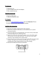
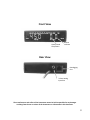
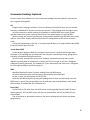
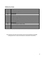
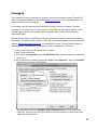
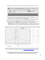
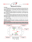
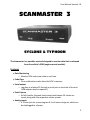
User Manual Version 1.0 SCANMASTER 3 SYCLONE & TYPHOON The Scanmaster is a portable scantool designed to monitor data that is retrieved from the vehicle’s ECM (engine control module). Features Data Monitoring o Monitor ECM and sensor data in real time. Code Clear o Clear malfunction codes from the ECM’s memory. Serial output o Log data to a laptop PC through a serial port on the back of the unit. (USB adapter may be required.) Peak Capture o At full throttle, the peak knock retard and leanest O2 values are saved, along with the respective vehicle speeds. Analog inputs o A 3.5mm jack for connecting two 0-5 volt external signals, which can be datalogged to a laptop. 1 Kit Contents 1. Scanmaster unit 2. External logging cable with serial adapter 3. Misc. wiring connectors Available accessories 1. Serial to USB adapter 2. Optional analog input cable For Support On the web, www.turbotweak.com/forum, go to the Scanmaster 3 forum. You can go there to find out about any recent updates. Installing the Scanmaster 1. Disconnect the battery negative cable under the hood. 2. Mount the Scanmaster inside the car on the dashboard, or any other convenient location. 3. Connect the black wire to a good ground. You can use a skinny male spade terminal to plug into pin A, which is ground. 4. Connect the red wire to a fused ignition power source. One of the empty IGN terminals in the fuse box works well. You can install a male spade connector, which will push into an IGN terminal. 5. Connect the white wire to the serial data signal at the ALDL connector under the dash. The signal is pin M, bottom row, far right. You can use the included skinny male spade connector to push into the plug. 6. Reconnect the battery and test the Scanmaster. ALDL Connector pin M 2 Front View Open/Closed Loop Status Record Indicator Rear View Datalogging Port 3.5mm Analog Input Port The manufacturers and sellers of the Scanmaster cannot be held responsible for any damages resulting from the use or misuse of the Scanmaster or information in this document. 3 Operating Instructions Power Up On initial key-on, the Scanmaster version number will be displayed. If no data is received the Scanmaster will turn itself back off. Once it has synchronized with the ECM, the display will change to “450 0.0“ (O2 millivolts and knock retard). Default Mode After the Scanmaster has synchronized with the ECM, it will enter Default mode. On the left side of the display you will see O2 millivolt readings from the engine’s oxygen sensor. On the right side it will display degrees of knock retard, which correlates with how bad the car is knocking (detonating). Pressing the Mode button (to the left of the display digits) selects other data from various engine sensors. Each time you press Mode, it will scroll through data until you get back to O2 and knock retard again. You can also press Recall to return to O2 and knock. Configuration Mode The following display parameters are configurable: 1. Default O2 display – stock O2 reading or wideband reading 2. Boost & MAP display – stock 2-bar MAP sensor or 3-bar MAP sensor 3. Optional analog input display – wideband type (AEM, LC-1, etc). Use this only if you have a wideband connected directly to the Scanmaster (not wired to the ECM). To enter Configuration Mode, with the Scanmaster powered up, hold the Mode button for 10 seconds. Press the Mode button to scroll through menu of items. Use the Recall button to change parameter. Press Mode again twice to save the parameter. To leave Configuration mode, hold the Mode button for 5 seconds. You will see the Scanmaster reset. Configuration menu items: 1. MAP – 0 = stock 2 bar, 1 = 3-bar 2. Ad1 – choose type of wideband (if one is connected to the Scanmaster analog input). 1 = PLX or AEM Gauge 30-4100, 2 = LC1, 3 = AEM Inline & AEM 30-5130 3. Ad2 – not currently configured 4. O2 – 0 = show stock O2’s on main screen, 1 = show wideband O2 on main screen Record Mode While in Default mode, if the TPS (Throttle Position Sensor) voltage exceeds roughly 3 volts, the Scanmaster will monitor O2 and knock retard. It will keep in its memory the highest knock retard reading and lowest O2 reading along with the MPH that they occurred. The 6th decimal point (to the right of the knock retard digits) will be lit during recording. The stored readings can be recalled anytime before the engine is turned off. 4 Recall Mode While in Default mode, pressing the Recall button (on the right of the knock retard display) changes the Scanmaster to Recall mode. In this mode, any previously recorded O2 millivolt and knock retard readings will be displayed. Pressing the Mode button and Recall at the same time displays the MPH values associated with the stored O2 and retard values. Turning the engine off will erase all stored data. Clearing Malfunction Codes To clear any malfunction codes stored in the ECM’s memory: 1. Turn key on and make sure the Scanmaster has connected with the ECM. 2. Press the Mode button until the “MAL” parameter is displayed. 3. Press and hold the Recall button until the Scanmaster resets. 4. Any malfunction codes should be cleared. Information Displayed on Scanmaster Display O2 KR MAP bSt AFr bat Int bL MPH CLt AtS r tPS IAC CC MAL inJ SP bdc Description Oxygen Sensor Knock Retard Manifold pressure Boost Air/Fuel Ratio Battery Volts Integrator Block Learn (BLM) Miles per hour Coolant Temp Air Temp Sensor Engine RPM Throttle Position Sensor Idle Air Control Cross Counts Malfunction Code Injector Pulsewidth Spark Advance Boost duty cycle Open or Closed Loop Status Note Range O2 in millivolts, optional wideband AFR .000-.999 Timing retard in degrees due to knock 0.0-25.6 Manifold absolute pressure in kPa 0-315 Actual Boost in PSI 0.0-30.0 ECM Commanded AFR or Wideband AFR 0.0-20.0 Voltage from ignition 0.0-25.6 Short term fuel trim 90-150 Long term fuel trim 90-150 Vehicle speed 0-255 Current coolant temperature -40° to 300° Current manifold air temperature -40° to 300° RPM 0-6400 Voltage reading from TPS 0.0-5.0 Commanded position of IAC motor 0-255 Activity of oxygen sensor 0-255 Stored malfunction codes Injector pulsewidth in milliseconds Spark advance in degrees Wastegate solenoid duty cycle in percent 0.0-99.9% Decimal point in knock retard reading will blink for open loop, or remain solid for closed loop. 5 Scanmaster Readings Explained Here are some short definitions for the Scanmaster readings. Not every detail is covered, but this is a good starting point. O2 Oxygen sensor reading in millivolts. Gives an indication of air/fuel mixture, but not terribly accurate. A wideband O2 system is much more accurate. Take readings with the engine warm. At full throttle we’re usually looking for anywhere in the 900-1000 area. Leaner (lower) typically makes more power, but may cause knock. The typical target is in the mid 900’s. When cruising, the numbers should jump up and down anywhere from 000-900. Some chips utilize a “lean cruise” feature which will drop the O2 reading down to 100 or less at certain times. During idle, depending on the chip, it may jump up and down, or it might stabilize above 800 if the chip utilizes open loop idle. Knock Retard (KR) Knock retard in degrees. When the computer senses knock, it retards the timing to help eliminate it. This reading tells you how much the computer retarded the timing, giving you an indication of how bad the knock event was. At full throttle, we would like to see zero. However, sometimes you may see a couple degrees here and there on a downshift, or when you first hit the gas. If you see 2-3 degrees momentarily and it goes away, it’s probably ok. If you continuously see more than 2-3 degrees, let off the gas and figure out what’s going on. MAP Manifold Absolute Pressure. Pressure reading from the MAP sensor. At full throttle and around 14-15psi boost, this would be around 200 kPa. At idle, in park, you will typically see 30-35 kPa. Note that just because you may see good readings here, it does not necessarily mean the MAP sensor is good. They can go slightly out of calibration and cause problems, such as bad BLM readings, or cruddy idle, tip-in stumbles, etc. Boost (bSt) Actual boost in PSI, taken from the MAP sensor. Anything under 0psi will read 0 (it won’t display vacuum). A 2-bar MAP sensor will max out around 15psi, and a 3-bar MAP will max around 30psi. Due to variances in atmospheric pressure, the boost reading may not match your boost gauge exactly. 6 Ait/Fuel Ratio (AFr) Air/Fuel Ratio. For a stock chip, this will display what A/F the ECM is trying to command. It’s not always what you actually end up with. For some newer chips, they are set up to display the A/F from a wideband O2 connected to the ECM. So this reading may show the wideband A/F, instead of the ECM commanded A/F. Typically at idle, you might see an A/F of 13.0 to 15.0 depending on the chip, etc. Cruising is usually in the 14.0-15.5 range, and full throttle around 11.0-12.0. All of this can depend on how the chip is tuned, and many other factors. Battery (bat) System voltage as read by the computer from the ignition switch. It would be ideal to have this above 13.5 volts most of the time, but some cars do drift down closer to 13.0 volts at times. Low voltage can reduce the output of your fuel pump. INT Integrator (Short term fuel trim). Default number is 128 (which is 0%). When higher than 128, the computer is adding fuel, and less than 128, the computer is subtracting fuel. This number changes rapidly when operating in closed loop as the computer is constantly adding or subtracting fuel based on input from the O2 sensor. The computer is trying to keep the air/fuel mixture as close to 14.7:1 as possible for emissions purposes. This number will be moving around a lot between 118 and 138 or so. Don’t pay too much attention to it in most cases. BLM is more important. When in open loop (during cold start, or idle on some chips), this will stay at 128. BLM (bL) Block Learn Memory (Long term fuel trim). Works very similar to INT, but this is the computer’s way of remembering the fuel trim over a longer period. There are 2 or more different BLM memory locations (called “cells”) that are accessed based on different load conditions. The Scanmaster only displays the value of the currently used BLM cell. Like the Integrator, the default value is 128 (0%). We would like to see the BLM stay in the 118-138 range. It’s not the end of the world if it goes outside this range, but it could indicate there is a problem somewhere. MPH Vehicle speed in mile per hour. Coolant Temp (CLt) Coolant temperature in degrees F. Most guys change to a colder 160° stat to keep the engine cooler which helps eliminate knock. This may allow you to run more boost. Airtemp (AtS) Manifold air temperature in degrees F. The sensor is located in the intake plenum. 7 RPM (r) Engine speed in revolutions per minute. Idle speed depends on what is programmed in the chip, but usually somewhere in the 700-850rpm area. TPS Throttle position sensor voltage. Take reading with key on, engine off. Full throttle position should typically be over 4.00 volts. Idle position (foot off gas) should be around .50-.80 normally. This is not really adjustable on the SyTy’s, so if it’s way off, it might indicate a bad TPS sensor. IAC Idle Air Control. Position of the idle air motor in "counts" or "steps" from 00 (00 is closed). At idle warmed up in park, normal is around 20-40. It will jump up higher when in drive. It will also move around when pressing on the gas (called the throttle follower function). When you turn the engine off, the IAC resets itself and will return to a higher number for startup. When you turn the key on the next time, it will be at that higher number until you start the car. It will then creep down as the engine warms up. Cross Counts (CC) Cross Counts. Counter that keeps track of how many times the O2 reading crosses midpoint (.450-.500mv). This counter starts at 0 and climbs until it hits 255, then starts at 0 again. This can give you an idea of the condition of the O2 sensor. In closed loop, you would typically see this number climb around 10-20 numbers per frame (each time the Scanmaster refreshes). If the number is climbing slowly, then you may need a new O2 sensor. If you have a chip that uses open loop idle, the cross counts will not change much at idle. MAL Malfunction code display. Injector Pulsewidth (inJ) Injector pulsewidth. This is displaying the actual amount of time that the injectors are pulsing to squirt fuel. It is displayed in milliseconds (ms). No real “correct” reading here. It’s just for monitoring purposes. Spark Advance (SP) Spark Advance. Displays ignition spark advance. This is what the ECM is commanding, and may not be actual advance if the distributor is out of adjustment. 8 Malfunction Codes Code Number 13 14 15 21 22 23 24 25 31 32 33 34 35 42 43 44 45 51 Description O2 sensor Coolant temp sensor high Coolant temp sensor low TPS sensor high TPS sensor low Air temp sensor low (MAT) Vehicle speed sensor Air temp sensor high (MAT) Wastegate solenoid, overboost EGR MAP sensor signal high MAP sensor signal low Idle speed error EST circuit failure (ignition module to ECM) ESC circuit failure (knock sensor) Oxygen sensor lean Oxygen sensor rich Prom error (chip or socket) The manufacturers and sellers of the Scanmaster cannot be held responsible for any damages resulting from the use or misuse of the Scanmaster or information in this document. 9 Datalogging The Scanmaster can be connected to a laptop to record data using the software TunerPro V5, which can be downloaded from the website www.tunerpro.net in the download section. It is free but donations are encouraged. A serial data cable included with the Scanmaster connects the unit to a laptop. The cable connector is for a serial port, so if your laptop only has USB, you will need an adapter. Note that the logging cable is not a standard phone modular cable. Contact TurboTweak for replacement parts. After installing TunerPro, a definition file will be necessary to properly communicate with the Scanmaster. This definition file, called an “ADX” file, can be downloaded from the TurboTweak website, www.turbotweak.com/forum in the download section. You may need to register to download (free). Download the file and save it into the same folder as TunerPro. 1. Connect the cable from the Scanmaster to laptop. 2. Start TunerPro software. 3. Go to menu item Acquisition, then Load Definition File… Browse to where the ADX file is and open it. 4. Set up acquisition by selecting menu item Tools, then Preferences… Select the Data Acq. tab and set up the area circled below. You may have to press the Configure Plug-In Component button to set up the right COM port. There may be a little trial and error with the COM port to find the one that works. Hit OK when done. 10 5. With the Scanmaster powered up, you can press the Acquire Data button to connect. 6. Then select how you want to display the data. Go to menu item Acquisition, and at the bottom of the menu are different ways to display the data. 7. To record data or stop recording, you can go to Acquisition, then Start/Stop Data Scan. 8. When you are done recording, it will ask you to name the file before saving. 9. To replay records, go to Acquisition, then Load Log File… and select the log file. You will need to pick a way to display the data using the selections at the bottom of the Acquisition menu. For example, selecting Show Monitors… will show you something like the example below. You can “right-click” on the screen to select what data you want to display. There are many features of TunerPro that cannot be covered here, so look though its help files and don’t hesitate to ask questions. You can go to www.turbotweak.com/forum for support. The manufacturers and sellers of the Scanmaster cannot be held responsible for any damages resulting from the use or misuse of the Scanmaster or information in this document. 11