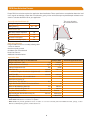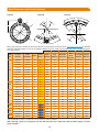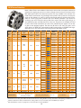
1
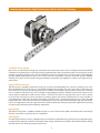
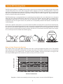
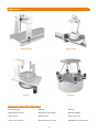
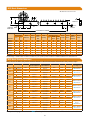
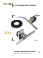
PRECISION MOTION CONTROL
THE ROLLER PINION SYSTEM
Application and Selection Guide
ii
Index
Introducing Innovative, High-Performance, Motion Control Technology ......................................................................................................... 1
The Nexen RPS Advantage .......................................................................................................................................................................... 2
How the RPS Technology Works .............................................................................................................................................................. 3
Applications ................................................................................................................................................................................................... 4
RPS Linear Drive
Selection Process .................................................................................................................................................................................. 5
Models, Sizes and Specifications ..................................................................................................................................................... 7
Dimensions and Product Numbers ..................................................................................................................................................... 8
RPG Rotary Drive
Selection Process ................................................................................................................................................................................. 9
Standard Gears, Specifications, and Product Numbers ............................................................................................................. 11
Gear Dimensions and Product Numbers .......................................................................................................................................... 12
Pinions and Adaptors
Options & Specifications ...................................................................................................................................................................... 13
Dimensions and Product Numbers ..................................................................................................................................................... 15
Preloaders
Dimensions and Product Numbers ..................................................................................................................................................... 17
Definitions ...................................................................................................................................................................................................... 19
iii
Introducing Innovative, High-Performance, Motion Control Technology
The Roller Pinion System
Nexen offers an advanced technology that revolutionizes linear and rotary motion control. The Roller Pinion System (RPS)
is based on an innovative pinion consisting of bearing-supported rollers and a unique tooth profile. This unique drive system
provides very high positional accuracy, near-zero backlash, virtually no cumulative error, low-velocity ripple, unlimited length,
very high speeds, high rigidity, low noise, low (in some cases no) maintenance, corrosion resistance, long life, and 99%
efficiency. This opens up new machine design possibilities and provides the capability to achieve much higher levels of
performance.
High Positional Accuracy
The RPS system is capable of positional accuracy up to ± 30 μm and repeatability of ± 5 μm at its meshing line or circle.
Near-zero backlash of less than 3.2 μm is achieved by multiple rollers engaging the rack or gear teeth in opposition at all
times. Due to the very high manufacturing precision of the RPS system and the special section joining tool, cumulative
error is virtually nonexistent over any rack run length or segmented gear diameter. The RPS system also provides very low
velocity ripple for applications where uniform motion is essential. This allows for high precision linear or rotary systems
of any size that can rely on the servo encoder for positioning without the need for separate linear or rotary encoders in
many applications. Unlike many other drive technologies, the RPS system’s positional accuracy does not start to degrade
progressively after a short time, but maintains its performance over its life until the pinion bearings reach the ends of their
lives. In most applications the rack or gear life will far exceed the pinion life, allowing several pinion replacements restoring
full rated system performance before needing replacement.
High Speeds
The Roller Pinion System is capable of speeds as high as 11 m/sec. Even at these speeds, the extremely low friction design
does not create heat or significant wear on components.
High Rigidity
As machine performance increases, rigidity becomes more important. Unlike ballscrews with their long unsupported lengths,
or traditional rack and pinion with their small teeth that flex, fatigue, and break out, the RPS’s robust tooth and pinion design
eliminate these issues allowing maximum performance.
1
The Nexen RPS Advantage
Long Life, Low Maintenance, and High Efficiency
The RPS system uses needle bearings to support the rollers that engage the teeth. This eliminates the sliding friction found
in many other motion control systems and gives it an efficiency greater than 99%. This high efficiency means little is lost to
friction, heat, and wear, providing a long life of 60,000,000 pinion revolutions (up to 36 million meters of travel). The rack
or gear tooth life rating varies by product model, environmental conditions, and lubrication intervals. Typically the pinion
can be replaced numerous times before the rack or gear will need replacement. In linear applications the rack can be run
lubrication free if maximum speed is under 0.5 m/s and Premium or Endurance models of rack utilized with a small reduction
in rack life. This is a great advantage in:
• Clean Environments such as food processing, pharmaceutical, coating, or clean room applications requiring low particle
emissions.
• Dirty Environments such as wood processing, mining, or grinding where particles in the environment would be attracted
to and mix with the rack lubrication, making an abrasive paste that can accelerate the wear rate.
• Inaccessible Applications where it is very difficult and/or hazardous to access machinery for periodic maintenance.
Modular System
Nexen offers the rack in standard meter and half-meter lengths that can also be cut as required.
Standard product lengths make the RPS available for immediate shipment, eliminating the lead
times required by other products, and make it easy for OEMs to keep a limited amount of product
on hand while covering a wide range of applications. The rotary RPG system is available as solid
rings up to 1.7 m diameter and segmented rings or arcs beyond this with no limits on the diameter
possible. Rack and arc segments are joined with a special alignment tool that uses two tooth
valleys on each section to minimize the introduction of positional inaccuracy. With these modular
components, rack runs of any length can be easily created.
Alignment
Tool
Low Noise
The pinion rollers approach the tooth face in a tangent path and then move smoothly along the face of each tooth. This
reduces noise levels often associated with other motion control systems like tooth slap or ball return noise.
Product Options
The RPS rack is available in five models, Premium, Endurance, Standard, Universal, and Stainless Steel Universal. Each
offers performance characteristics and price to suit a wide range of applications. Some pinion and rack models are available
with corrosion resistant surface treatments and/or made from 17-4 stainless steel for difficult applications. Pinions are
available in shaft mount with a keyless mechanical compression coupling or ISO 9409 flange mount versions for optimal
machine design flexibility. The RPS ISO 9409 flange mount pinions make reducer selection and mounting easier, allows
the use of Nexen pinion preloaders, and gives maximum system performance.
Overcomes the Limitations of Other Motion Control Technologies
The RPS’s unique design eliminates many of the problems found in these other commonly used drive systems:
• Ball Screws Limited by: Length, maximum speed, cumulative error, rigidity, and thermal expansion. Also suffers from
noise, vibration, particle emissions, low efficiency and life, high maintenance, and can require liquid cooling in demanding
applications.
• Traditional Rack & Pinion or Gear Systems Limited by: Backlash, low accuracy, speed, and life. Positional accuracy
continuously degrades due to tooth wear. Continuous lubrication is required to slow the wear rate and creates a mess
that can be a problem in many applications. They also suffer from noise, vibration, particle emissions, velocity ripple, and
tooth fatigue. Backlash is a problem unless expensive dual-pinion or split-pinion systems are employed, but they drive
up the cost greatly and accelerate wear.
• Belt Drives Limited by: Low load capacity, accuracy, rigidity, length, and life. Also suffers from backlash, belt stretch,
particle emissions, and chemical attack.
• Chain Drives Limited by: Backlash limits positional accuracy, meshing is noisy and can cause vibration that can effect
control systems, and tend to have high wear and maintenance due to stretch and lubrication requirements.
• Linear Motors & Direct Drive Rotary Stages Limited by: Low load capacity and efficiency, high cost, strong magnetic
fields, and liquid cooling in demanding applications. Typically is very expensive especially with long runs or large diameters.
2
How the RPS Technology Works
The RPS system achieves its incredible performance by using a pinion consisting of bearing-supported rollers that engage
a unique tooth profile. Two or more rollers engage the teeth in opposition at all times, eliminating backlash. There is no
tooth slap as with traditional rack and pinion or gearing, instead the RPS rollers approach the tooth face in a tangent path
and then roll smoothly down the tooth face. This provides a smooth, quiet, low-friction, fatigue-free, high-efficiency rotaryto-linear or rotary-to-rotary motion conversion.
The RPS tooth design is conceptually different from traditional gearing. It behaves like a cam and follower versus the typical
sliding spur gear used with traditional rack and pinion or gear sets. As illustrated in the figures below, a cycloidal curve is
created when a point drawn on a circle at point P rolls on a flat plane to point P’ without slipping. When multiple points
are placed on the circle at regular intervals, the cycloidal curves are repeatedly created on the flat plane, and develop into
a tooth-like profile.
A roller then is placed at each point P to act as pinion teeth and modifies the tooth profile to create the rack teeth. Normally,
this concept will not provide zero backlash, but a technical innovation was developed to modify the tooth geometry allowing
two rollers to remain loaded in opposition at all times, eliminating the backlash as the rollers engage the teeth. The rollers
meet the tooth with a tangent path and smoothly roll down the tooth face. This eliminates tooth slap, sliding friction, fatigue,
noise, and low precision associated with traditional gearing.
Rollers in
Opposition
P
P'
Rotary to Linear Transmission Precision
The variations shown in the graph below represent minor errors occurring throughout the pinion’s travel. The individual
waves indicate each roller/tooth meshing error, and larger wave patterns show pinion rotational error. As the horizontal
limits illustrate, there is no cumulative error. This pattern continues regardless of distance, even when crossing joints due
to the way the RPS alignment tool transfers the system accuracy from section to section.
Positional Error (µm)
60
40
20
16
0
-20
-20
-40
-60
0
100
200
300
400
500
600
700
800
Distance Traveled (mm)
Regardless of the distance traveled, positional accuracy remains constant with the RPS System.
3
Applications
Gantry Router
Robotic Arm
Indexer
Rotopod
Additional RPS and RPG Applications:
• Medical Imaging
• Welding
• Gantries
• Measurement Systems
• Wood Cutting & Shaping
• Material Handling
• Clean Rooms
• Machine Tools
• Food Processing
• Vacuum Environments
• Plasma and Laser Cutting
• Multihead on a Common Axis
4
RPS Linear Drive Selection Process
Proper RPS model size selection requires the application data listed below. These specifications are needed to determine:
load mass, load acceleration, force due to acceleration, gravity, friction, and total force of the load. See page 6 for sample
calculations to determine the correct RPS size for your application.
Typical Friction Coefficients (µ)
0.005
Ball Bearing Guide Rail
0.02
Polymer Bushing Guide
0.1
Bronze Bushing Guide
0.2
Velocity
Fa
F1
F2
etc.
Shock Factor3 (K)
Shockless Smooth Operation
1.0
Normal Operation
1.2
Operation with Impact
1.5
Operation with High Impact
2.5
v
t
Required Data for RPS Selection
Weight to be Driven (W)
Time
Example Data
1
kg
150.0 kg
Maximum Velocity (v)
m/s
0.5 m/s
Acceleration Time (t)
or Known Acceleration (preferred)2
seconds
m/s2
Other Forces (F1), (F2) etc.
Travel Distance
Fg
Customer Application Data
1.2
N
0N
0.01
Frictional Coefficient (µ) See table above
Angle from Horizontal (q°)
Ff
0 Degrees
from
Horizontal
0.5 s
Shock Factor 3 (K) See table above
4
In
gu clu
id din w
e g
co a
m ll d
po riv
ne e
nt &
s
Profile Guide Rail
This curve will select
the smallest RPS size
°
60°
m
5.4 m
Cycles Per Day 5
1000
Weight to be driven should include all drive components and structures being moved. If the axis is driven by more than one RPS system
and has a movable or asymmetric mass, the load distribution’s effect on the load each pinion must carry must be taken into account.
For example: an X&Y axis gantry where the Y axis shifts on the X axis causing the mass the RPS systems on each side of the X axis to
see to vary or other similar situation.
2
Acceleration based on time is linear and may not be representative of actual curve. A known acceleration from the servo drive provider
is preferred.
3
Shock Factor indicates the smoothness of operation.
4
Other Forces may include cutting forces, springs, counter balances, fluid dampening systems, wind resistance, etc.
5
Cycles Per Day assumes going the full Travel Distance and returning to home each time.
1
General Application Information
Application Description
Environmental Conditions
Required Positional Accuracy
Other Application Data
5
Calculating RPS Requirements
Based on the information on the preceding page, perform the calculations listed below. If the acceleration or deceleration
times are different, or there are other changes in velocity over the run, calculate the acceleration forces for each interval
and use the highest one for RPS selection purposes. Actual peak acceleration from a servomotor and reducer supplier
is preferred to acceleration curves based on velocity/time since they may underestimate the true acceleration forces. The
following example assumes a single pinion driving an axis. Axis driven by multiple pinions should take load distribution
issues into account.
Calculations
Example
Load Mass: w = m
m = 150.0 kg
Load Acceleration: a = v ÷ t or known acceleration
a = 0.5 m/s ÷ 0.5 s = 1.0 m/s2
Force Due to Acceleration: Fa = m x a
Fa= 150.0 kg x 1.0 m/s2 = 150.0 N
Force Due to Gravity: Fg = m x g x sin(degrees from horizontal)
Fg= 150.0 kg x 9.81 m/s2 x sin(60o)= 1274.4 N
Force Due to Friction: Ff = mass x µ x gravity x cos(degrees from horizontal)
Ff= 150.0 kg x 0.01 x 9.81 m/s2 x cos(60o) = 7.4 N
Total Force: Ft = Fa + Fg + Ff + F1 + F2 + ,, ect.
Ft= 150.0 N + 1274.4 N + 7.4 N = 1431.8 N
Total Force with Shock Factor: Fk = Ft x K
Fk= 1431.8 N x 1.2 = 1718.2 N
Now proceed to the RPS Rack Model Comparison Table at the top of page 7 and determine which rack model best
fits your needs. Then compare the Total Force with a Shock Factor of 1718.2 N (as calculated above) to the rack
model desired in the RPS Rack Model vs. Size vs. Thrust Capacity Table (also on page 7) to determine the correct
RPS size.
If the Premium rack model is selected due to it’s corrosion resistance and ability to run without lubrication at speeds
0.5 m/s or less, it requires an RPS size 25 or greater. If the Universal rack model is selected, then an RPS size 32
or greater is required.
Now review the RPS Rack Size Common Specifications Table at the bottom of page seven for other limiting factors
like speed, life, temperature range, or other attributes that may effect RPS suitability. The following additional
calculations are optional and assume that RPS25 Premium model rack has been selected.
Calculations
Example
Required Pinion Torque: tP = FT x Meshing Pitch Circle Diameter ÷ 2000
tP = 1718.2 N x 79.6 mm ÷ 2000 = 68.4 Nm
Pinion RPM: R P = 60,000 x v ÷ Linear Distance Per Pinion Revolution
R P = 60,000 x 0.5 m/s ÷ 250.0 mm = 120.0 RPM
Motor Power Required 1: P = TP x R P ÷ 9549
P = 68.4 Nm x 120.0 RPM ÷ 9549 = 0.9 kW
Daily Travel Distance: TP = Travel Distance x Cycles Per Day x 2
TD = 5.4 m x 1000 CPD x 2 = 10,800 m
Estimated Rack Life 2: LR = Tooth Contact Life ÷ Cycles Per Day ÷ 2
LR = 30,000,000 ÷ 1000 ÷ 2 = 15,000 Days
Estimated Pinion Life 2: LP = Pinion Revolution Life x Distance Per Rev ÷ TD
LP = 60,000,000 x 0.25 m ÷ 10,800 m = 1389 Days
Motor Power Required is an estimate that does not include reducer inefficiencies.
Estimated Life is based on the Life Rating criteria on page 19 and going the full Travel Distance each time. The combined rack and
pinion system will have the life of the lower of the two. Individual components can generally be replaced prior to exceeding their
Estimated Life, or when their performance diminishes and gaining the remaining life of the other components. If travel is variable,
calculate each zone separately.
1
2
Note: A
lways consult the RPS Rack or Gear User Manual before beginning your machine design or installing RPS
product to ensure obtaining the highest possible performance and easiest installation. User Manuals are
available on www.nexengroup.com on the product pages for any of the product numbers in the left hand
column under resources.
6
Selecting RPS Rack Models, Sizes, and Specifications
RPS Rack Model Comparison Table
Attributes
Positional Accuracy 1
Meshing Error Per Pitch 1
Repeatability 1
Backlash 1
RPS Model
Premium
Standard
Endurance
30
10
5
50
15
10
80
30
20
100%
200%
100%
200%
100%
200%
Hard Chrome
None
High
None
Millions
30
30
<30m/min
db
o
C
Yes
No
± µm
± µm
± µm
< µm
Dynamic Load Capacity Per RPS Size
Static Load Capacity Per RPS Size
Corrosion Resistant Surface Treatment 1
Corrosion Resistance Rating 1
Tooth Contact Life 1
Lubrication Free Operation 1
Noise Level 1
Temperature Range1
Universal
(Stainless)
50
30
10
Universal
50
30
10
3.2
75%
75%
75%
75%
None or
Nitrided
None
Hard Chrome
Medium
High/Very High
None
2: Size 40 & 4014 2: Size 40 & 4014
30
5: All Others
5: All Others
Yes
No
No
0-75 Speed Dependent
-5 to 40
Next, choose the RPS size from the table below using the load requirement calculated on the previous page and the
RPS rack model desired.
RPS Rack Model vs. Size vs. Thrust Capacity Table
RPS Size
10
12
16
20
25
32
40
4014
50
Premium
Dynamic
Static
250
380
500
750
1000
2000
1500
3000
2200
4400
3600
7200
6000
12000
14000
21000
19000
28500
RPS Rack Model and Size Load Capacities (N)
Standard
Endurance
Universal (Stainless)
Dynamic
Static
Dynamic
Static
Dynamic
Static
NA
NA
NA
NA
NA
NA
NA
NA
NA
NA
NA
NA
1000
2000
1000
2000
750
750
1500
3000
1500
3000
1125
1125
2200
4400
2200
4400
1650
1650
3600
7200
3600
7200
2700
2700
6000
12000
6000
12000
4500
4500
14000
21000
14000
21000
10500
10500
NA
NA
NA
NA
NA
NA
Universal
Dynamic
Static
NA
NA
NA
NA
750
750
1125
1125
1650
1650
2700
2700
4500
4500
10500
10500
NA
NA
Based on the rack model & RPS size selected, verify speed and other application parameters against the common
RPS attributes below.
RPS Rack Common Specifications Comparison Table
Rack Size
RPS10 RPS12 RPS16
RPS20
RPS25
RPS32
Attribute
o
26.4
26.4
27.9
26.4
26.4
26.0
Max Pressure Angle
o
21.9
21.9
23.4
21.9
21.9
22.7
Avg Pressure Angle
3.0
3.6
4.8
6.0
7.5
9.5
Module
mm
4
8
4
5
8
11
Maximum Speed
m/s
10
12
16
20
25
32
Rack Tooth Pitch
mm
27
27
30.5
42.0
48.0
57.0
Rack Height
mm
5.7
5.7
11.5
15.5
18.5
24.5
Rack Width
mm
Half
Half Half Full Half Full Half Full Half Full
Rack Section Size
480 512 992 500 1000 500 1000 512 992
Rack Length
mm 480
48
40
32 62 25
50
20
40
16 31
Number of Rack Teeth
0.5
0.6
1.1 2.1 2.1 4.1 2.7 5.4 4.2 8.2
Rack Weight
kg
1
See the Definitions Section on page 19 for more information on these attributes.
7
RPS40
RPS4014
RPS50
26.0
21.3
12.0
6
40
72.6
31.5
Half Full
520 1000
13
25
6.9 13.2
26.0
20.9
12.0
6
40
69.0
42.0
Half Full
520 1000
13
25
8.8 17.0
26.0
21.3
15.0
6
50
71.5
42.0
Half Full
500 1000
10
20
8.1 16.2
RPS Rack Dimensions
All dimensions shown in mm.
H
C
J
B
Rack
Thickness
G
F (Diameter & Number of Holes)
I Chamfer
4X Bottom
D
E
Reference
Surface
D
A (Half Rack/ Full Rack)
A
B
Rack Length
RPS Size
RPS10
RPS12
RPS16
RPS20
RPS25
RPS32
RPS40
RPS4014
RPS50
C
D
Hole
Spacing
Ø
60
60
96
100
100
96
120
80
62.5
5.5
5.5
7
9
11
14
18
18
18
Half
Full
Rack
Thickness
Hole
Height
Hole
From
End
480
480
512
500
500
512
520
520
500
NA
NA
992
1000
1000
992
1000
1000
1000
5.7
5.7
11.5
15.5
18.5
24.5
31.5
42.0
42.0
7
7
7
10
12
14
16
16
15
29.8
29.8
16
50
50
16
80
60
31.25
E
F
G
Mounting Holes
# Half
Rack
8
8
6
5
5
6
4
6
8
# Full
Rack
NA
NA
11
10
10
11
8
12
16
H
I
J
Rack
Height
Tooth
Pitch
Rack
Bottom
Chamfer
Axis to
Base
27.0
27.0
30.5
42.0
48.0
57.0
72.6
69.0
71.5
10
12
16
20
25
32
40
40
50
1
1
1
1
1
1
1
2
2
37.5
40
48
64
75
102
129
140
145.5
See drawings or CAD models on Nexen’s website for your specific product numbers for additional dimensions and tolerances.
RPS Rack Product Numbers
Next, choose the RPS rack product numbers based on the size and model determined in the previous steps.
RPS Size
10
12
16
Rack Length
Universal
Half 480 mm
Alignment Tool
Half 480 mm
Alignment Tool
Half 512 mm
Full
992 mm
Alignment Tool
N/A
Half
20
25
32
40
4014
50
N/A
966801
966800
Universal
Universal
Endurance
UnCoated Stainless Coated Stainless
Contact Nexen
Contact Nexen
N/A
966507
Contact Nexen
Contact Nexen
N/A
966508
966760
966742
Contact Nexen
966813
966741
966850
966503
Pinions To Use
See Page 13
Standard
Premium
N/A
966768
RPS10 B Series
Blue Pinions
N/A
966769
RPS 12 B Series
Blue Pinions
966602
966601
966652
966651
RPS16 B Series
Blue Pinions
500 mm
966803
Contact Nexen
Contact Nexen
Contact Nexen
966612
966662
Full 1000 mm
Alignment Tool
Half 500 mm
Full 1000 mm
Alignment Tool
Half 512 mm
Full
992 mm
Alignment Tool
Half 520 mm
Full 1000 mm
Alignment Tool
Half 520 mm
Full 1000 mm
Alignment Tool
966802
966625
966851
966611
966661
966805
966804
Contact Nexen
966814
Contact Nexen
966852
966622
966621
966672
966671
966807
966806
Contact Nexen
966812
Contact Nexen
966853
966632
966631
966682
966681
966809
966808
Contact Nexen
966815
Contact Nexen
966854
966642
966641
966692
966691
966811
966810
Contact Nexen
966816
966619
966513
Contact Nexen
966755
966523
Contact Nexen
Contact Nexen
966533
Contact Nexen
Contact Nexen
966543
Contact Nexen
Contact Nexen
966543
Contact Nexen
966855
966647
966646
966695
966694
RPS4014 B
Series
Blue Pinions
N/A
Contact Nexen
N/A
N/A
966773
RPS 50 B Series
Blue Pinions
Half
500 mm
Alignment Tool
Rack Grease
Contact Nexen
966775
853901
RPS20 B Series
Blue Pinions
RPS25 B Series
Blue Pinions
RPS32 B Series
Blue Pinions
RPS40 B Series
Blue Pinions
Now proceed to page 13 to select the Blue, B-series pinion to use with the chosen RPS rack size and model.
8
RPG Gear Selection Process
Proper RPG size selection requires the application data listed below. These specifications are needed to determine: load
mass, angular acceleration, torque due to acceleration, gravity, friction and total torque required. Sample calculations are
shown to calculate the RPG size for your application.
This curve will select
the smallest RPG size
Typical Friction Coefficients (µ)
Rolling Bearing
0.005 ~ 0.02
Sliding Bearing
0.1 ~ 0.2
Velocity
Shock Factor 2 (K)
Shockless Smooth Operation
1.0
Normal Operation
1.2
Operation with Impact
1.5
Operation with High Impact
3.0
t
Time
Application Example:
Programmable electronics assembly indexing table
1 meter in diameter
8 stations equally spaced
60 indexes per minute desired
Dwell time 0.33 sec
Additional information below
Application Data
Required Specifications For RPG Selection
Example Data
Weight to be Driven 1 (W)
kg
20.0 kg
kgm2
10.0 kgm2
IPR
8 IPR
seconds
0.66 sec
Rotational Moment of Inertia (I)
Indexes Per Revolution (R)
Index Time (It)
or Known Angular Acceleration (q) (preferred)
Dwell Time (dt)
Customer Application Data
rad/sec
2
seconds
0.33 sec
Shock/Service Factor (K) see table above
1.2
2
Coefficient of Friction (μ)
Other Forces 3 (F1), (F2), etc.
Nm
Angle Gear Rotates Relative To Horizontal Plane
°
0°
Maximum Allowable Ring Gear OD
mm
400 mm
Minimum Allowable Ring Gear ID
mm
200 mm
Ring Gear Tooth Orientation
Required Angular Positional Accuracy (P)
External/Internal
±arcsec
Indexes Per Day
External
±60 arcsec
10800 RPD
1
Weight to be Driven should include everything in motion.
Shock Factor indicates the smoothness of operation
3
Other Forces may include gravitational forces if rotation is not in the horizontal plane with imbalanced loads, springs, counter
balances, fluid dampening systems, wind resistance etc.
2
9
Selecting an RPG Gear Set
If the acceleration or deceleration times vary, or there are other changes in velocity, calculate the acceleration torque for
each interval and use the highest one for RPG selection purposes.
Application Calculations
Calculations
Application Example
Acceleration Time
At (s) = It (s) ÷ 2
At = 0.66 s ÷ 2 = 0.33 s
Rotation Per Index
q (rad) = 2p ÷ IPR
q = 2p ÷ 8 = 0.79 rad
Max Angular Speed
w = q (rad) ÷ It (s) x 2
w = 0.79 rad ÷ 0.66 s x 2 = 2.39 rad/s
Angular Acceleration
a (rad/s²) = w (rad/s) ÷ At (s)
a = 2.39 rad/s ÷ 0.33 s = 7.25 rad/s2
Ring Gear Torque
tG (Nm) = I (kg/m²) x a (rad/s²)
tG = 10 kgm2 x 7.25 rad/s2 = 72.50 Nm
Ring Gear Torque with Shock Factor
tK (Nm) = tG x K
tK = 72.50 Nm x 1.2 = 87.00 Nm
Pinion Thrust Required At Max OD
TPMax (N) = TK ÷ Max OD (mm) x 500
TPMax (N) = 87.00 Nm ÷ 400 mm x 500 = 108.8 N
Pinion Thrust Required at Min ID
TPMin (N) = TK ÷ Min ID (mm) x 500
TPMin (N) = 87.00 Nm ÷ 200 mm x 500 = 217.5 N
Customer Calculations
Compare the pinion thrusts calculated above with the Premium Rack Model’s Dynamic Thrust Ratings at the far left of the
RPS Rack Model vs. Size vs. Thrust Capacity Table table on page 7 since gear performance is based on Premium rack
performance. You will see that an RPS16 system rated at 1000 N can satisfy either extreme. In some applications, different
RPS sizes may be required at the extremes. The trade-offs of cost, speed, and accuracy, and gear availability may need to
be evaluated to find the optimal solution. Larger diameter gears will give better angular accuracy, and possibly a smaller
RPS size where smaller diameter gears will give a higher RPM and generally a lower cost.
Now compare the Ring Gear Torque calculated above to the RPG16 Max Dynamic Torque row in the specifications table
on page 11. From this we see that the RPS16G 7:1 has more than enough torque, and meets the ring gear ID and OD
envelope requirements.
Next, verify that maximum pinion RPM is not exceeded. The maximum pinion RPM listed in the specifications table on page
13 for the RPS16 pinion is 1500 RPM and the gear ratio on page 11 7:1. Therefore the application RPM = w x Gear Ratio
x 9.55 = 2.39 rad/sec x 7 x 9.55 = 159.8 RPM so the RPG16G 7:1 gear system is an acceptable choice.
Compare selected gear set accuracy with the application requirements. The RPS25G 7:1 gear set is rated for ±40 arcsec,
which is more precise than the required ± 60 arcsec, so is acceptable.
If the application requirements call for a more powerful or larger diameter gear set than the listed offerings, contact Nexen
to evaluate possible RPS custom gear sets.
Note:
Always consult the RPS Rack or Gear User Manual before beginning your machine design or installing RPS product
to ensure obtaining the highest possible performance and easiest installation. User Manuals are available on www.
nexengroup.com on the product pages for any of the product numbers in the left hand column under resources.
10
Standard Gears, Specifications and Product Numbers
Based on the previous calculations, choose the gear below that meets or exceeds your requirements. If none are a
good match, Nexen can create one tailored to your needs.
RPG16 C Series Yellow
Product Number
966550 966551 966552 966553 966554 966667
Gear Ratio
#:1
3
4
5
6
7
15
Max Dynamic Torque
Nm
70
90
110
140
160
383
Max Static Torque
Nm
140
180
220
280
320
764
Arc Length/Full Ring?
360°/yes 360°/yes 360°/yes 360°/yes 360°/yes 72°/yes
Teeth: internal or external
external
external external external
external external
Number of Teeth: segment/ring NA/30
NA/40
NA/50
NA/60
NA/70
30/150
Max RPM
500
375
300
250
214
150
Inner Diameter (ID)
mm
70
120
160
190
260
652
Outer Diameter (OD)
mm
162
210
257
305
353
745
Weight
kg
1.8
2.6
3.7
5.3
5.1
2.2 2
Moment of Inertia
kgm² 0.006
0.017
0.039
0.080
0.116
0.260 2
1
Accuracy
arcsec
±67
±66
±53
±44
±38
±17
Error per Pitch 1
arcsec
±29
±22
±18
±15
±13
±6
Repeatability 1
arcsec
±15
±11
±9
±8
±7
±3
Maximum Backlash 1
arcsec
<10
<7
<6
<5
<4
<2
Alignment Tool Number
NA
NA
NA
NA
NA
966557
RPG20 C Series Yellow
Product Number
966705
Gear Ratio
#:1
14
Max Dynamic Torque
Nm
668
Max Static Torque
Nm
1337
Arc Length/Full Ring?
72°/yes
Teeth: internal or external
external
Number of Teeth: segment/ring 28/140
Max RPM
107
Inner Diameter (ID)
mm
770
Outer Diameter (OD)
mm
880
Weight
kg
3.7 2
Moment of Inertia
kgm² 0.624 2
Accuracy 1
arcsec
±15
Error per Pitch 1
arcsec
±5
Repeatability 1
arcsec
±3
Maximum Backlash 1
arcsec
<1.6
Alignment Tool Number
966706
Product Number
Gear Ratio
#:1
Max Dynamic Torque
Nm
Max Static Torque
Nm
Arc Length/Full Ring?
Teeth: internal or external
Number of Teeth: segment/ring
Max RPM
Inner Diameter (ID)
mm
Outer Diameter (OD)
mm
Weight
kg
Moment of Inertia
kgm²
Accuracy 1
arcsec
Error per Pitch 1
arcsec
Repeatability 1
arcsec
Maximum Backlash 1
arcsec
Alignment Tool Number
966614
15
716
1432
60°/yes
internal
25/150
100
906
1038
5.0 2
1.222 2
±14
±5
±3
<1.5
966615
966733
18
859
1719
60°/yes
external
30/180
83
1020
1120
3.8 2
1.080 2
±12
±4
±2
<1.2
966734
RPG32 B Series Blue
966636
4
880
1760
360°/yes
external
NA/48
188
330
494
17.7
0.730
±28
±10
±3
<3
NA
966763
37.5
8250
16,500
14.4°/yes
external
18/450
46
4220
4399
10.4 2
48.068 2
±3
±1
±0.5
<0.4
966685
966657
15
383
764
91.2°/no
external
38/NA
150
656
745
2.7 2
0.329 2
±17
±6
±3
<2
966557
RPG25 C Series Yellow
966560 966561 966562
3
4
5
240
330
410
480
660
820
360°/yes 360°/yes 360°/yes
external
external external
NA/30
NA/40
NA/50
640
480
384
120
190
260
254
331
405
6.3
9.5
12.8
0.055
0.158
0.347
±56
±42
±34
±19
±14
±12
±10
±7
±6
<6
<5
<4
NA
NA
NA
966563
6
490
980
360°/yes
external
NA/60
320
330
481
16.4
0.661
±28
±10
±5
<3
NA
RPG40 B Series Blue
966764
4
1834
3667
360°/yes
external
NA/48
188
460
623
28.5
2.010
±22
±8
±4
<3
NA
966549
16.7
7640
15,280
19.8°/no
external
11/NA
45
2320
2482
6.4
9.210 2
±6
±2
±1
<0.6
966548
966969
5.14
6417
9625
90°/yes
external
19/72
125
710
916
17.2 2
2.804 2
±15
±5
±3
<1.5
966547
1
30,000,000 Contacts Per Tooth
-5 to 40
853901
C°
See the Definitions Section on page 19 for more information on these attributes.
11
2
Per Segment
966564
7.5
660
1320
360°/yes
external
NA/75
256
460
596
19.9
1.360
±22
±6
±4
<2.5
NA
966739
48.6
4277
8554
20°/yes
external
27/486
40
3640
3760
6.0 2
20.584 2
±3.5
±1.2
±0.6
<0.4
966740
RPG4014 B Series Blue
Common Attributes for All Gears
Estimated Life 1
Operating Temperature Range 1
Tooth Grease
966655 966555
40
93.6
1020
2387
2036
4764
22.5°/yes 10°/yes
external
external
25/400
26/938
38
16
1830
4444
1954
4564
2.6 2
2.6 2
2.300 2
13.285 2
±7
±3
±3
±1
±2
±0.5
<1
<0.3
966656 966556
966725
13.7
17107
25,660
22.5°/yes
external
12/192
47
2230
2392
9.4 2
12.489 2
±5.5
±2
±1
<0.6
966548
Gear Dimensions and Product Numbers
Figure A
Figure B
Figure C
E
C
B
F
B
C
A
F
B
A
C
F
A
E
Basic gear dimensions shown for selection purposes only and subject to change. Go to www.nexengroup.com for detailed
drawings and CAD models. If none of the products below meet your needs, contact Nexen and one can be designed to
your specifications.
A
RPG
Size
16
20
25
32
40
4014
1
Product
Number
Teeth
Pinion
Outer
Figure
Orientation
Series 1 Diameter
B
Not Shown
Inner
Diameter
Maximum
Thickness
70
20
966550
external
A
C
162
966551
external
A
C
210
120
966552
external
A
C
257
160
966553
external
A
C
305
966554
external
A
C
966667
external
B
C
966657
external
B
966655
external
966555
966705
C
E
F
Bolt
Arc Length Centers
Circle
Degrees Distance
Diameter
90
360
98
20
145
360
122
20
180
360
146
190
20
220
360
170
353
260
20
285
360
194
745
652
16
670
72
390
C
744
656
16
672
91.2
390
B
C
1953
1830
16
1870
22.5
995
external
B
C
4564
4444
16
4461
10
2300
external
B
C
880
770
20
810
72
462
966614
internal
C
C
1038
906
20
1013
60
430
966733
external
B
C
1120
1020
20
1060
60
582
966560
external
A
C
254
120
28
145
360
154
966561
external
A
C
331
190
28
220
360
193
966562
external
A
C
405
260
28
285
360
230
966563
external
A
C
481
330
28
360
360
268
966564
external
A
C
596
460
28
490
360
326
966739
external
B
C
3760
3640
24
3684
20
1908
966636
external
A
B
494
330
29
360
360
292
Contact Nexen
external
B
B
4400
4222
25
4280
43.2
2246
Contact Nexen
external
A
B
623
460
32
500
360
369
Contact Nexen
external
B
B
2482
2320
32
2360
19.8
1300
966696
external
B
B
916
710
42
785
90
529
966725
external
B
B
2392
2230
42
2270
22.5
1268
See the Definitions Section on page 19 for more information on these attributes.
After choosing a gear or arc segment, note the RPS size and series letter/color and proceed to pages 13-14 for
pinion selection.
12
RPS Pinion Selection
Nexen’s Roller Pinions are available in shaft-mount versions that use a keyless mechanical
compression coupling to secure it to a shaft, or flange-mount versions that conform to the
ISO 9409 specification. The shaft-mount pinions are only available in the one bore size
listed. Nexen recommends using the flange-mount pinions when practical since they are
easier to find reducers for, easier to install, and minimize reducer overhung load issues,
make for a more rigid system, and allow the use of Nexen preloaders if you choose to
not design your own. The pinion ratings differ from some of the rack or gear ratings, so
the combined system would be the lesser of the two. The pinions are available in B and
C series and must be matched to the same series called for by the specific size of rack
or gear to work properly together. The rack uses B series on all sizes. The gears use C
series pinions on RPS sizes 16 through 25 and B series pinions on RPS32 and larger.
See page 14 for more information on the flange mount ISO 9409 system.
Max Torque 1 Distance
Pitch
Base
Bore
Moment
(Nm)
per
Circle
Product
Mount
Mass
Series
Material/
Size
of Inertia
Revolution Diameter Number
Style
(kg)
Dynamic
Coating 2
(mm)
kgm²x10-4
(mm)
(mm)
Static
10
2400
4.0/6.0
100
31.8
966480
B
Hard Chrome Shaft
12
0.2
0.4
10
10
4000
9.5/14.3
120
38.2
966490
B
Hard Chrome Shaft
16
0.3
1.0
12
966687
B
Nickel
Flange N/A
0.8
4.0
966650
B
Nickel
Shaft
20
0.7
3.93
966759
B
Stainless
Flange N/A
0.8
4.0
25.5
10
1500
160
50.9
16
50.9
966761
B
Stainless
Shaft
20
0.7
3.9
966715
C
Nickel
Flange N/A
0.9
4.2
966659
C
Nickel
Shaft
20
0.8
4.12
966675
B
Nickel
Flange N/A
1.2
10.2
966660
B
Nickel
Shaft
25
1.3
10.5
966766
B
Stainless
Flange N/A
1.2
10.2
47.7
10
1500
200
63.7
20
95.5
966771
B
Stainless
Shaft
25
1.3
10.5
966707
C
Nickel
Flange N/A
1.2
10.2
966669
C
Nickel
Shaft
25
1.3
10.5
966673
B
Nickel
Flange N/A
2.1
25.2
966670
B
Nickel
Shaft
30
2.1
25.5
Request
B
Stainless
Flange N/A
2.1
25.2
88
10
1820
250
79.6
25
176
966758
B
Stainless
Shaft
30
2.1
25.2
966678
C
Nickel
Flange N/A
2.2
26.8
966679
C
Nickel
Shaft
30
2.2
26.8
966677
B
Nickel
Flange N/A
6.6
168.0
966680
B
Nickel
Shaft
45
6.4
169.0
220
12
1719
384
122.2
32
440
Request
B
Stainless
Flange N/A
6.6
168.0
Request
B
Stainless
Shaft
45
6.4
169.0
966697
B
Nickel
Flange N/A 15.5
665.0
966690
B
Nickel
Shaft
60
12.4
594.0
458.4
12
750
480
152.8
40
916.8
Request
B
Stainless
Flange N/A 15.5
665.0
Request
B
Stainless
Shaft
60
12.4
594.0
966700
B
Nickel
Flange N/A 23.5
1306.0
966693
B
Nickel
Shaft
60
20.9
1180.0
1247.8
14
643
560
178.3
4014
1871.6
Request
B
Stainless
Flange N/A 23.5
1306.0
Request
B
Stainless
Shaft
60
20.9
1180.0
12
600 1815/2721
600
191.0
966774
B
Hard Chrome Shaft
70
26.0
1790.0
50
Common Attributes For All Pinions
60,000,000 Revolutions or
Operating Temp Range 3: -5 to 40
Tooth Grease:
853901
Estimated Life 3:
Contacts per Roller
1
Pinion torque is for reference only. Some rack models are not rated for full pinion torque.
2
Hard Chrome is an alloy steel with a thin dense hard chrome coating, Nickel is an alloy steel with a nickel plating, and Stainless is
stainless steel with or without a hard chrome coating. Other corrosion resistant options available upon request.
3
See the Definitions section on page 19 for more information on these attributes.
Roller Number
Max
Pinion
of
RPM
Size Rollers
13
ISO 9409 Flange Mount Pinion And Preloader
Nexen’s RPS ISO 9409 flange mount pinion and pinion preloader simplifies the integration of the RPS rack or RPG system
gear into your machine design and gives the highest level of performance. The preloader has high-precision ground surfaces
and an adjuster that allows the pinion to be moved up or down into the rack while keeping the pinion properly oriented to
the rack. The pilot in the adjuster plate accommodates common ISO 9409 servo gearhead sizes from your favorite servo
gearhead manufacturer. The pinion adapter allows the pinion to fit one frame size larger than it would directly mount to, and
is typically used for reducer availability or motor sizing reasons. The preloader and adapter components utilize nickel- and
zinc-plated, and stainless-steel materials for corrosion resistance.
Preloader
ISO 9409 Roller Pinion
ISO 9409 Gearhead
Customer Machine Frame
ISO 9409 Adapter If Required
Gearhead to RPS ISO 9409 Flange Mount Pinion and Adapter Table
If directly mounting the pinion to the reducer start in left most column and work across disregarding the second column
from the left. If going up a reducer frame size an adapter is required and you should start the selection process in the
second column from the left.
RPS Pinion Size
& Adapter (If Required)
Direct Pinion
Pinion with
Mounting
Adapter Mounting
RPS16
N/A
Pinion
Preloader
Customer Provided Gearhead Brand, Series and Size
Alpha/
APEX
Wittenstein
N/A
N/A
AD047
Mijno
Neugart
N/A
N/A
SEW-Euro Sumitomo
N/A
N/A
N/A
PH/A/KX
321/2
RPS20
RPS16: & 966688
960851
TP004
AD064 BDB 085
PLFE/N 64
PSBF221/2
N/A
RPS25
RPS20: & 966676
960850
TP010
AD090 BDB 120
PLFE/N 90
PSBF321/2
PNFX080
RPS32
RPS25: & 966674
960852
TP025
AD110 BDB 145 PLFE/N 110 PSBF521/2
PNFX250
RPS40
RPS32: & 966668
960853
TP050
AD140 BDB 180
PLFN 40
PSBF621/2
PNFX450
RPS4014
RPS40: & 966698
960854
TP110
AD200 BDB 250
PLFN 200
PSBF721/2
N/A
N/A
RPS4014: & 966701
N/A
TP300
AD255 BDB 300
N/A
N/A
N/A
This is a partial list. Other gearheads may apply.
14
Stöber
PH/A/KX
421/2
PH/A/KX
521/2
PH/A/KX
721/2
PH/A/KX
821/2
PH/A/KX
912/23
Pinion Dimensions
RPS10 RPS12RPS50
Shaft Mounted Pinion
Shaft Mounted Pinion
36.5
39.5
29.0
Minimum
Shaft
Insertion
10.5
2x
11.5
2x
34.0
C.5
41.0
2x
42.0
2x
73.0
Minimum
Shaft
Insertion
70.000
228.0
2x
C.5
49.0
2x
58.0
C2.0
259.5
110.0
64.5
31.5
17.0
5.7
Reference B
Surface
130.0
88.0
31.0
Minimum
Shaft
Insertion
16.000
12.000
28.0
Shaft Mounted Pinion
15.5
11.7
42.0
Reference B
Surface
12.7
5.7
Reference B
Surface
44.0
RPS16
Shaft Mounted Pinion
B~52.5
C~56.0
B=38.5
C=42.0
B=27.5
C=31.0
ISO 9409 Flange Mount Pinion
Pinion
Minimum
Shaft
Insertion
12.0 (2x)
(8) M4 x 0.7 Screws (Shown)
included for ISO Adapter
12.0
(966688)1
2x
Adapter
Required For Some Gearhead Sizes
Pilot
45°
Length
Typ
3.5
7.00
Pilot
Length
Screw
3.5
22.5°
Length
6.5 (M4)
B=38.5
C=42.0
ø20.000
ø42.0
C1.0
ø67.0
2X
82.0
14.5
Reference
Surface
ø12.0
Thru
ø48.0
Pilot
ø19.995
ø20.00
ø9.0
Thru
B=11.5
C=16.5
ø67.0
2X
82.0
M5-0.8
7 Screws
Supplied
Pilot
ø11.995
ø31.50
13.5
14.5
B=11.5
Reference Surface -BC=16.5
1
(4) M3 x 0.5 x 45 mm screws (Not Shown) included for use with APEX AD047
13.5
-B-
5.2
Screw
Length
RPS20
Shaft Mounted Pinion
B~58.5
C~62.0
B=32.0
C=35.5
B=42.5
C=46.0
Minimum
Shaft
Insertion
12.0 (2x)
ø25.000
ø84.0
2x
ISO 9409 Flange Mount Pinion
Pinion
M5-08 at 45°
Nexen Supplied1
ø31.50
22.0
106.0
B=15.5
C=20.0
13.5
-B-
10.0
45° Typ
ø20.0
Thru
Pilot
Length
5.5
ø65.0
ø84.0
2x
106.0
ø50.0
ø16.0
Thru
Reference
Surface
3.5 Pilot Length
7.0
Screw
Length
B=42.5
C=46.0
12.0
2x
C1.0
ø50.0
Adapter
Required For Some Gearhead Sizes
Pilot
ø19.995
0.5
Bolt Head
Protrusion
B=15.5
C=20.0
Reference
Surface
22.0
13.5
-B-
Pilot
ø31.495
M6-1.00
7 Screws
Supplied
9.5
Screw Length
(8 Screws for Adapter Mount)(7 Screws for Direct Mount)
1
Note: Blue values are for B-series pinions used with rack and size 32 or larger gears. Yellow: C-series pinions with size 25 &
smaller gears. See the Nexen engineering drawings for your specific product number for additional dimensions and tolerances.
15
Pinion Dimensions
RPS25
Shaft Mounted Pinion
B~67.5
C~72.0
B=49.5
C=54.0
Minimum
B=37.5 Shaft
C=42.0 Insertion
14.0 (2x)
ø101.0
2x
ø30.0
ISO 9409 Flange Mount Pinion
Pinion
M6-1.00
6 Custom Screws
@ 45° Supplied
22.5°
ø23.5
Thru
ø101.0
2x
24.5
Pilot
ø31.500
16.0
Reference
Surface
B=18.5
C=24.0
Reference -BSurface
24.5
-B-
22.5°
ø100.0
22.5°
7.6
ø50.0
22.5°
45°
126.0
C1.0
B=18.5
C=24.0
Required For Some Gearhead Sizes
Pilot
9.8
ø39.995
Screw Length
45°
45°
11.00
8.9
Screw
Length
14.0
2x
126.0
ø63.0
Adapter
B=49.5
C=54.0
°
22.5
Pilot
Length
ø31.5
5.5
Thru
16.0
ø63.0
22.5°
5.5
Pilot
Length
45°
M6-1.00
11 Screws Supplied
RPS32
Shaft Mounted Pinion
88.5
68.5
51.0
ISO 9409 Flange Mount Pinion
Pinion
Minimum
Shaft
Insertion
20.0 (2x)
45°
22.5°
4X
68.5
20.0
ø32.0 2x
Thru
C1.0
176.0
ø148.0
2x
176.0
ø45.0
Adapter
Required For Some Gearhead Sizes
Screw
ø80.0
18.75°
Length
10.0
8.3
22.5°
Pilot
ø49.995
45°
ø148.0
2X
ø98.0
45°
28.0
24.5
Reference -BSurface
22.0
28.0
ø63.0
M6-1.0
10 Screws
Supplied
Pilot
Length
5.5
Pilot
ø39.995
24.5
Reference
Surface
-B-
5.5
Pilot
Length
22.0
M8-1.25
8 Screws
Supplied
ø40.00
Thru
11.8
Screw Length
RPS40
Shaft Mounted Pinion
96.5
88.0
30.0
2x
ISO 9409 Flange Mount Pinion
Pinion
Minimum
Shaft
Insertion
30°
Typ
15°
224.0
ø190.0
2x
30.0
2x
ø50.0
Thru
224.0
31.5
-B-
32.5
Pilot
ø49.995
18.0
7.5
Pilot
Length
15°
ø160.0
ø190.0
2X
Pilot
ø79.995
34.0
5.5 Pilot
Length
ø80.0
M8-1.25
11 Screws
(Supplied)
30°
Typ
10.0Screw
Length
ø60.0
C1.0
34.0
Reference
Surface
ø40.0
Thru
Adapter
Required For Some Gearhead Sizes
96.5
31.5
Reference
Surface
-B-
32.5
ø125.0
M10 1.5
11 Screws
at 30°
Supplied
14.8
Screw
Length
See the Nexen engineering drawings for your specific product number for additional dimensions and tolerances.
16
Pinion Dimensions
RPS4014
Shaft Mounted Pinion
ISO 9409 Flange Mount Pinion
Pinion
Minimum
Shaft
Insertion
116.0
88.0
35.0 2x
C1.0
ø214.0
2x
116.0
35.0
11.6
30
Typ °
°
30 p
Ty
12.5°
ø125.0
ø60.0
Thru
30°
Typ
247.0
37.0
42.0
-B-
48°
ø180.0
27°
33.0
Pilot
ø79.995
M10-1.50
6 For ISO-9409
12 For Adapter
12 Screws Supplied
Pilot Length
11.5
24°
3X ø89.995
Pilot
214.0
2x
120°
ø105.0
17.4
Screw
Length
45°
247.0
ø60.0
33.0
Reference
Surface
Adapter
Required For Some Gearhead Sizes
48°
42.0
Reference
Surface
ø80.0
Thru
-B-
37.0
24°
M16-2.0
8 Screws
Supplied
Pilot
Length
7.5
ø140.0
22.0
22.8
Screw
Length
Preloader Dimensions
RPS-PRE-ISO-064-3 Product Number 960851
Preloader Details
35.0
M4 - 0.7 X 16.0
2 Screws
Supplied
Customer-Supplied
Mounting Surface
See View to Right
8.50
2x
Hex 3.0 mm
Wrench
8.0
.03
4.25
R8.0
4x
Customer Mounting Surface Details
M4-0.70, 9.0 mm
2 Holes Located
as Shown
25.0
10.0
Max
12.5
1.6
Min - Max
ø107.05 114.7 -124.3
36.0
2x
67.46
ø79.0
105.0
ø88.0
47.5
ø64.0
36.0
2x
40.0
M4-0.7 x 10.0
8 Screws
Supplied
45°
Typ
50.0
100.0
M6 - 1.00 (4X)
Shoulder Cap Screw
(Supplied w/ Washers)
Gearhead &
Pinion Shown
for Reference
(Not Included)
80.0
Mounting
Surface
M6-1.00 THRU
ø8.013, 4.00 Deep
4 Holes Located as Shown
RPS-PRE-ISO-090-3 Product Number 960850
Preloader Details
50.0
M6 - 1.0 X 20.0
2 Screws
Supplied
Hex 8 mm Wrench
[5/16]
12.7
ø142.86
Customer-Supplied
Mounting Surface
See View to Right
12.0
2x
6.00
.03
1.6
Min - Max
149.7 - 159.4
ø109.0
Customer Mounting Surface Details
15.0
87.15
48.5 (2x)
135.0
M5 - 0.8 X 16.0
8 Screws
Supplied
ø110.0
48.5 (2x)
61.0
ø90.0
R8.0
4x
M6-1.0, 8.0 Deep
2 Holes Located
As Shown
30.0
17.0
Max
52.5
62.5
125.0
M8 - 1.25 (4X)
Shoulder Cap Screw
Supplied w/ Washers
Gearhead &
Pinion Shown
for Reference
(Not Included)
17
Mounting Surface
105.0
M8-1.25 THRU
ø10.013, 4.00 Deep
4 Holes Located as Shown
Preloader Dimensions
RPS-PRE-ISO-110-3 Product Number 960852
Preloader Details
Hex 8 mm
Wrench
M5 - 0.8 X 16.0
16 Screws
Supplied
50.0
M6 - 1.0 X 20.0
2 Screws
Supplied
12.7
Customer-Supplied
Mounting Surface
See View to Right
12.0
2x
M6-1.0, 8.0 Deep
2 Holes Located As Shown
16.0
Max
.03
1.6
6.0
Min - Max
194.1 -204.0
ø135.0
Customer Mounting Surface Details
30.0
ø152.0
180.0
M8-1.25 THRU
ø10.013, 4.00 Deep
6 Holes Located as Shown
15.0
102.65
76.5
48.5
71.5
ø110.0
48.5
71.5
90.0
R8.0
4x
80.0
160.0
22.5° Typ
Gearhead &
Pinion Shown
for Reference
(Not Included)
M8 - 1.25 (6X)
Shoulder Cap Screw
Supplied w/ Washers
28.0 31.0
Mounting
Surface
70.0
109.0
140.0
RPS-PRE-ISO-140-3 Product Number 960853
Preloader Details
50.0
Hex 8 mm Wrench
12.7
M6 - 1.0 X 20.0
2 Screws Supplied
M6 - 1.0 X 20.0
24 Screws
Supplied
12.0
2x
6.0
Customer Mounting Surface Details
M6-1.0, 10.0 Deep
2 Holes Located As Shown
Max
M8-1.25 THRU
30.0
22.0
ø10.013, 4.00 Deep
8 Holes Located as Shown
.03
15.0
1.6
125.65
99.0
67.5 2x
2x
Min - Max
239.6 - 249.5
ø168.0
225.0
ø140.0
R12.0
4x
Customer-Supplied
Mounting Surface
See View to Right
67.5
2x 99.0
2x
112.5
15°
Typ
92.5
M8 - 1.25 (8X)
Shoulder Cap Screw
Supplied With Washers
185.0
Gearhead &
Pinion Shown
for Reference
(Not Included)
Mounting
Surface
42.5
82.5
122.5
165.0
ø193.0
RPS-PRE-ISO-200-3 Product Number 960854
Preloader Details
Hex 8 mm Wrench
50.0
M12 - 1.75
Shoulder Cap Screws
8 Supplied w/ Washers
M6 - 1.0 X 20.0
2 Screws Supplied
12.7
ø233.0
14.0
7.0
Customer-Supplied
Mounting Surface
See View to Right
Min - Max
140.0 294.1 - 304.0
R12.0
4x
125.0
250.0
15°
Typ
M8 - 1.25 X 20.0
24 Screws
Supplied
M6-1.0, 10.0 Deep
M10-1.50 THRU
2 Holes Located As Shown
ø12.013, 4.13 Deep
8 Holes Located as Shown
34.0
Max
30.0
.03
15.0
1.6
152.65
280.0
ø200.0
Customer Mounting Surface Details
ø225.0
Gearhead &
Pinion Shown
for Reference
(Not Included)
18
Mounting
Surface
43.0
108.0
173.0
216.0
87.5 2x
123.5
2x
87.5 2x
123.5
2x
Definitions
Corrosion Resistance: Nexen makes no corrosion resistance claims for specific applications but does offer various
corrosion countermeasures that include stainless steel and various surface treatments or coatings. Nexen will convey all
material and coating specifications, but it is up to the customer to determine application suitability based on this information
and/or thorough sample testing.
Life Rating: Pinion life is an estimate rounded down to the next 1,000 revolutions, and based on maintaining published
accuracy specifications when operated with allowable dynamic loading for 60,000,000 pinion revolutions or individual
roller contacts (10,000 hours) at a constant 100 rpm. The rack and gears have their own specific life ratings depending on
model, and in some cases RPS size, and is based on tooth contacts at allowed loads and speeds. The combined pinion
and rack or gear that makes up a given RPS or RPG system will have the combined life of the lower-rated component
and will be greatly effected by machine design, RPS or RPG installation, operating patterns, and receiving recommended
lubrication intervals while operated in a clean, dry, 20° C environment. Pinion performance tends to be constant over its life
with a rapid deterioration at the end of life as the needle bearings supporting the rollers fail. Rack wear is more linear over
its life. Application and environmental conditions and lubrication intervals will impact expected product life. Depending on
the length of the rack or diameter of the gear and usage patterns, it is often possible to replace the pinion several times,
restoring full system performance before the rack or gear would need replacement if the pinion is replaced before reaching
the point where its failure starts damaging rack or gear teeth.
Lubrication Free Operation: In some cases the RPS rack can be operated without lubrication on the rack teeth or
pinion rollers. This is dependent on the specific rack model and the maximum speed being less than 30 m/min. The nolubrication option generally applies to rack that has received a surface treatment and does not apply to bare steel models
of rack or any gearing. See specifications for the specific rack model you are considering to know if this is possible.
Operating without tooth/roller lubrication will reduce tooth life but can be beneficial in food, pharmaceutical, clean room,
and other applications where the grease could contaminate the environment, or applications with high levels environmental
contaminates that would be attracted to the grease and accelerate the wear rate. Nexen can not calculate a life rating when
running without lubrication due to the number of variables that impact life, but based on past experience, the reduction has
been modest and far exceeds other mechanical drive alternatives.
Noise Rating: The RPS system is nearly silent at low speeds and typically less than 75 db at full speed. This is dependent
on machine design, proper RPS installation, whether lubrication is used or not, and is difficult to isolate from other drive
train and guiding system noise, so your results may vary.
Operating Temperature Range: This is the range that the RPS system will function in. Accuracy specifications are based
on 20° C and thermal expansion/contraction will effect the accuracy of the RPS system. It is recommended the RPS
system be installed at the highest temperature the system will be operated at and avoid wide temperature swings for
maximum accuracy and performance. For applications outside of this temperature range, or with wide temperature swings,
contact Nexen for more information.
Positional Accuracy: This is dependent on proper machine design and RPS product installation. Positional accuracy is
measured at 20° C and subject to variations due to mounting surface irregularities, rigidity, installation accuracy, proper
maintenance, and ambient temperature. To be conservative, the RPS rack transmitting accuracy has been rounded up
to the next ±10 μm. Other rack positional accuracy specifications have been rounded up to the next ±5 μm. For RPG
gearsets, the angular accuracy rating is increased (less accurate) by 5% and then rounded to the next whole number,
except in the case of very large gears where rounding may be fractional. This allows customers to achieve Nexen accuracy
ratings with reasonable effort. Higher performance can be obtained if machine design and tolerances are optimized.
Backlash: The innovative design of the RPS tooth allows for a true zero-backlash drive system. As with any high-precision
component, proper setup and installation is critical. Following Nexen’s recommended installation procedures, practices,
and tolerances, ensures proper performance of your RPS drive components. The backlash rating is measured upon setup
at the point of preload.
Series: The RPS and RPG pinions, racks and gears are made in different series (thicknesses) depending on the specific
product and should not be mixed when matching a pinion to a given rack or gear. Series A pinions (discontinued) are
interchangeable with C-series pinions and have a wider body with longer rollers than the B-series pinions. The current rack
products only use B-series pinions, and the gears could use either depending on the RPG size. B-series pinions will not
physically fit on a C-series gear, and a C-series pinion would be compromised if used on a B-series rack or gear due to a
higher bending moment on the rollers, which would reduce their lives.
19
20
CUTTING SYSTEMS
GANTRY SYSTEMS
MEDICAL PRODUCTS
ROBOTICS
INDUSTRIES & APPLICATIONS
AEROSPACE
MACHINE TOOL
SEMICONDUCTOR
MATERIAL HANDLING
www.nexengroup.com
In accordance with Nexen’s established policy of constant product
improvement, the specifications contained in this document are subject
to change without notice. Technical data listed in this document are
based on the latest information available at the time of printing and are
also subject to change without notice. For current information, please
consult www.nexengroup.com or contact Nexen’s Technical Support
Group at the location to the right.
Nexen Group, Inc.
560 Oak Grove Parkway
Vadnais Heights, MN 55127
(800) 843-7445
Fax: (651) 286-1099
www.nexengroup.com
Nexen has sales offices throughout the United States,
Europe, Japan, and Australia.
ISO 9001 Certified
©2013 Nexen Group, Inc.
21
FORM NO. L-21262-C-0113