1
User’s
Manual
WX1
GateMODBUS
IM WX1-05E
7th Edition
This manual describes the functions and operating procedures of GateMODBUS. To
ensure correct use, please read this manual thoroughly before beginning operation.
After reading the manual, keep it in a convenient location for quick reference in the event
a question arises. GateMODBUS is a software program that uses the Modbus protocol
to acquire data from measurement instruments and transfer that data to DAQLOGGER
or Remote Monitor.
Note
• The contents of this manual are subject to change without prior notice as a result of
improvements in the software's performance and functions.
• Every effort has been made in the preparation of this manual to ensure the accuracy
of its contents. However, should you have any questions or find any errors, please
contact your nearest YOKOGAWA representative as listed on the back cover of this
manual.
• Copying or reproducing all or any part of the contents of this manual without the
permission of Yokogawa Electric Corporation is strictly prohibited.
• Use of this product (software and this manual) on more than one computer at the
same time is prohibited. Use by more than one user is also prohibited.
• Transfer or lending of this product to any third party is prohibited.
• Yokogawa Electric Corporation provides no guarantees other than for physical
deficiencies found on the original disk or this manual upon opening the product
package.
• License numbers will not be reissued. Please keep the license number in a safe
place.
Copyrights
• Copyrights for the programs included on the CD-ROM are attributable to Yokogawa
Electric Corporation.
Trademarks
• DAQWORX, DAQLOGGER, and DAQEXPLORER are registered trademarks or
trademarks of Yokogawa Electric Corporation.
• Microsoft, Windows, and Windows Vista are registered trademarks or trademarks of
Microsoft Corporation in the United States and/or other countries.
• Adobe and Acrobat are registered trademarks or trademarks of Adobe Systems
Incorporated.
• Company and product names that appear in this manual are registered trademarks or
trademarks of their respective holders.
• The company and product names used in this manual are not accompanied by the
registered trademark or trademark symbols (® and ™).
Revisions
•
•
•
•
•
•
•
1st Edition
2nd Edition
3rd Edition
4th Edition
5th Edition
6th Edition
7th Edition
June 2003
February 2005
June 2007
March 2008
January 2009
January 2011
October 2011
7th Edition : October 2011 (YK)
All Rights Reserved, Copyright © 2003 Yokogawa Electric Corporation
IM WX1-05E
Software License Agreement
IMPORTANT - PLEASE READ CAREFULLY BEFORE INSTALLING OR USING:
THANK YOU VERY MUCH FOR SELECTING SOFTWARE OF YOKOGAWA ELECTRIC CORPORATION ("YOKOGAWA"). BY INSTALLING OR OTHERWISE USING THE
SOFTWARE PRODUCT, YOU AGREE TO BE BOUND BY THE TERMS AND CONDITIONS OF THIS AGREEMENT. IF YOU DO NOT AGREE, DO NOT INSTALL NOR USE
THE SOFTWARE PRODUCT AND PROMPTLY RETURN IT TO THE PLACE OF PURCHASE FOR A REFUND, IF APPLICABLE.
Software License Agreement
1. Scope
This Agreement applies to the following software products and associated documentation of Yokogawa (collectively, "Software Product"). Unless otherwise provided by
Yokogawa, this Agreement applies to the updates and upgrades of the Software Product which may be provided by Yokogawa.
Software Product: DAQWORX (It is limited to each software that you bought).
2. Grant of License
2.1 Subject to the terms and conditions of this Agreement, Yokogawa hereby grants to you a non-exclusive and non-transferable right to use the Software Product on a
single or, the following specified number of, computer(s) and solely for your internal operation use, in consideration of full payment by you to Yokogawa of the license
fee separately agreed upon.
Granted number of License: 1 (one)
2.2 Unless otherwise agreed or provided by Yokogawa in writing, the following acts are prohibited:
a) to reproduce the Software Product, except for one archival copy for backup purpose, which shall be maintained with due care subject to this Agreement;
b)to sell, lease, distribute, transfer, pledge, sublicense, make available via the network or otherwise convey the Software Product or the license granted herein to any
other person or entity;
c) to use the Software Product on any unauthorized computer via the network;
d)to cause, permit or attempt to dump, disassemble, decompile, reverse-engineer, or otherwise translate or reproduce the Software Product into source code or other
human readable format, or to revise or translate the Software Product into other language and change it to other formats than that in which Yokogawa provided;
e) to cause, permit or attempt to remove any copy protection used or provided in the Software Product; or
f) to remove any copyright notice, trademark notice, logo or other proprietary notices or identification shown in the Software Product.
2.3 Any and all technology, algorithms, know-how and process contained in the Software Product are the property or trade secret of Yokogawa or licensors to Yokogawa.
Ownership of and all the rights in the Software Product shall be retained by Yokogawa or the licensors and none of the rights will be transferred to you hereunder.
2.4 You agree to maintain the aforementioned property and trade secret of Yokogawa or licensors and key codes in strict confidence, not to disclose it to any party other
than your employees, officers, directors or similar staff who have a legitimate need to know to use the Software Product and agreed in writing to abide by the obligations
hereunder.
2.5 Upon expiration or termination of this Agreement, the Software Product and its copies, including extracts, shall be returned to Yokogawa and any copies retained in your
computer or media shall be deleted irretrievably. If you dispose of media in which the Software Product or its copy is stored, the contents shall be irretrievably deleted.
2.6 The Software Product may contain software which Yokogawa is granted a right to sublicense or distribute by third party suppliers, including affiliates of Yokogawa ("Third
Party Software"). If suppliers of the Third Party Software ("Supplier") provide special terms and conditions for the Third Party Software which differ from this Agreement,
the special terms and conditions separately provided by Yokogawa shall prevail over this Agreement. Some software may be licensed to you directly by Supplier.
2.7 The Software Product may contain open source software ("OSS"), for which the special terms and conditions separately provided by Yokogawa shall take precedence
over this Agreement.
3. Restrictions on Application
3.1 Unless otherwise agreed in writing between you and Yokogawa, the Software Product is not intended, designed, produced or licensed for use in relation to aircraft
operation or control, ship navigation or marine equipment control, or ground facility or device for support of the aforesaid operation or control, or for use in relation
to rail facility, nuclear related facility, radiation-related equipment, or medical equipment or facility, or under any other circumstances which may require high safety
standards.
3.2 If the Software Product is used for the abovementioned purposes, neither Yokogawa nor Supplier assumes liability for any claim or damage arising from the said use
and you shall indemnify and hold Yokogawa, Supplier, their affiliates, subcontractors, officers, directors, employees and agents harmless from any liability or damage
whatsoever, including any court costs and attorney's fees, arising out of or related to the said use.
4. Limited Warranty
4.1 The Software Product shall be provided to you on an "as is" basis at the time of delivery and except for physical damage to the recording medium containing the
Software Product, Yokogawa and Supplier shall disclaim all of the warranties whatsoever, express or implied, and all liabilities therefrom. If any physical defect is found
on the recording medium not later than twelve (12) months from delivery, Yokogawa shall replace such defective medium free of charge, provided that the defective
medium shall be returned to the service office designated by Yokogawa at your expense within the said twelve (12) months. THIS LIMITED WARRANTY PROVIDED
IN THIS CLAUSE IS IN LIEU OF ALL OTHER WARRANTIES OF ANY KIND WHATSOEVER AND YOKOGAWA HEREBY DISCLAIMS ALL OTHER WARRANTIES
RELATING TO THE SOFTWARE PRODUCT, WHETHER EXPRESSED OR IMPLIED, INCLUDING WITHOUT LIMITATION, ANY IMPLIED WARRANTIES OF
MERCHANTABILITY, FITNESS FOR ANY PARTICULAR PURPOSE, NON-INFRINGEMENT, QUALITY, FUNCTIONALITY, APPROPRIATENESS, ACCURACY,
RELIABILITY AND RECENCY. IN NO EVENT SHALL YOKOGAWA WARRANT THAT THERE IS NO INCONSISTENCY OR INTERFERENCE BETWEEN THE
SOFTWARE PRODUCT AND OTHER SOFTWARE NOR SHALL BE LIABLE THEREFOR. The warranty provisions of the applicable law are expressly excluded to the
extent permitted.
4.2 At the sole discretion of Yokogawa, Yokogawa may upgrade the Software Product to the new version number ("Upgrade") and make it available to you at your expense
or free of charge as Yokogawa deems fit. In no event shall Yokogawa be obliged to upgrade the Software Product or make the Upgrade available to you.
4.3 Certain maintenance service may be available for some types of Software Product at Yokogawa's current list price. Scope and terms and conditions of the maintenance
service shall be subject to those separately provided by Yokogawa. Unless otherwise provided in Yokogawa catalogues or General Specifications, maintenance services
will be available only for the latest version and the immediately preceding version. In no event will service for the immediately preceding version be available for more
than 5 years after the latest version has been released. In addition, no service will be provided by Yokogawa for the Software Product which has been discontinued for
more than 5 years. Notwithstanding the foregoing, maintenance service may not be available for non-standard Software Product. Further, in no event shall Yokogawa
provide any service for the Software Product which has been modified or changed by any person other than Yokogawa.
ii
IM WX1-05E
Software License Agreement
5. Infringement
5.1 If you are warned or receive a claim by a third party that the Software Product in its original form infringes any third party's patent (which is issued at the time of delivery
of the Software Product), trade mark, copyright or other intellectual property rights ("Claim"), you shall promptly notify Yokogawa thereof in writing.
5.2 If the infringement is attributable to Yokogawa, Yokogawa will defend you from the Claim at Yokogawa's expense and indemnify you from the damages finally granted
by the court or otherwise agreed by Yokogawa out of court. The foregoing obligation and indemnity of Yokogawa shall be subject to that i) you promptly notify Yokogawa
of the Claim in writing as provided above, ii) you grant to Yokogawa and its designees the full authority to control the defense and settlement of such Claim and iii) you
give every and all necessary information and assistance to Yokogawa upon Yokogawa's request.
5.3 If Yokogawa believes that a Claim may be made or threatened, Yokogawa may, at its option and its expense, either a) procure for you the right to continue using the
Software Product, b) replace the Software Product with other software product to prevent infringement, c) modify the Software Product, in whole or in part, so that it
become non-infringing, or d) if Yokogawa believes that a) through c) are not practicable, terminate this Agreement and refund you the paid-up amount of the book value
of the Software Product as depreciated.
5.4 Notwithstanding the foregoing, Yokogawa shall have no obligation nor liability for, and you shall defend and indemnify Yokogawa and its suppliers from, the Claim, if the
infringement is arising from a) modification of the Software Product made by a person other than Yokogawa, b) combination of the Software Product with hardware or
software not furnished by Yokogawa, c) design or instruction provided by or on behalf of you, d) not complying with Yokogawa's suggestion, or e) any other causes not
attributable to Yokogawa.
5.5 This section states the entire liability of Yokogawa and its suppliers and the sole remedy of you with respect to any claim of infringement of a third party's intellectual
property rights. Notwithstanding anything to the contrary stated herein, with respect to the claims arising from or related to the Third Party Software or OSS, the special
terms and conditions separately provided for such Third Party Software or OSS shall prevail.
6. Limitation of Liability
6.1 EXCEPT TO THE EXTENT THAT LIABILITY MAY NOT LAWFULLY BE EXCLUDED IN CONTRACT, YOKOGAWA AND SUPPLIERS SHALL NOT BE LIABLE TO ANY
PERSON OR LEGAL ENTITY FOR LOSS OR DAMAGE, WHETHER DIRECT, INDIRECT, SPECIAL, INCIDENTAL, CONSEQUENTIAL OR EXEMPLARY DAMAGES,
OR OTHER SIMILAR DAMAGES OF ANY KIND, INCLUDING WITHOUT LIMITATION, DAMAGES FOR LOSS OF BUSINESS PROFITS, BUSINESS INTERRUPTION,
LOSS OR DESTRUCTION OF DATA, LOSS OF AVAILABILITY AND THE LIKE, ARISING OUT OF THE USE OR INABILITY TO USE OF THE SOFTWARE PRODUCT,
OR ARISING OUT OF ITS GENERATED APPLICATIONS OR DATA, EVEN IF ADVISED OF THE POSSIBILITY OF SUCH DAMAGES, WHETHER BASED IN
WARRANTY (EXPRESS OR IMPLIED), CONTRACT, STRICT LIABILITY, TORT (INCLUDING NEGLIGENCE), OR ANY OTHER LEGAL OR EQUITABLE GROUNDS.
IN NO EVENT YOKOGAWA AND SUPPLIER'S AGGREGATE LIABILITY FOR ANY CAUSE OF ACTION WHATSOEVER (INCLUDING LIABILITY UNDER CLAUSE
5) SHALL EXCEED THE DEPRECIATED VALUE OF THE LICENSE FEE PAID TO YOKOGAWA FOR THE USE OF THE CONCERNED PART OF THE SOFTWARE
PRODUCT. If the Software Product delivered by Yokogawa is altered, modified or combined with other software or is otherwise made different from Yokogawa
catalogues, General Specifications, basic specifications, functional specifications or manuals without Yokogawa's prior written consent, Yokogawa shall be exempted
from its obligations and liabilities under this Agreement or law.
6.2 Any claim against Yokogawa based on any cause of action under or in relation to this Agreement must be given in writing to Yokogawa within three (3) months after the
cause of action accrues.
7. Export Control
You agree not to export or provide to any other countries, whether directly or indirectly, the Software Product, in whole or in part, without prior written consent of Yokogawa.
If Yokogawa agrees such exportation or provision, you shall comply with the export control and related laws, regulations and orders of Japan, the United States of America,
and any other applicable countries and obtain export/import permit and take all necessary procedures under your own responsibility and at your own expense.
8. Audit; Withholding
8.1 Yokogawa shall have the right to access and audit your facilities and any of your records, including data stored on computers, in relation to the use of the Software
Product as may be reasonably necessary in Yokogawa's opinion to verify that the requirements of this Agreement are being met.
8.2 Even after license being granted under this Agreement, should there be any change in circumstances or environment of use which was not foreseen at the time of
delivery and, in Yokogawa's reasonable opinion, is not appropriate for using the Software Product, or if Yokogawa otherwise reasonably believes it is too inappropriate
for you to continue using the Software Product, Yokogawa may suspend or withhold the license provided hereunder.
9. Assignment
If you transfer or assign the Software Product to a third party, you shall expressly present this Agreement to the assignee to ensure that the assignee comply with this
Agreement, transfer all copies and whole part of the Software Product to the assignee and shall delete any and all copy of the Software Product in your possession
irretrievably. This Agreement shall inure to the benefit of and shall be binding on the assignees and successors of the parties.
10. Termination
Yokogawa shall have the right to terminate this Agreement with immediate effect upon notice to you, if you breach any of the terms and conditions hereof. Upon termination of
this Agreement, you shall promptly cease using the Software Product and, in accordance with sub-clause 2.5, return or irretrievably delete all copies of the Software Product,
certifying the same in writing. In this case the license fee paid by you for the Software Product shall not be refunded. Clauses 2.4 and 2.5, 3, 5, 6 and 11 shall survive any
termination of this Agreement.
11. Governing Law; Disputes
This Agreement shall be governed by and construed in accordance with the laws of Japan.
Any dispute, controversies, or differences which may arise between the parties hereto, out of, in relation to or in connection with this Agreement ("Dispute") shall be resolved
amicably through negotiation between the parties based on mutual trust. Should the parties fail to settle the Dispute within ninety (90) days after the notice is given from either
party to the other, the Dispute shall be addressed in the following manner:
(i) If you are a Japanese individual or entity, the Dispute shall be brought exclusively in the Tokyo District Court (The Main Court) in Japan.
(ii)If you are not a Japanese individual or entity, the Dispute shall be finally settled by arbitration in Tokyo, Japan in accordance with the Commercial Arbitration Rules
of the Japan Commercial Arbitration Association. All proceedings in arbitration shall be conducted in the English language, unless otherwise agreed. The award of
arbitration shall be final and binding upon both parties, however, each party may make an application to any court having jurisdiction for judgment to be entered on
the award and/or for enforcement of the award.
12. Miscellaneous
12.1 This Agreement supersedes all prior oral and written understandings, representations and discussions between the parties concerning the subject matter hereof to the
extent such understandings, representations and discussions should be discrepant or inconsistent with this Agreement.
12.2 If any part of this Agreement is found void or unenforceable, it shall not affect the validity of the balance of the Agreement, which shall remain valid and enforceable
according to its terms and conditions. The parties hereby agree to attempt to substitute for such invalid or unenforceable provision a valid or enforceable provision that
achieves to the greatest extent possible the economic, legal and commercial objectives of the invalid or unenforceable provision.
12.3 Failure by either party to insist on performance of this Agreement or to exercise a right when entitled does not prevent such party from doing so at a later time, either in
relation to that default or any subsequent one.
End of document
IM WX1-05E
iii
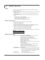
Overview of This Manual
Structure of This Manual
This user’s manual consists of the following chapters.
Chapter
1
Title
Overview
2
Operating Procedure
3
Detailed Description
of Functions
Index
Description
Gives an overview of the GateMODBUS software.
Lists the PC requirements for running Gate-MODBUS and
gives information about system configuration.
Gives procedures for entering environment and data
logging interval settings, and how to monitor the operational
status of the software.
Provides a detailed description of the functions of
GateMODBUS. Lists error messages, their causes, and
their corrective actions.
An alphabetical index of the manual's contents.
Scope of This Manual
This manual does not explain the basic operations of your PC's operating system (OS).
For information regarding the basic operations of Windows, see the Windows user’s
manual.
Conventions Used in This Manual
•
Units
K Denotes 1024.
M Denotes 1024K.
G Denotes 1024M.
Example: 10 KB
Example: 10 MB
Example: 2 GB
• Boldface Type
Hardware and software controls that the user manipulates such as dialog boxes,
buttons, and menu commands are often set in boldface type.
• Subheadings
On pages in chapters 1 through 3 that describe operating procedures, the following
subheadings are used to distinguish the procedure from their explanations.
Procedure
iv
Note
This subsection contains the operating procedure used to carry out
the function described in the current section. All procedures are
written with inexperienced users in mind; experienced users may
not need to carry out all the steps.
Calls attention to information that is important for proper operation
of the instrument.
IM WX1-05E
1
Contents
Software License Agreement............................................................................................................. ii
Overview of This Manual.................................................................................................................. iv
2
Chapter 1 Overview
1.1 Overview of GateMODBUS Functions.................................................................................. 1-1
1.2 System Overview.................................................................................................................. 1-2
3
Chapter 2 Operating Procedure
2.1
2.2
2.3
2.4
2.5
2.6
2.7
Running and Exiting GateMODBUS..................................................................................... 2-1
Entering Environment Settings............................................................................................. 2-2
Saving and Restoring Environment Settings........................................................................ 2-6
Reading Data from a Modbus Device and Transferring the Data as the Monitor Server...... 2-7
Performing the Loop Back Test . .......................................................................................... 2-9
Viewing the Status of the Executable Function and Retrying Communications..................2-11
Viewing Version Information............................................................................................... 2-13
Chapter 3 Detailed Description Functions
3.1 Overview............................................................................................................................... 3-1
Environment Setting Functions............................................................................................. 3-1
Executable Function............................................................................................................. 3-2
3.2 Detailed Description of Functions......................................................................................... 3-3
Communication Port............................................................................................................. 3-3
Modbus Communications..................................................................................................... 3-3
Logical Configuration............................................................................................................ 3-4
Acquisition Conditions.......................................................................................................... 3-4
Groups.................................................................................................................................. 3-5
Acquiring Data at Fixed Intervals.......................................................................................... 3-6
Data Dropout........................................................................................................................ 3-6
Timeout Operation................................................................................................................ 3-7
Resetting the Timeout Counter............................................................................................. 3-7
Data Type............................................................................................................................. 3-8
Data Scaling....................................................................................................................... 3-10
Running/Stopping Executable Function.............................................................................. 3-10
Loop Back Test................................................................................................................... 3-10
Test Acquisition................................................................................................................... 3-10
Monitor Server Function..................................................................................................... 3-10
Status Display of Executable Function............................................................................... 3-10
3.3 Messages and Corrective Actions.......................................................................................3-11
Error.....................................................................................................................................3-11
Message..............................................................................................................................3-11
Executable Function Messages...........................................................................................3-11
Index
IM WX1-05E
Index
Chapter 1
Overview
1.1
1
Overview of GateMODBUS Functions
Features
•
•
•
•
Runs as a Windows application.
Supports the Modbus/RTU (serial) and Modbus/TCP (Ethernet) protocols.
Allows you to read the input and holding registers from various measuring instruments.
Measurement can be performed at intervals of up to 0.5 seconds*.
* However, DAQLOGGER’s shortest interval is 1 second. Also, the maximum speed of 0.5
seconds may not be attainable depending on the amount of data being read, the response
time of the device, and the communication speed.
IM WX1-05E
1-1
Overview
GateMODBUS is a software program that uses the Modbus protocol to acquire data
from other application software or measuring instruments with data output functions,
and transfer the data to DAQLOGGER or Remote Monitor. Using GateMODBUS allows
you to monitor data on DAQLOGGER or Remote Monitor that was acquired not only by
Yokogawa recorders, but also by other manufacturers’ measuring instruments as well.
Yokogawa’s DAQLOGGER is a software program that allows users to open a connection
from their PC to various kinds of Yokogawa recorders (the mR, VR, DARWIN, DX, MV,
and CX) and perform data logging and monitoring.
Yokogawa’s Remote Monitor is a software program that enables monitoring of data
logged by recorders or data logging software.
2
3
Index
1.2
System Overview
System
This software can perform data logging when connected with instruments (devices)
meeting the following criteria.
• The ability to perform communications using the Modbus/RTU (serial) or Modbus/TCP
(Ethernet) protocol.
• For serial communications, the ability to operate under a baud rate of 4800, 9600,
19200, or 38400.
• The ability to read registers using one or both of the following two Modus function
codes.
• Function code 03: read holding registers
(register numbers: 40001-49999, 400001-465535)
• Function code 04: read input registers
(register numbers: 30001-39999, 300001-365535)
Software Requirements
Run DAQWORX under any of the following operating systems.
• Windows 2000 Professional SP4
• Windows XP Home Edition SP3
• Windows XP Professional SP3 (excluding Windows XP Professional x64 Editions)
• Windows Vista Home Premium SP2 (excluding the 64-bit editions)
• Windows Vista Business SP2 (excluding the 64-bit editions)
• Windows 7 Home Premium, SP1 (32-bit and 64-bit editions)
• Windows 7 Professional, SP1 (32-bit and 64-bit editions)
The language displayed by the software under different language versions of the OS are
as follows.
OS Language
Japanese
Other
Software Language
Japanese
English
Hardware Requirements
The following hardware are required to use GateMODBUS.
• PC:A PC that runs one of the OS above, and that meets the
following CPU and memory requirements.
When Using Windows 2000 or Windows XP
Pentium 4, 1.6 GHz or faster Intel x64 or x86 processor; 512MB or more of memory
When Using Windows Vista
Pentium 4, 3 GHz or faster Intel x64 or x86 processor; 2 GB or more of memory
When Using Windows 7
32-bit edition: Intel Pentium 4, 3 GHz or faster x64 or x86 processor; 2 GB or more of memory
64-bit edition: Intel x64 processor that is equivalent to Intel Pentium 4, 3 GHz or faster; 2 GB or more of memory
• Free disk space: 200 MB or more
• Communication device: An Ethernet (when connecting to DAQLOGGER or Remote
Monitor), or RS-232 port that is recognized by the operating
system. Also required for Ethernet communications with this
software’s Modbus instruments), or RS-232 port
• CD-ROM drive: Used to install the software
A mouse supported by the operating system
• Peripheral devices: 1-2
IM WX1-05E
1.2 System Overview
A video card that is recommended for the OS and a display that is supported by the OS, has a resolution of 1024×768 or higher, and that can show 65,536 colors (16-bit, high color) or more.
Note
An RS-232 to RS-422-A/RS-485 converter is required to perform communications between the
software and another Modbus device via RS-422-A/RS-485 (Yokogawa ML2 RS232C/RS485
converter recommended).
1
Overview
• Monitor:
2
3
Index
IM WX1-05E
1-3
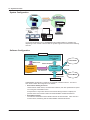
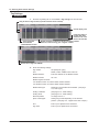
1.2 System Overview
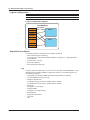
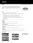
System Configuration
GateMODBUS
TCP/IP connection
Monitor server protocol
Data transfer
Remote monitor
Converter
Ethernet
Ethernet
RS-422-A/RS-485
PV
2
SP
3
4
SP
AL 1
2
3
MAN
A/M
SET/ENT
Modbus/RTU devices
JUXTA
(VJET),
Temperature
controllers
Modbus/TCP devices
It is recommended that you run GateMODBUS and DAQLOGGER on separate PCs
depending on the number of devices that the system supports and other factors affecting
the load.
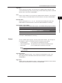
Software Configuration
GateMODBUS
Displays execution
and connection
status
Environment setting
functions
Writes to file
DAQLOGGER
Status information
Executable
function
Environment
settings file
File read out
Modbus/RTU
Modbus/TCP
Ethernet
Ethernet
Remote Monitor
Modbus devices
GateMODBUS Configurator consists of two separate software functions. The role of
each function within the configurator is as follows:
• Environment Setting Functions
Used to define model names, communication methods, and other parameters required
for running the executable function.
And operates in conjunction with the environment setting functions to display the
practice status and connection status of DAQLOGGERs and Remote Monitors.
• Executable Function
The software reads data from the Modbus devices at fixed intervals. It also acts as a
monitor server, transferring data to DAQLOGGER and Remote Monitor.
1-4
IM WX1-05E
Chapter 2
2.1
Operating Procedure
1
Running and Exiting GateMODBUS
Running the Software
2
Procedure
GateMODBUS > GateMODBUS.
Operating Procedure
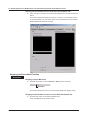
1. From the Windows Start menu, choose Programs > YOKOGAWA DAQWORX >
3
The GateMODBUS Configurator opens.
Index
Note
• When you start GateMODBUS, it is restored to the same status that was active during the
previous session.
• If the program is closed while a process or service is running, the license will be considered to be “in use.”
If the message, “Invalid license number. Please reinstall.” appears when restarting the program, it may
indicate that the user is attempting to run a Gate program in excess of the number of available licenses.
Starting GateMODBUS in Acquisition Start Mode
Procedure
1. From the Windows Start menu, choose Programs > YOKOGAWA DAQWORX >
GateMODBUS > GateMODBUS, then right-click GateMXMW and select Create
Shortcut.
2. Right-click the shortcut icon and select Properties.
3. Choose the Shortcut tab, then add /START to the right of the path in the Target
box and click OK.
4. Choose the shortcut from the Windows Start menu. The connection status of the
previous session is restored, and acquisition begins.
Exiting the Software
Procedure
1. Choose File > Exit from the menu bar, or click the X button at the right end of
the title bar.
IM WX1-05E
GateMODBUS closes.
2-1
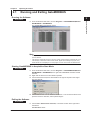
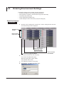
2.2
Entering Environment Settings
The following settings can be entered using the configurator.
• Serial port and Ethernet port settings (Serial Setting tab)
• Data acquisition conditions, communication retry (Scan Interval tab)
• Tag settings (Tag Setting tab)
• Group settings (Group Setting tab)
• TCP/IP settings for the monitor server port (Port Setting tab)
Serial Port Settings
Procedure
1. Click the Comm. Setting tab or choose View > Comm. setting from the menu bar.
The Serial Setting screen in displayed.
Select/deselect
all items
Drag to select a
range of items
Click to display a list
Copies the setting in
the first item of the
selection to all of the
items in the selection
Click to turn a single item ON/OFF
Turns all selected
items ON/OFF
2. Set the port number, baud rate, and parity.
Port number: ON (blue)/OFF (gray)
Baud rate: 4800, 9600, 19200, 38400
Parity: NONE, ODD, EVEN
3. Turn Ethernet ON (blue) or OFF (gray).
4. Click Address. The dialog box below opens.
2-2
IM WX1-05E
2.2 Entering Environment Settings
5. Enter the IP address or host name and port number. (The default port number for
1
Modbus/TCP is 502. Use this port number if no particular setting is required by
the instrument.)
2
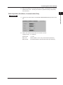
Data Acquisition Conditions, Communication Retry
1. Click the Scan Interval tab or choose View > Scan Interval setting from the menu
bar.
Operating Procedure
Procedure
3
Index
2. Set the scan interval, timeout time, and number of retries.
IM WX1-05E
Logging interval: 0.5–3600 sec.
Timeout time:
1–10 sec.
Retry Use :
Select whether or not to retry communications (ON/OFF).
Retry Interval :
The interval between communication retries (30–3600 sec.)
2-3
2.2 Entering Environment Settings
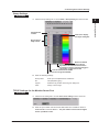
Tag Settings
Procedure
1. Click the Tag Setting tab or choose View > Tag setting from the menu bar.
Drag to select a range of items (up to 300 channels can be selected)
Click to display a list
Copies the setting in
the first item of the
selection to all of the
items in the selection
Turns all selected
items ON/OFF
Register numbers are filled from the first cell in the selection
to the last, each line being given a register number 1
Select/deselect all items
Click to turn a single item ON/OFF
2. Enter the following settings.
Tag number: ON (blue)/OFF (gray)
Port: NONE, COM1–COM9, Ether1–Ether16
Modbus address: Enter the address for the Modbus device.
Modbus function: 03 or 04
Modbus register numbers:
For Modbus function 03, 40001-49999, 400001-465535
For Modbus function 04, 30001-39999, 300001-365535
2-4
Modbus data type: Depends on the Modbus device header. (See page
3-8, “Data Type”)
Scaling coefficient: (See page 3-10, “Data Scaling”)
Scaling offset: (See page 3-10, “Data Scaling”)
Decimal position: An integer from 0–4
Span Lower/Upper: Setting range varies depending on the decimal
position. (See page 3-5, “Upper/Lower Limit of Span”)
Unit:
Enter up to 6 alphanumeric characters.
Tag name:
Enter up to 16 alphanumeric characters.
IM WX1-05E
2.2 Entering Environment Settings
1
Group Settings
Procedure
1. Click the Group Setting tab or choose View > Group setting from the menu bar.
2
Operating Procedure
3
Select/deselect
all items
Click here to display
the Tag No. dialog box.
Drag to select a
range of items
Restore the default
color to all tags
Tag numbers are filled from the first cell in
the selection to the last, each line being given
a tag number 1 higher than the last
Turns all selected items ON/OFF
Click to turn a single item ON/OFF
2. Enter the following settings.
Group name: Enter up to 30 alphanumeric characters.
No.: ON (blue)/OFF (gray)
Tag No.: Select the tag number in the Tag No. dialog box.
Color: Assign colors to tags.
TCP/IP Settings for the Monitor Server Port
Procedure
1. Click the Port Setting tab or choose View > Port setting from the menu bar.
2. Enter the port number used to transfer data loaded from a Modbus device to
DAQLOGGER or Remote Monitor. The port number need not be changed
unless a problem occurs.
IM WX1-05E
2-5
Index
2.3
Saving and Restoring Environment Settings
Saving Environment Settings
Procedure
1. Click the Save button or choose File > Save from the menu bar.
Save button
The current settings are saved.
Restoring Environment Settings
This procedure clears all settings currently being entered and restores the most recently
saved settings.
Procedure
1. Choose File > Revert from the menu bar.
2-6
IM WX1-05E
2.4
1
Reading Data from a Modbus Device and
Transferring the Data as the Monitor Server
Note
The maximum number of DAQLOGGERs or Remote Monitors that can be connected at once is
16.
Running the Executable Function
Procedure
1. Enter environment settings. (See section 2.2, “Entering Environment Settings.”)
Running from the Menu Bar
2. To run the function as a process, click the Process Execution button or choose
Execute > Process from the menu bar.
IM WX1-05E
Process execution button
Service execution button
To run the function as a service, click the Service execution button or choose
Execute > Service from the menu bar.
The Practice Status item in the Practice/Status tab displays “Process” or “Service,”
as well as the name of the connected client, connection status, and the addresses
of any disconnected DAQLOGGERS and Remote Monitors.
2-7
2
Operating Procedure
When you run the executable function, data is read in from the Modbus devices, the PC
becomes the monitor server, and data is transferred to DAQLOGGER or Remote Monitor.
The executable function can be run as a process or a service. When run as a process,
the executable function closes when logging off Windows. When run as a service, the
executable function is registered in Windows as an automatically executable service.
When run as a service, the executable function continues processing even when the
user has logged off of Windows. Also, the executable function is run automatically as
soon as the PC is turned ON (prior to log in). However, the software can only be run as a
service by a user with Administrator privileges. Services cannot be executed when using
Windows Vista.
3
Index
2.4 Reading Data from a Modbus Device and Transferring the Data as the Monitor Server
Running the Executable Function from the Practice/Status Tab
2. Select the type of execution from the Practice/Status tab, then click the Practice
button.
The Practice Status item displays “Process” or “Service,” as well as the names
of connected clients, the connection status, and the addresses of disconnected
DAQLOGGERS and Remote monitors.
Stopping the Executable Function
Procedure
Stopping from the Menu Bar
1. Click the Stop button or choose Execute > Stop from the menu bar.
Stop button
The Practice Status item shown on the Execution/Status tab displays “Stop.”
Stopping the Executable Function from the Execution/Status Tab
1. Click the Stop button on the Execution/Status tab.
2-8
“Stop” is displayed for the practice status .
IM WX1-05E
2.5
1
Performing the Loop Back Test
Performing the Loop Back Test
2
Operating Procedure
Note
The loop back test or service cannot be performed while other processes or a services are
running.
3
Procedure
Index
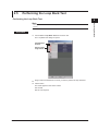
1. Choose Test > Loop Back Test from the menu bar.
The Loop Back Test dialog box opens.
Select/deselect
all items
Drag to select a
range of items
2. Drag to select the addresses on which you wish to perform the loop back test.
3. Click Practice.
IM WX1-05E
The result appears in the status column.
OK: Normal
Not OK: No response
2-9
2.5 Performing the Loop Back Test
Executing the Test
Procedure
Starting the Test
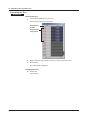
1. Choose Test > Test from the menu bar.
The Test Exec dialog box is displayed.
Select/deselect
all items
Drag to select a
range of items
2. Drag to select the tag numbers on which you wish to perform the test.
3. Click Practice.
The scaled result is displayed.
Stopping the Test
4. Click STOP.
2-10
The test stops.
IM WX1-05E
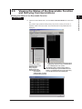
2.6
Viewing the Status of the Executable Function
and Retrying Communications
Viewing the Status of the Executable Function
2
Procedure
bar.
Operating Procedure
1. Click the Practice/Status tab or choose View > Execution/Status from the menu
1
3
The practice type, practice status (running as process, running as service, or
stopped), client connection status, and communication cutting addresses are
displayed.
Index
If Use retry is turned OFF on the Scan Interval
The practice status is
Setting tab, click here to retry communication
displayed using colors
if a communication error occurs.
Green: Normal
The software retries communication until it is
Gray: Stopped
restored and displays up to 200 addresses that
Blinking red: Error
ended in a communication error only if Use retry
Yellow: Data dropout
is turned ON the Scan Interval Setting tab
occurred and
communication is retried
(communication paused)
IM WX1-05E
2-11
2.6 Viewing the Status of the Executable Function and Retrying Communications
Note
• Click the Start button to download data from the Modbus devices. The interval at which data
is downloaded is determined by the data acquisition conditions (scan interval, timeout time,
and number of retries).
• If a warning message is displayed (code Wxxxx), the lamp that displays the connection
status by color does not blink red.
• When an error occurs and the lamp blinks red, the Error Indicator dialog box appears. If you
close the dialog box, the lamp turns green.
Retrying Communications
1. Click the Communication Retry button.
2-12
Retries communications. (Retry time)
IM WX1-05E
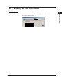
2.7
1
Viewing Version Information
Procedure
2
1. Click the About button or choose Help > About from the menu bar.
Operating Procedure
The Version dialog box opens.
3
Version
Index
Company name
User name
License number
IM WX1-05E
2-13
Chapter 3
3.1
Detailed Description Functions
1
Overview
GateMODBUS performs serial communications with Modbus devices and acquires data
at regular intervals. Through the monitor server function, the acquired data is transferred
to DAQLOGGER or Remote Monitor via Ethernet. The following is a list of the features
of each software function.
3
Environment Setting Functions
Index
• Serial Port Settings
Baud rate
Parity
• Ethernet port to be used
IP address or host name
Port number
• Data Acquisition Conditions
Scan interval
Timeout time
Retries
• Tag Settings
Communications port
Modbus address
Modbus function
Modbus register number
Modbus data type
Scaling coefficient
Scaling offset
Decimal place
Upper/lower limit of span
Unit
Tag name
• Group Settings
Tag assignments
Tag colors
Group name
• TCP/IP Settings for the Monitor Server Port
• Running/Stopping Executable Function
Running of the executable function as a service
Running of the executable function as a process
Stopping the executable function
• Performing Tests (Data Acquisition)
• Loop Back Test
•Communication Retry ON/OFF for the Executable Function, Retry
Interval, and Reset
• Status Display of Executable Function
Practice status display (stopped, running as a service, running as a process)
The client connection status is displayed if DAQLOGGER or Remote Monitor is the
client.
IM WX1-05E
Detailed Description Functions
Environment setting functions are used to enter all environment settings required to run
the executable function, and are also used to run/stop the executable function.
2
3-1
3.1 Overview
Executable Function
Features of the executable function are as follows:
• Running as a process and as a service is possible.
• Data is acquired from Modbus devices at regular intervals.
• Retries communications.
• Runs as a monitor server if DAQLOGGER or Remote Monitor is the client.
3-2
IM WX1-05E
3.2
1
Detailed Description of Functions
2
Communication Port
The communications ports available to GateMODBUS are the COM1–COM9 serial
(RS-232) ports the Ether1 to Ether16 Ethernet ports. The following items are specified in
the Serial Setting tab.
Serial port setting
Index
Ethernet port setting
• IP address or host name
• Password
Note
The Modbus protocol’s RTU (remote terminal unit) mode prescribes stop bit 2 for no parity, and
stop bit 1 for odd or even parity.
Modbus Communications
GateMODBUS supports communications using the Modbus/RTU (serial) and Modbus/
TCP (Ethernet) protocols. The functions and registers used by GateMODBUS for data
logging are as follows:
Function
Description
Register numbers that can be loaded:
03
Read holding register
40001–49999
30001–39999
04
Read input register
400001–465535
300001–365535
Also, you can execute the following functions on the configurator to display the
connection status with Modbus devices.
Function
Sub-function
Description
08
00
Loop back test
Note
GateMODBUS does not support the Modbus protocol’s Modbus/ASCII mode.
IM WX1-05E
Detailed Description Functions
• Baud rate (4800, 9600, 19200, or 38400 bps)
• Parity (None, Even, or Odd)
3
3-3
3.2 Detailed Description of Functions
Logical Configuration
Item
Tag
Group
Description
Indicates one data item.
Assigns tags. Up to 32 tags can be assigned to a group.
Limit
300
50
Logical Configuration Diagram
GateMODBUS
TAG001
TAG002
Assignments
Group
TAG003
TAG004
Tag
Group
TAG200
Acquisition Conditions
The following items are included in the acquisition conditions.
• Data scan interval (0.5–3600 sec)
For information on the data acquisition operation, see page 3-6, “Acquiring Data at
Fixed Intervals.”
• Timeout time (1–10 sec)
• Retry Use (ON/OFF).
• Retry Interval (30–3600 sec.)
Tag
A tag is a name for a data value. You can use up to 100 tags with GateMODBUS. Data
obtained from the Modbus registers is assigned to each tag. The following items are
included in tag settings.
• Used serial ports (COM1–COM9) and Ethernet ports (Ether1 to Ether16)
• The read Modbus function (03 or 04)
• Register numbers read
For Modbus function 03: 40001–49999, 400001–465535
For Modbus function 04: 30001–39999, 300001–365535
• Data Type
See page 3-8, “Data Type.”
• Scaling variable
See page 3-10, “Data Scaling.”
• Decimal place
• Upper/lower span value
• Tag name
• Unit
3-4
IM WX1-05E
3.2 Detailed Description of Functions
Tag Name
Enter a tag name as needed. You can enter up to 16 alphanumeric characters. Tags
can be downloaded (tag data is received) using a DAGLOGGER tag software or Remote
Monitor that is connected to GateMODBUS.
1
2
Unit
Enter a unit as needed. You can enter up to 6 alphanumeric characters. The unit string
is the unit string on the DAQLOGGER or Remote Monitor connected to GateMODBUS.
Enter a decimal place of 0, 1, 2, 3, or 4. This value is the decimal place used when
DAQLOGGER or Remote Monitor is connected to Gate-MODBUS for monitoring.
Index
Upper/Lower Limit of Span
Enter the upper and lower limit values of span. The available setting range is as follows:
Decimal Place
0
1
2
3
4
Setting Range
–10000000000000000 to 10000000000000000
–1000000000000000.0 to 1000000000000000.0
–100000000000000.00 to 100000000000000.00
–10000000000000.000 to 10000000000000.000
–1000000000000.0000 to 1000000000000.0000
This value is the default setting used when DAQLOGGER or Remote Monitor is
connected to GateMODBUS for monitoring.
Groups
You can combine tags into groups. Up to 50 groups can be created. Up to 32 tags can
be assigned to a group. The following items are included in group settings.
• Tag assignments: Up to 32 tags can be assigned to a group.
• Color of assigned tags: The default color when connected to Remote Monitor.
• Group name: Up to 30 alphanumeric characters can be input.
Note
Group settings cannot be used by DAQLOGGER. They are only available when connected
to Remote Monitor.
Tag Assignments
Tags can be assigned to groups. Up to 32 tags can be assigned to a group. The
tags assigned here are the default values when Remote Monitor is connected to
GateMODBUS.
Tag Colors
Specify colors for tags assigned to groups. The tag colors specified here are the default
values when Remote Monitor is connected to GateMODBUS.
IM WX1-05E
Detailed Description Functions
Decimal Place
3
3-5
3.2 Detailed Description of Functions
Group Names
You can assign names to groups. Names can contain up to 30 alphanumeric characters.
The group names specified here are the default values when Remote Monitor is
connected to GateMODBUS.
Acquiring Data at Fixed Intervals
Using GateMODBUS, data can be acquired concurrently on each port. Therefore
data is logged more efficiently when connecting each Modbus device to a separate
port rather than connecting several Modbus devices to a single port. Also, registers
occurring in a continuous sequence on 1 instrument are read all at once. Therefore, the
more sequentially continuous registers there are, the more efficiently data is acquired.
However, if a register within the sequence experiences an error, the error applies to all
registers in the sequence.
For example, given the three registers below, TAG001–TAG003 are read all at once at
each scan interval.
Tag
TAG001
TAG002
TAG003
COM Port
COM1
COM1
COM1
Modbus Address
1
1
1
Register numbers read
30001
30002
30003
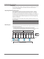
Data Dropout
If data is being read at the timing shown below, data is dropped. Data dropout can occur
in the following circumstances.
• If the time required to read the tags is longer than the scan interval
In the figure below, by the time the tags at T1 have been read, T2 has already passed
and T3 begins. Therefore, the tags to have been read at T2 were dropped.
Data reading at time T
Data reading at time T1
TAG001 TAG002 TAG003 TAG004 TAG001 TAG002 TAG003 TAG004
Data
dropout
occurs
Time
Time
T
Interval: ∆T
T1 = T + ∆t
T2 = T + ∆t x 2
T3 = T + ∆t x 3
Timing of Data Reading
3-6
IM WX1-05E
3.2 Detailed Description of Functions
In this case, as much time as possible must be given to interval ∆T to acquire all tags
assigned to the port.
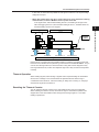
• When data reading times out due to such instances as noise interference during
communication, or when a Modbus device’s power turns OFF
In the figure below, with the data reading at time T, the reading of all tags occurs
within the logging interval ∆T, but with data reading at time T1, TAG0003 times out,
and data reading at time T2 is dropped.
TAG001
Data
dropout
occurs
TAG001
TAG002
TAG002
TAG003 times out
TAG003
TAG004
TAG004
Time
Time T
Interval: ∆T
T1 = T + ∆t
T2 = T + ∆t x 2
T3 = T + ∆t x 3
Timing of Data Reading
Enter as short of a timeout time as possible, keeping in mind the processing power and
baud rate of the Modbus device performing communications with GateMODBUS. As you
can see from the figure above, if the timeout time is long data can be dropped not only
from tags that timed out, but also from adjacent tags even if they would have responded
normally.
Timeout Operation
When reading tag data, after sending a register value request message to the Modbus
device, if the message is not received within the specified timeout time that tag is
considered to have timed out. When the setting of “Retry Use” is turning on, retrying is
executed for tag which have timeout.
Resetting the Timeout Counter
You can reset the timeout counter for the executable function from the configurator.
When resetting the timeout counter, the retries of tags for which data acquisition was
stopped due to the executable function having timed out begin again at 1, and data
reading is performed.
IM WX1-05E
3-7
2
3
Detailed Description Functions
Data reading at time T1
Data reading at time T
1
Index
3.2 Detailed Description of Functions
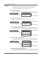
Data Type
With the Modbus protocol, the data type within the read registers is not defined.
Therefore, the data type in the read registers depends on the Modbus device’s
manufacturer. GateMODBUS supports the following data types.
Signed 16–Bit Integer (INT16)
Enter this setting if a signed 16–bit integer is assigned to the Modbus device registers.
GateMODBUS tag data
Modbus registers
Signed 16–bit
Register number (small)
Register number (large)
Unsigned 16–Bit Integer (UINT16)
Enter this setting if an unsigned 16–bit integer is assigned to the Modbus device
registers.
GateMODBUS tag data
Modbus registers
Register number (small)
Unsigned 16–bit
Register number (large)
Signed 32–Bit Integer High/Low (INT32_B)
Enter this setting if a signed 32–bit integer is assigned to the Modbus device registers
and the register numbers are assigned from high to low starting with the smallest register.
GateMODBUS tag data
Modbus registers
Register number (small)
Signed 32–bit integer (high)
Signed 32–bit integer (low)
Register number (large)
Signed 32–Bit Integer Low/High (INT32_L)
Enter this setting if a signed 32–bit integer is assigned to the Modbus device registers
and the register numbers are assigned from low to high starting with the smallest register.
GateMODBUS tag data
Modbus registers
Register number (small)
Signed 32–bit integer (low)
Signed 32–bit integer (high)
Register number (large)
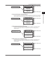
Unsigned 32–Bit Integer High/Low (UINT32_B)
Enter this setting if an unsigned 32–bit integer is assigned to the Modbus device registers
and the register numbers are assigned from high to low starting with the smallest register.
3-8
IM WX1-05E
3.2 Detailed Description of Functions
GateMODBUS tag data
Modbus registers
Register number (small)
Unsigned 32–bit
integer (high)
Unsigned 32–bit
integer (low)
2
Register number (large)
Enter this setting if an unsigned 32–bit integer is assigned to the Modbus device registers
and the register numbers are assigned from low to high starting with the smallest register.
Modbus registers
Register number (small)
Unsigned 32–bit
integer (low)
Unsigned 32–bit
integer (high)
Register number (large)
32–Bit Floating Point High/Low (FLOAT_B)
Enter this setting if an unsigned 32–bit floating point is assigned to the Modbus device
registers and the register numbers are assigned from high to low starting with the
smallest register.
GateMODBUS tag data
Modbus registers
Register number (small)
32–bit floating point (high)
32–bit floating point (low)
Register number (large)
32–Bit Floating Point Low/High (FLOAT_L)
Enter this setting if an unsigned 32–bit floating point is assigned to the Modbus device
registers and the register numbers are assigned from low to high starting with the
smallest register.
GateMODBUS tag data
Modbus registers
Register number (small)
32–bit floating point (low)
32–bit floating point (high)
IM WX1-05E
Register number (large)
3-9
3
Detailed Description Functions
Unsigned 32–Bit Integer Low/High (INT32_L)
GateMODBUS tag data
1
Index
3.2 Detailed Description of Functions
Data Scaling
There are times when the values obtained by reading registers during Modbus
communication are not physical values.
GateMODBUS performs the following calculations on Modbus register values.
X=A•x+B
X:calculated result
x: Modbus register value
A:Coefficient
B:Offset
The user can specify a desired value for coefficient A and offset B above using the
configurator.
Running/Stopping Executable Function
The configurator starts and stops the executable function. There are two execution
methods, process and service. Process execution starts the application as any normal
program. When started as a process, the executable function closes when logging off
Windows. When started as a service, the executable function is registered in Windows
as an automatically executable service. When started as a service, the executable
function continues processing even when the user has logged off of Windows. Also,
the executable function is run automatically as soon as the PC is turned ON (prior to log
in). However, the function can only be run as a service when using Windows 2000 or
Windows XP by a user with Administrator privileges. Services cannot be executed when
using Windows Vista.
Loop Back Test
Using the configurator, you can perform the Modbus function 08 loop back test on
each Modbus device connected to GateMODBUS. This sub-function is 00, and during
normal operation, data having the same contents as data sent to the Modbus device
by GateMODBUS is returned from the Modbus device. The result of the loop back test
is displayed as either Normal or No Response on the configurator. If the loop back test
results in no response, it may indicate a problem with the communication cable, baud
rate or parity mismatch, or a wrong Modbus address.
Test Acquisition
You can perform a test acquisition on each tag using the configurator. For the test
acquisition, data is read from the registers of the Modbus devices specified for each tag,
the results are scaled per specified values and displayed as digital values. From this,
you can determine whether the COM port, Modbus address, Modbus register, scaling
coefficient, and decimal place for each tag is correct.
Monitor Server Function
GateMODBUS takes data read in from the Modbus devices and utilizes its monitor server
functionality to transfer the data to DAQLOGGER or Remote Monitor. The maximum
number of DAQLOGGERs or Remote Monitors that can be connected at once is 16.
Status Display of Executable Function
The status display function allows you to display the following status items for the
executable function.
• Practice status (stopped, running as a service, running as a process)
• Tags disconnected due to timeout
• PCs connected to DAQLOGGER and Remote Monitor as a monitor server
3-10
IM WX1-05E
3.3
1
Messages and Corrective Actions
Error
Message
Cannot write to file.
Cannot read file.
E213
Cannot open file.
E401
Communication error.
E402
E403
E1010
Communication timeout.
Cannot open a communication
port.
Invalid license number. Please
reinstall the software.
Execution of a process failed.
E1011
Execution of a service failed.
E501
Corrective Actions
Check if the disk capacity is sufficient or if the file systems is normal.
Check if the file exists and is supported by the software or if the file system is
normal.
Check if the file exists and is supported by the software or if the file system is
normal
Check if the recorder connected for communication is powered on and if the
cable is properly connected. Also check the following items according the
communication type.
• For Ethernet
Check if address settings are correct; the TCP/IP protocol is installed in
Windows; the Ethernet card is properly installed.
• For RS-232 and RS-422-A
Check if the baud rate settings match; the port (COM1 to COM9) settings
match, the address settings are correct (RS-422-A); the serial port of the PC
is active and the appropriate cable is being used.
Same as E401.
Install the software again.
Check whether an executable function exists, or whether its files are
damaged. If this error appears frequently, reinstall the software.
Check whether an executable function exists, or whether its files are
damaged. If this error appears frequently, reinstall the software.
Message
No.
M1201
M1210
Message
Model determination was successful.
Setting changes saved before execution.
Executable Function Messages
No.
W[631]
Message
Data Lack
E[673]
E[674]
E[675]
E[800]
E[801]
E[802]
E[804]
I[606]
Cannot open communication
Communication error
Communication time out
CRC check error
Invalid handle.
Error respond
Invalid command
Recovery Communication
IM WX1-05E
Corrective Actions
Reduce the number of acquired data points or connected instruments, or
lengthen the scan interval.
Same as E401.
Same as E401.
Same as E401.
A CRC error was detected. Check the communication status.
Check the communication status.
Check the communication status.
Connection recovered.
3-11
2
3
Detailed Description Functions
No.
E211
E212
Index
Index
1
Index
A
S
acquiring data at fixed intervals............................................. 3-6
acquisition conditions............................................................ 3-4
saving environment settings.................................................. 2-6
serial port............................................................................... 3-3
Serial Port Settings................................................................ 2-2
software configuration........................................................... 1-4
software license......................................................................... ii
status display of executable function................................... 3-10
stopping executable function............................................... 3-10
stopping the executable function........................................... 2-8
system................................................................................... 1-2
system configuration............................................................. 1-4
C
client connection status........................................................ 2-11
communication cutting addresses........................................ 2-11
D
E
Entering Environment Settings.............................................. 2-2
environment setting functions......................................... 1-4, 3-1
Ethernet port to be used........................................................ 3-1
executable function........................................................ 1-4, 3-2
executing the test................................................................ 2-10
exiting the software............................................................... 2-1
T
tag......................................................................................... 3-4
tag assignments.................................................................... 3-5
tag colors............................................................................... 3-5
tag name............................................................................... 3-5
Tag Settings........................................................................... 2-4
TCP/IP settings...................................................................... 2-5
test acquisition..................................................................... 3-10
timeout operation................................................................... 3-7
U
G
unit......................................................................................... 3-5
upper/lower limit of span....................................................... 3-5
group names......................................................................... 3-6
groups................................................................................... 3-5
Group Settings...................................................................... 2-5
V
version information.............................................................. 2-13
H
hardware requirements......................................................... 1-2
L
logical configuration............................................................... 3-4
Loop Back Test...................................................................... 2-9
loop back test...................................................................... 3-10
M
message............................................................................... 3-11
Modbus communications....................................................... 3-3
monitor server function........................................................ 3-10
O
Overview............................................................................... 3-1
overview of functions............................................................. 1-1
P
port number........................................................................... 2-5
practice status...................................................................... 2-11
R
resetting the timeout counter................................................. 3-7
restoring environment settings.............................................. 2-6
retrying communications..................................................... 2-12
running executable function................................................ 3-10
running the executable function............................................ 2-7
running the software.............................................................. 2-1
IM WX1-05E
Index-1
3
Index
Index
data acquisition conditions.................................................... 2-3
data dropout.......................................................................... 3-6
data scaling......................................................................... 3-10
data type................................................................................ 3-8
decimal place........................................................................ 3-5
2