1
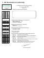
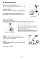
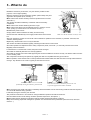
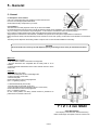
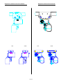
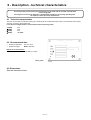
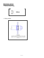
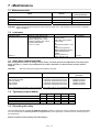
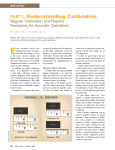
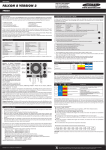
C.H.V
INSTALLATION
MAINTENANCE
SPARE PARTS
ANGLAIS
VARIABLE SPEED ELECTRIC TROLLEY TYPE CHV
VERLINDE reserves the right to alter or amend the above information without notice
04/02 VESEGBCHVA
Table of contents
Read the instructions supplied with the travelling machinery unit before installation and commissioning.
Keep the instructions in a safe place for future reference.
PART 1
OWNER'S MANUAL FOR NORMAL HEADROOM TROLLEY
page
1 "EC" Declaration of conformity
1
2 What not to do
2
3 What to do
3
4 Guarantee
4
5 General
5-1 Acceptance of the material
5-2 Installation
5
5
6 Description - technical characteristics
6-1
6-2
6-3
6-4
Technical characteristics
Environmental data
Dimensions and weight
Adjustment of flanges
7
7
7
8
7 Maintenance
9-1
9-2
9-3
9-4
9-5
Maintenance table
Lubricants
Spare parts replacement table
Tightening torques
Discarding the trolley
10
10
10
10
10
8 Illustrated catalogue
11-1 Electric trolley
PART 2
11
OWNER'S MANUAL FOR TRAVELLING MACHINERY
9707
1 - EC Declaration of conformity
VERNOUILLET
France
As defined by the EC directive relating
to machinery 98/37/EEC.
Annex II A
Herewith, we declare that the product :
Wire rope hoist
Belt hoist
Electric chain hoist
Manual chain hoist
Electric trolley
Manual winch
z
z
z
z
z
z
z
z
z
z
z
z
z
z
z
Complies with the following provisions applying to it:
- Machinery directive 98/37/EEC.
- Directive 2006/95/CEE.
- "EMC" Directive 89/336/EEC
Applied harmonized standards, in particular:
- EN 60204-32,
- EN ISO 12100-1 and 12100-2
z
z
z
z
z
z
z
z
z
z
z
z
z
z
National regulations, standards and specifications:
- order of March 1st 2004
- DIN 15400; DIN 15401,
Quality system applied:
- EN29001/ISO9001
z
z
z
z
z
z
z
z
z
z
z
z
z
z
z
z
z
z
z
z
z
z
z
z
z
z
z
z
Technical standards and specifications complied with, in particular:
- FEM 9.511
"classification of the mechanisms".
- FEM 9.661
"dimensions and quality of the drive and cable lifting block
elements for mass-produced lifting devices".
- EN 818
"chain quality, choice criteria and technical requirements".
- FEM 9.683
"choice of motors".
- FEM 9.755
"steps to be taken to determine the operating periods for massproduced motorized lifting mechanisms (S.W.P.)".
- FEM 9.751
"Motorized lifting mechanism: safety"
- FEM 9.901
"bases of design for the mass-produced lifting devices
for travelling cranes equipped with mass-produced lifting devices".
2007/04
Bernard DELEFOSSE
2 - What not to do
Never move or lift the machine by the electric cables.
Do not set down the machine without having an adapted support, to avoid
damaging the sensitive sides.
Do not let the machine drop.
Never modify the machine unless the constructor has studied and
authorized the modification.
Never modify the values and adjustments of the safety components,
outside the limits provided for in the manual, or without the approval of the
constructor.
Never try to repair or intervene on the machine (welding...) without the
authorization of the constructor or a trained maintenance agent.
Never shunt the disconnect switches, electric switches, prevention or
limitation equipment.
Do not let an unqualified person use the machine.
Do not let an unqualified
person use the machine.
Never lift more than the maximum working load indicated on the machine. Shocks or accidental collision of the load with
objects can cause excess loads.
Never remove the hook safety catches.
Never block, adjust or remove the limit switches or stops to go further to the left or right than these allow.
Never use the machine to extract, loosen, or pull sideways.
Never use the machine to transport people.
Do not touch the moving components.
Do not operate the machine if your physical condition does not allow it.
Never use the machine when in bad repair (wear, deformation...).
Never use suspect spare parts or parts whose origin is not known.
Never swing the load intentionally.
Do not subject the machine to brutal shocks.
Do not use the mechanical stops as a repetitive means of stopping.
Never distract the operator while the machine is being operated.
Never leave a suspended load hanging, if it is not necessary.
Never swing the load intentionally.
Never use the machine as an earth reference for welding.
Do not use the machine for a purpose or in an area for which it is not
intended.
Do not expose the machine to an aggressive atmosphere (temperature,
acidity... Refer to 6.2: Environmental data).
Do not use the safety components as operation components.
Do not use the controls needlessly (avoid inching - stop-start operation of
the buttons). This can cause overheating and even damage to the
machine.
Never pull the load slantwise. Make sure that the machine is vertical to the
load before lifting it.
Do not use the machine with a power supply that is different to the one
recommended (undervoltage or overvoltage, absence of phase...).
Never transport a load with people nearby. Do not pass the machine, with
or without a load, above a person.
9707 / 2
Never pull the load slantwise.
3 - What to do
Handle the machine by its structure, or by the devices provided for this
purpose, or in its original packing.
Store the machine in its normal operating position (without load) away from
aggressive atmospheres (dust, humidity...).
Make sure that the machine is always clean and protected from corrosion
(lubrication...).
The machine should be installed by a technician with the necessary
competence.
Make sure that the machine attaching structure is rigid.
Make sure that the safety rules are followed (harness, clearance of work
areas, posting up of instructions to be followed in the area...).
Neutralize the power sources.
Comply with the distance between the trolley and the raceway.
Connect the feed cable directly to the supply terminal board in the electric
box.
Make sure that the machine is always clean.
Set up an inspection program and record all of the maintenance operation for the machines, in particular: the brake, limit
switches, fastening beam...
Replace any element that is worn or may be defective.
The machine should be maintained regularly, following the instructions in this manual.
Check the operation and adjustment of the safety components (brake, travel limit...) in conformity with the user manual.
Regularly check the machine.
If a deformation or unusual wear is noted, the parts must be changed.
Check that the assembly elements are correctly tightened.
Check that the strands of the steel cable supporting the control box fulfill their functions correctly. The electric cable of the box
is not a handling cable.
The components should only be replaced by original parts that are compatible with the type of machine.
Before operation, check that the load is correctly fastened and installed. Make sure that the load is correctly balanced before
moving it. Pay attention to the center of gravity of the load to be moved.
Material used outdoors should be protected as well
as possible against bad weather conditions.
If manually moving the machine, push the load.
When moving the load, make sure that it is sufficiently raised and distant from the surrounding machines and other objects so
as to avoid all obstacles during operation.
If manually moving the machine, push the load.
The prevention instructions to be carried out during the different operations should be well known.
Use the material under normal working conditions (ambient temperature, atmosphere...).
Material used outdoors should be protected as well as possible against bad weather conditions.
Notify the necessary people after a dangerous operation or if the machine seems problematic (abnormal noise, abnormal
behavior...).
9707 / 3
4 - Guarantee
Our electric trolleys are guaranteed for two years from the
date of delivery.
If for a reason outside the control of the vendor, the delivery
is delayed, the time lag cannot exceed three months.
If the use (installation) of the machine is delayed, the
corresponding extension of the guarantee (a single
extension limited to three months) must be requested, and
written confirmation obtained.
The vendor undertakes to eliminate all operating errors
originating from the concept, the execution, the components
or the materials themselves.
The guarantee does not cover normal wear*, nor the
failures resulting from lack of regular and periodic
maintenance. It does not cover damage due to a lack of
supervision, to false operation or to a bad utilization of
the machines, particularly due to overload conditions,
slantwise drawing, undervoltage or overvoltage or a
connection error.
The guarantee does not apply when there is disassembly,
modification or replacement of parts (mechanical or
electrical) by an unauthorized party or without our prior
agreement.
The guarantee only applies for original, factory-installed
spare parts.
For the duration of the guarantee, the vendor undertakes to
replace or repair, free of charge, the parts that are
acknowledged to be damaged following examination by a
qualified and authorized technical service.
The guarantee excludes any other services or indemnities.
The repairs covered by the guarantee are carried out, as a
rule, in the workshops of the vendor or authorized agent.
When servicing of the equipment is done outside these
workshops, the labor costs for disassembly or assembly of
these parts are borne by the vendor when these are done
exclusively by his staff or by an authorized agent. The
replaced parts become the property of the vendor and must
be returned to the vendor at his expense.
For components of a relative particular importance that are
not manufactured by the vendor and which carry the brand
name of specialized manufacturers, the manufacturer’s
guarantee (which can vary according to the manufacturer) is
applicable.
* The guarantee does not apply for expendable parts
defined by the manufacturer:
- Brake disk
- Brushes
- Drive pinion
- Rubber buffer
- Rollers
- Guides
9707 / 4
5 - General
5 - General
5-1 Acceptance of the material
Carry out a visual inspection of the packing to ensure that it is intact.
If it is not, issue the appropriate notifications.
Check that the trolley corresponds to your order.
5-2 Installation
The service life of a trolley depends on the way in which it is installed.
It is essential that the instructions in this manual are followed carefully for the installation, use, and maintenance of your machine.
Any use contrary to our instructions may be dangerous. In this case, the manufacturer will not accept any liability.
Do not use the machine without having read and understood the whole of the instruction manual.
Always keep the manual close to the machine, available to the operator and to the person responsible for maintenance.
Make sure that the safety rules are followed (harness, clearance of work area, posting of instructions to be followed in the work area,
etc.).
The trolley can be adapted to all runaway profiles. Couple or hook on the hoist after installation of the trolley.
CAUTION
Check the width of the runaway rail and adapt the spacing of the flanges of the trolley as indicated in the tables
Make sure:
* That the profile is secured.
* That the profile is suitable to the loads to be supported.
* That the dimensions are compatible with the trolley which is to be
installed.
* That the electrical characteristics of the mains network conform to those
of the motor.
Carry out:
1 - Disassembly of the trolley
* Remove the side plate on the counterweight side
* Position the trolley on the beam
* Refit the side plate.
Check that all the nuts are correctly tightened.
(see 7-4: Tightening torques)
2 - Without disassembly of the trolley:
- Instal the trolley on the profile, by the end
* Fit the travel limit stops (not provided) at the end of the runway.
Check that all the nuts are correctly tightened.
(see 7-4: Tightening torques)
On the curved profiles, the driving wheels should for preference be
positioned on the outside of the curve.
Y + Z = 4 mm MAXI
VERY IMPORTANT!
The total play on the same side, between the driving
rollers and the edge of the profile, must not exceed 4 mm.
0402/5
Suspension with VL1-VL5-VL10-models
1 fall
Suspension with VL16-VL20-VL25
2 falls
1 fall
0215/6
2 falls
6 - Description - technical characteristics
The trolley which you have just purchased should only be used with the nominal load indicated
on the rating plate.
The length of its service life depends on the demands placed on it, the average operating time,
the number of start-ups and its maintenance
6-1 Technical characteristics
The NHT can be used for loads from 250 kg up to 5000 kg with all our electrical chain hoists. It can be drived with a inverter
drive unit or a dual or single speed unit.
It can drive on straight trucks or curved trucks with the following radius:
<1000kg
≤2000kg
≤3200kg
≤5000kg
2m
2m
2m
no radius
6-2 Environmental data
•
•
Ambient temperature:
Protection degree:
-20°C to +40°C
IP55 as standard
Impact on the environment:
• Sound level:
70 decibels at 1 metre
Rating plate
6-3 Dimensions
See the dimension sheet
0215 /7
6-4 Adjustment of the flanges
C1
≤1000
C2
≤2000
C3
≤3200
C5
≤5000
4
64
66
72
73
74
81
82
89
90
91
98
100
106
108
110
113
118
119
120
125
126
131
133
135
137
140
143
146
147
149
150
155
158
160
166
168
170
178
180
185
186
188
190
198
200
206
210
215
218
220
226
240
248
260
268
280
288
300
302
303
304
305
306
307
308
309
310
225
270
320
370
430
4
6
14
16
18
22
24
30
30
32
36
40
0
2
3
8
9
11
12
16
18
20
22
24
26
30
32
36
38
40
46
0
4
6
12
13
14
24
25
30
32
34
36
44
46
4
7
12
14
18
24
37
44
0
7
19
26
38
42
43
43
44
44
44
0
2
2
0
2
4
4
6
6
8
8
10
10
12
12
0
0
1
2
3
3
4
4
4
6
6
8
8
10
10
12
12
12
12
0
0
2
4
4
4
8
8
10
10
10
12
14
14
0
2
4
4
6
8
12
14
0
2
6
8
12
14
14
14
14
14
14
0
0
0
2
0
1
2
0
2
0
3
0
1
0
2
0
1
0
1
0
1
0
2
3
1
2
0
1
0
1
0
1
2
3
0
2
0
0
1
2
0
1
0
1
2
0
1
2
2
1
0
2
0
0
1
2
0
1
1
2
2
0
1
1
2
2
2
0
1
1
260
325
390
460
0
2
8
10
10
17
17
25
25
28
34
36
42
44
46
48
54
54
56
60
62
2
6
8
8
12
14
17
20
20
22
26
30
32
38
40
42
50
52
56
58
60
62
6
8
14
17
22
26
28
34
48
56
4
12
24
32
44
46
48
48
50
50
52
52
54
54
0
0
2
2
2
4
4
6
6
6
8
8
10
10
10
12
12
12
14
14
14
0
0
2
2
2
2
4
4
4
4
6
6
8
8
10
10
12
12
14
14
14
14
0
2
2
4
4
6
6
8
12
14
0
2
6
8
10
10
12
12
12
12
12
12
12
12
0
1
0
1
1
1
1
1
1
2
1
2
1
2
3
0
3
3
0
2
3
1
3
0
0
2
3
1
2
2
3
1
3
0
3
0
1
1
2
0
1
2
3
3
0
3
1
3
1
2
1
0
0
2
2
0
0
2
3
0
0
1
1
2
2
3
3
0215 / 8
305
355
415
480
3
8
11
11
19
198
27
27
30
32
38
38
40
46
46
51
54
54
56
3
6
8
8
11
11
16
19
22
227
30
32
40
43
46
48
51
51
3
3
11
14
19
22
24
30
43
51
6
14
27
35
46
48
48
51
51
51
54
54
54
56
0
2
2
2
4
4
6
6
6
8
8
8
10
10
10
12
12
12
14
0
0
2
2
2
2
4
4
4
6
6
8
10
10
10
12
12
12
0
0
2
2
4
4
6
6
10
12
0
2
6
8
10
12
12
12
12
12
12
12
12
14
1
0
1
1
1
1
1
1
2
0
2
2
0
2
2
1
2
2
0
1
2
0
0
1
1
0
1
2
1
2
0
0
1
2
0
1
1
1
1
1
2
1
2
0
2
1
1
2
2
1
1
2
0
0
1
1
1
2
2
2
0
309
339
381
429
488
6
12
14,5
14,5
20,5
24
30
32,5
35
6
12
12
14,5
18
20,5
24
26,5
30
30
32,5
36
42
42
42
44,5
6
8,5
12
17
20,5
20,5
30
32,5
36
38,5
38,5
42
49,5
50,5
6
12
18
20,5
23
30
44,5
52
5
12
24
32,5
44,5
47
47
48
50,5
50,5
53
53
53
54
1
2
2
2
3
4
5
5
5
1
2
2
2
3
3
4
4
5
5
5
6
7
7
7
7
1
1
2
2
3
3
5
5
6
6
6
7
7
8
1
2
3
3
3
5
7
7
0
2
4
5
7
7
7
8
8
8
8
8
8
9
0
0
1
1
1
0
0
1
2
0
0
0
1
0
1
0
1
0
0
1
0
0
0
0
1
0
1
0
2
1
1
0
1
0
1
1
0
3
1
0
0
0
1
2
0
1
4
2
0
0
1
1
2
2
0
1
1
2
2
2
0
IMPORTANT NOTICE
Minimum beam height
Safety washer
CAUTION !
In all cases, allow as a minimum for one or more
washers on the outside of the flange, underneath
the bolt.
0215 /9
7 - Maintenance
7-1 Maintenance table
Check
Checking of the screw tightening torques and checking for signs
of corrosion
Measurement of the diameter of the roller raceway band
Condition of the roller drive pinion
Interval
Qualification of the
client's personnel
Annually
Qualified mechanic
Annually
Annually
Operator
Operator
CAUTION! These intervals should be shortened if the machine is used a lot, if it is used with maximum loads or in difficult
ambient conditions.
7-2 Lubricants
Lubrication point
Roller drive pinion
Specifications
KP2K-25 grease (DIN 51502)
Soap-based lithium + MoS 2
Approx. melting point + 180°C
Worked penetration 355 - 385°C
Operating temperature
- 25°C à + 130°C
Bearing (*)
Possible brands
Tribol: Molub Alloy multipurpose grease
Aral: Aral P 64037 grease
Aralub PMD0
BP:
Multi-purpose grease L 21 M
Esso:
Multi-purpose grease M
Mobil: Mobilgrease Special
Shell: Shell Retinax EP
Texaco:
Molytex grease EP 2
Fuchs: Renolit FLM0
Quantity
As necessary
(*) 0.02 L
7-3 Spare parts replacement table
After a long period of non-use or during a routine checks, check the operation and adjustment of the safety items
(brake, end stops...). If there is a possibly defective element, deformation or abnormal wear, the parts must be
changed.
CAUTION!
Disconnect the power supply before replacing any parts.
Spare part
Roller drive pinion
Gear reducer assembly
Brake cap sealing
Other sealings
Rubber buffer
To be replaced by
Qualification of the
personnel
Authorized manufacturer personnel
Authorized manufacturer personnel
Authorized manufacturer personnel
Authorized manufacturer personnel
Authorized manufacturer personnel
Qualified mechanic
Qualified mechanic
Qualified mechanic
Qualified mechanic
Qualified mechanic
Once a part has been replaced, check the operation of the trolley (refer to 5.2: Installation).
7-4 Tightening torques (daNm)
Normal screws
Self-tapping screws
Suspension part screws "class 8.8"
Gearmotor assembly attaching screws
M5
6
5
M6
10
8
M8
24
20
M10
48
40
M12
83
72
83
24
7-5 Discarding the trolley
Once the trolley has been used for the FEM class duration, all of the components must be checked by an authorized agent
or by the manufacturer. The trolley should no longer be used, unless agreement is obtained from the authorized agent or
the manufacturer.
Remove all greases from the trolley before discarding it.
0215 / 10
8 - Illustrated catalogue
8-1 Electric trolley
6
19
3
4
22
5
1
28
2
1
28b
28a
Fond
28c
15
Fond
14
23
13
25
7
F
14
13
9
10
17
16
14
12
16
15
24
26
27
26a
0215 / 11
11
Rep.
1
2
3
6
7
7
7
7
7
7
7
7
7
7
7
7
7
7
7
7
7
7
7
9
9
9
9
9
9
9
9
10
10
10
10
11
11
11
11
12
13
14
15
16
17
19
22
23
24
25
26
26a
27
28
28
28a
28a
28b
28b
28c
Qty.
2
2
2
4
2
2
2
2
2
2
2
2
2
2
2
2
2
2
2
2
2
2
2
4
4
4
4
4
4
4
4
1
2
4
1
1
1
1
1
1
1
4
1
1
1
1
1
1
1
1
1
2
<1000kg
2141000
558909
558908
400076
2142553
2142554
2142555
2142556
2142557
2142558
832110
832111
831523
831575
558940
558943
100051
558946
400762
831598
52299089
830203
558907
2222002
558993
601801
7541312D
601806
601807
602910
602911
558997
558999
7215453J
<2000kg
<3200kg
2151000
2161000
558919
558929
558918
558928
830860
830201
2152563
2152564
2152565
2152566
2162563
2162564
2162565
2162566
832112
832113
400773
832114
831540
831530
831576
831577
558941
558942
558944
558945
400078
400081
558947
558947
832110
832110
831596
831596
52299087
52299087
830203
830203
558917
2222003
2277020
558993
558993
601801
601801
7541312D 7541312D
(7661106Q+5531802D)
601806
601806
601807
601807
602910
602910
602911
602911
558997
558997
558999
558999
7215453J
7215453J
<5000kg
2181000
558949
558948
400078
2182553
2182554
2182555
2182556
2182557
8584206
8584225
8004234
8004208
52299087
830203
2182000
558993
601801
7541312D
601806
601807
602910
602911
558997
558999
7215453J
0215 / 12
Désignations
Side plate
Driving wheel with bearings 2+4+5
Idle wheel with bearings 3+4+5
Circlips ext.
Tension rod for the wide beam = 55-100
Tension rod for the wide beam = 106-150
Tension rod for the wide beam = 155-200
Tension rod for the wide beam = 206-248
Tension rod for the wide beam = 260-307
Tension rod for the wide beam = 308-310
Tension rod for the wide beam = 64-126
Tension rod for the wide beam = 131-190
Tension rod for the wide beam = 198-248
Tension rod for the wide beam = 260-310
Tension rod for the wide beam = 82-137
Tension rod for the wide beam = 140-190
Tension rod for the wide beam = 198-248
Tension rod for the wide beam = 260-310
Tension rod for the wide beam = 82-110
Tension rod for the wide beam = 113-150
Tension rod for the wide beam = 155-200
Tension rod for the wide beam = 206-248
Tension rod for the wide beam = 260-310
Washers M20 ep = 3mm
Washers M20 ep = 2mm
Washers M24 ep = 4mm
Washers M24 ep = 2mm
Washers M30 ep = 4mm
Washers M30 ep = 3mm
Washers M36 ep = 6mm
Washers M36 ep = 2,5mm
Nut H M20
Nut H M24
Nut H M30
Nut H M36
PAL nut M20
PAL nut M24
PAL nut M30
PAL nut M36
Coupling part
Positionning tube
Circlips
Suspension axle
Washer
Nylstop nut
Gearmotor assembly 48vac
CHC Screw
Counterweight
Adaptation part (perp)
Bumper
Complete limit switch
Limit switch
Earthing brush (brush + support)
Line drive ironwork 235 mm
Line drive ironwork 435 mm
Line drive ironwork 170 mm
Line drive ironwork 400 mm
Ram for line drive ironwork 235 mm
Ram for line drive ironwork 435 mm
Screw CHC 8x16
PART 2
OWNER'S MANUAL FOR
TRAVELLING MACHINERY
0402/14
Table of contents
Read the instructions supplied with the travelling machinery unit before installation and
commissioning.
Keep the instructions in a safe place for future reference.
PART 2
OWNER'S MANUAL FOR TRAVELLING MACHINERY
Pages
1
2
3
4
5
6
7
8
Instructions ..................................................................................................................................................16
1.1
Symbols and abbreviations ............................................................................. Erreur! Signet non défini.
Safety instructions.......................................................................................................................................17
2.1
Safety instructions for preparing to install the travelling machinery unit.................................................17
2.2
Safety instructions for installing and operating the travelling machinery unit .........................................17
2.3
Safety instructions for servicing the travelling machinery unit ................................................................17
Travelling machinery ...................................................................................................................................18
3.1
General ...................................................................................................................................................18
3.2
Mounting position of the machinery ........................................................................................................18
3.3
Assembling the travelling machinery unit................................................................................................18
3.4
Start-up procedure ..................................................................................................................................19
3.5
Inspection and service procedure for travelling machinery.....................................................................19
3.6
Detaching and replacing the travelling machinery unit ...........................................................................19
Compact-brake.............................................................................................................................................20
4.1
Adjustment of Compact-brake air gap ....................................................................................................20
4.2
Removing the Compact-brake ................................................................................................................20
Frequency converter for travel...................................................................................................................21
5.1
Inspection and servicing of the frequency converter for travel ...............................................................21
Electrical diagram
Inspection and servicing intervals.............................................................................................................22
Spare parts………… ………………………………………………………………………………...……………..11
0402/15
1 Instructions
The instructions needed for the safe and effective installation, operation and maintenance of the travelling
machinery are included in the delivery. The travelling machinery itself is also provided with labels and markings.
The instructions are issued on paper.
Read all the instructions supplied before starting to install and commission the travelling machinery
unit.
Keep the instructions in a safe place for future reference.
0402/16
2 Safety instructions
2.1
Safety instructions for preparing to install the travelling machinery unit
Follow these instructions when preparing to install the travelling machinery unit:
• Ensure that installation personnel are professionally competent, professionally qualified and are provided
with adequate instructions for carrying out the installation work.
• Check for any dimensional nonconformance in drawings, instructions, parts and structural measurements.
• Beware of other moving machinery in the installation and servicing site, such as machines, other cranes
and automatic doors. The installation area must be arranged so that operation of other equipment does not
endanger installation work (or vice versa).
• Prevent unauthorized persons and bystanders from walking on or below the work site.
2.2
Safety instructions for installing and operating the travelling machinery unit
Follow these instructions when installing the travelling machinery unit:
• Use proper safety equipment to prevent objects from falling when working in high places.
• Ensure that machinery and equipment cannot start up accidentally and cannot move during installation and
servicing.
• Keep installation and servicing locations, and walkways leading to them, clean and tidy.
Follow these instructions when operating the travelling machinery unit:
• The useful lifetime of a travelling machinery unit depends very much on whether the machinery is correctly
used or not. Use of the machinery for other than the duty group classification for which it was designed
changes its useful lifetime.
• During travel motion, ensure that the moving parts do not collide with objects or people.
• If excessive forces are directed to travelling machinery unit, for example due to collision, check the tightness
of the fixing bolts and the operation of motor, brake and gear. Check the travelling motions and pay a
special attention to any abnormal noises indicating damage in transmission train.
• If defects have been noticed in the travelling machinery unit, carry out the necessary inspections and
servicing. Ensure that the travelling machinery unit operates properly before you start to use it again.
• Avoid short, jerky motions. Unnecessary short starts cause the motor to overheat quickly.
• Do not change the size of fuses. A qualified electrician should carry out all electrical work.
2.3
Safety instructions for servicing the travelling machinery unit
Follow these instructions when servicing the travelling machinery unit:
• Carry out regular inspections and preventive maintenance in compliance with the instructions. Keep a
record of inspections and servicing. Regular servicing and inspection procedures are necessary for the safe
and efficient operation of the travelling machinery unit. In uncertain or unusual cases, contact the supplier of
the travelling machinery unit.
• Pay special attention to the operation of the brake. It is essential that safety devices work correctly and are
in full operating order because they safeguard against human error.
• Use trained servicing personnel authorized by the manufacturer of the travelling machinery unit for servicing
the travelling machinery unit. The person servicing the travelling machinery unit must be competent for the
task and must be familiar with the servicing and inspection instructions.
• Use only genuine spare parts approved by the manufacturer of the travelling machinery unit.
• Any modifications or additions made to the travelling machinery unit’s structures or performance values
must first be discussed with the supplier of the travelling machinery unit.
0402/17
3 Travelling machinery
1.
2.
3.
4.
5.
3.1
Gear/motor unit
Brake friction discs
Brake disc
Aluminium ring
Adjustment nut
6.
7.
8.
9.
10.
Motor cover
Electric box
Frequency converter
Connecting cable
Fixing screws
General
The travelling machinery units are designed to perform the travelling movement of the crane or the hoisting
trolley either as a single unit or as several units. Any other kind of use (e.g. hoisting motion) is forbidden.
Machinery is suitable for both indoor and outdoor use. Please note possible restrictions for special environments
(e.g. galvanization plants).
3.2
Mounting position of the machinery
Travelling machinery unit is to be mounted so that the electric box is on the side of the motor and connecting
cables are pointing downwards (see picture above).
Different mounting position than pictured above will reduce the cooling of electric box. As a result, inverter may
overheat and damage.
3.3
Assembling the travelling machinery unit
Ensure that the working area is safe and the machine cannot be started accidentally when making the
assembly work. Be sure to switch off securely the electric power from the device to avoid the electric
shock and sudden start.
• Align the machinery unit with the teeth of the driving wheel and push it against the face surface.
0402/18
•
Rotate the machinery to a correct angle to align the fixing bolt holes. Note that the motor brake prevents the
free rotation. For enabling the rotation release the brake (see the instructions of the motor) or jack the wheel
up from the rail.
• Turn the fixing bolts loosely to their places not forgetting the washers.
• If the wheel was jacked up, lower it down before tightening the fixing bolts.
Wheel must lie on the track when the screws are tightened to ensure that no excessive loads are directed
towards the secondary shaft.
•
•
3.4
Tighten the fixing bolts to a torque. Recommended tightening torque for M8 bolt is 23 Nm.
Connect the power supply plug to the motor.
Start-up procedure
•
Make sure that the conditions at the operating site correspond to the operating conditions for which the
travelling machinery is designed (including indoor/outdoor use, ambient temperature/radiance temperature,
wind, dust, splashing, snow, water, handling hazardous materials, fire risk, etc).
• Check that the supply voltage and frequency are suitable for the travelling machinery.
• Check the correct direction of rotation. Verify that the direction corresponds to the control signal. In multimotor systems check that all the units function correctly in series. If any of the motors runs incorrectly the
electric connections have to be checked and corrected by a professional electrician and/or authorized
serviceman. Refer to the electric instructions and electric wiring diagram for further measures.
Be prepared for equipment moving in the wrong direction when testing.
• Check the function of the brake. The brake is factory set and normally ready to be taken into use.
• Make an audible check of the running sound of the machinery. Very loud growling sound indicates an
incorrect connection of the motor. This must be corrected immediately. A regular distinct clatter sound is an
indication of a broken bearing and this must be corrected by an authorized serviceman.
• Check the vibration during the run by hand. The cause of the excessive vibration must be identified. If the
machinery causes the fault it must be checked by an authorized serviceman.
• Check the running temperature during the long-term operation. The temperature rise of the F-class motor
must not exceed 100°C. If the temperature rise is too high the motor may run faulty, the cooling does not
function correctly or the motor is overloaded. The reason must be identified and corrected by an authorized
serviceman.
• Ensure that the test drive and commissioning inspection have been properly carried out and that the handover log has been properly completed.
• Ensure that any safety devices bypassed for testing purposes are restored to full operational status.
3.5
Inspection and service procedure for travelling machinery
Carry out the following inspections and servicing procedures at regular intervals. See section 'Inspection and
servicing intervals' for the period of time between inspections and services.
• Check the tightness of the fixing bolts.
• Check the travelling motion: acceleration and deceleration.
• Check the brake for wear of friction linings. If necessary, clean the brake and replace the friction linings.
• Check the air gap and adjust if necessary. Refer to the motor instructions section for further measure.
• Check that the frequency converter operates correctly.
• If travelling machinery unit is equipped with gear reducer, check it for leakage.
• Gears are lifetime lubricated with semi-fluid grease and there is no need to add or change the lubricant in
normal conditions.
3.6
Detaching and replacing the travelling machinery unit
Ensure that the working area is safe and the machine cannot be started accidentally when making the
assembly work. Be sure to switch off securely the electric power from the device to avoid the electric
shock and sudden start.
• Disconnect the power supply plug from the motor.
• Open the fixing bolts of the machinery and remove the bolts.
• Pull out the machinery from the driving wheel.
• Assemble the new machinery unit according to the instructions in section ‘Assembling the travelling
machinery unit’.
0402/19
4 Compact-brake
4.1
•
•
•
•
•
4.2
•
•
•
•
•
•
•
Adjustment of Compact-brake air gap
Ensure there is no danger of live voltage.
Remove the power supply plug for the travelling machinery.
Open the motor cover.
Push the brake disc and measure the air gap between the adjustment nut and aluminium ring. The air gap
have to be 0.2 - 0.3 mm. If needed adjust the air gap using the adjustment nut.
Fasten the motor cover and the power supply plug.
Removing the Compact-brake
Ensure there is no danger of live voltage.
Remove the power supply plug for the travelling machinery.
Open the motor cover.
Unscrew the adjustment nut for the brake air gap.
Extract the brake parts. If the thickness of the friction material is less than 5 mm, replace all the brake parts.
Re-assemble in the reverse sequence.
Adjust the brake air gap. Refer to the section 'Adjustment of Compact-brake air gap’.
0402/20
5 Frequency converter for travel
X1
X2
X1
c_fcmo1c
1. Connector, X1 Control (and power) connector, X2 Power connector
2. Signal lamp for malfunction (red)
3. Signal lamp for operating status (green)
4. Parameter switches
The electric box contains a frequency converter that controls the speed of rotation of the travelling motor and
the brake. The frequency converter changes the speed of rotation of the travelling motor according to the
commands given by the operator.
The frequency converter has a signal lamp (3) indicating its operating status and a signal lamp (2) to indicate a
malfunction. When the operating status signal lamp (3) is lit, the frequency converter is operating. When the
operating status signal lamp (3) is flashing, a malfunction has been active but operation of the machinery is still
possible. When the malfunction signal lamp (2) is lit, a malfunction has occurred that prevents operation of the
travelling machinery.
The settings for the frequency converter have been pre-set at the factory with the parameter switches (4). All
connections to the frequency converter are made via connector (1).
5.1
Inspection and servicing of the frequency converter for travel
The frequency converter contains live parts at voltages that could cause death by electric shock. Wait at
least five minutes after disconnecting the electricity supply before carrying out any servicing
procedures on the frequency converter.
Carry out the following inspections and servicing procedures at regular intervals. See the instruction 'Inspection
and servicing intervals' for the allowable period of time between inspections and services.
- Test the correct operation of the frequency converter by driving the trolley.
- Check the signal lamp (3) for operational status and the signal lamp (2) for malfunction.
If the malfunction signal lamp (2) of the frequency converter is lit, contact a service organization authorized by
the manufacturer.
0402/21
6 Electrical diagram
0402/22
7 Inspection and servicing intervals
The inspection and servicing interval for a travelling machinery unit is 12 calendar months. However, travelling
machinery unit can be mounted on a crane or a hoist, which inspection and servicing intervals are defined by
Safe Working Periods (SWPs). In these cases the servicing procedure must always be carried out at the end of
the servicing period (SWP%) of a crane or a hoist, or by the end of the stated number of calendar months,
whichever comes first. Travelling machinery units in intermittent duty should be inspected before being used.
For ensuring the usability of the travelling machinery unit the servicing intervals can be shorten.
Servicing procedure may only be carried out by a serviceman authorized by the travelling machinery unit
manufacturer or service personnel adequately trained by the manufacturer. If any defects or abnormalities are
observed, they must be investigated and corrective action must be taken in accordance with the instructions.
0402/23
8 Spare parts
1
2
4
3
Code
SPECIFICATION
1
52296293
M06-001V
2
3
4
4
5
52300292
52300291
52300287
52300288
52297959
M06-008V
M06-007V
M06-003V
M06-004V
CCGCELCP-04
POS
DESCRIPTION
8.1.1
Brake repair set
Sealing set
Terminal box
Inverter: 48V + FILTER
Inverter: 115V + FILTER
Connection cable
0402/24
2, Boulevard de l’industrie
B.P. 59 - 28501 Vernouillet Cedex
FRANCE
Tel. (33) 02 37 38 95 95
Fax. (33) 02 37 38 95 99
Internet : www.verlinde.com
E-mail : [email protected]