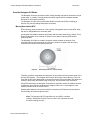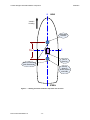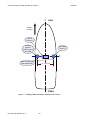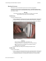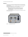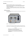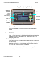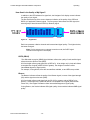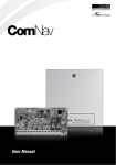
1
Navigator G4/G4B
GPS Compasses
Installation & Operation Manual
PN 29010082
ComNav Navigator G4/G4B Installation & Operation
Welcome
Welcome
Congratulations on your purchase of ComNav Marine’s Navigator G4/G4B GPS Compasses!
At ComNav, we are proud of our prominence as a leader in the design and manufacture of
marine autopilot systems. Our dedication to performance and reliability will ensure your
satisfaction with the Navigator G4/G4B.
ComNav Marine Ltd.
Warranty Notice
Prior to the installation and/or operation of the equipment, ensure that you read, understand,
and accept the conditions of the warranties as detailed in the Warranty Information section
of this manual.
Operator’s Warning
The P Series Autopilot System (with or without the Navigator G4/G4B) will steer your vessel.
However, it is only an aid to navigation. Its performance can be affected by many factors
including equipment failure, environmental conditions, and improper handling or use. An
autopilot system does not reduce your responsibility for the control of the vessel when
underway. You must always be in a position to monitor the course, supervise the autopilot,
and resume manual control if the need to do so arises.
Whenever underway, your vessel must be under the control of a qualified and alert person.
General Notice
This document, ComNav part number 29010082 Version 1 Revision 0, is the approved
Installation and Operation Manual for use with Navigator G4/G4B GPS Compasses. Where
versions of this manual exist in other languages, the English version shall be considered
authoritative.
Document PN 29010082 V1.0
-1-
ComNav Navigator G4/G4B Installation & Operation
Welcome
Document History
Revision
1R0
Date
29 February 2008
Document PN 29010082 V1.0
By
HG staff,
CN staff
-2-
Description
First Release (based on HG’s VS1x0 UG Rev B1)
ComNav Navigator G4/G4B Installation & Operation
Welcome
About this Manual
This manual provides essential information for the safe and reliable operation of your
ComNav Navigator G4/G4B GPS Compasses. You are urged to read this manual in its
entirety before you use your Navigator G4/G4B for the first time, and to keep it handy until
you become thoroughly familiar with the operation of the compass.
Manual Format
This manual has been formatted to be printed on both sides of the pages of the manual, and
on standard Letter-sized paper (8.5” x 11”). If you have obtained this manual as a soft-copy,
please note that it is in Adobe® Portable Document Format (“pdf”), and so may be viewed &
printed with Adobe Reader®, or compatible pdf-format viewers.
When printing this manual with Reader, you should select “duplex printing” (or the equivalent
term used by your printer’s software driver), in order to print it double-sided on the paper. If
your printer does not have built-in duplexing capability, you can still print this manual doublesided by following the instructions that came with your printer for doing “hand duplexing”.
You should also select the Auto-Rotate and Centre option in the Print Dialog box, de-select
the Choose Paper Source by PDF page size option, and set the Page Scaling to None.
Document PN 29010082 V1.0
-3-
ComNav Navigator G4/G4B Installation & Operation
Document PN 29010082 V1.0
-4-
ComNav Navigator G4/G4B Installation & Operation
Table of Contents
Table of Contents
Welcome....................................................................................................................................................... 1
Document History ....................................................................................................................................... 2
About this Manual____________________________________________________________________________ 3
Manual Format ____________________________________________________________________________ 3
Table of Contents........................................................................................................................................ 5
List of Figures ............................................................................................................................................. 7
List of Tables ............................................................................................................................................... 7
About the Navigator G4/G4B GPS Compasses...................................................................................... 11
GPS Overview _____________________________________________________________________________ 13
GPS Operation ___________________________________________________________________________ 13
Differential Operation ______________________________________________________________________ 14
Satellite Signal Loss? No Problem. ___________________________________________________________ 14
How the Navigator G4 Works__________________________________________________________________ 15
Moving Base Station RTK __________________________________________________________________ 15
Supplemental Sensors _____________________________________________________________________ 16
Time Constants __________________________________________________________________________ 18
Unpacking .................................................................................................................................................. 21
Parts List _________________________________________________________________________________ 22
Installation ................................................................................................................................................. 25
Technical Requirements______________________________________________________________________ 25
Caution _________________________________________________________________________________ 25
Power Supply ____________________________________________________________________________ 25
Tools___________________________________________________________________________________ 25
Mounting the Antennas ______________________________________________________________________ 26
Selecting the Antenna Orientation ____________________________________________________________ 26
Planning the Optimal Antenna Placement ______________________________________________________ 26
Mounting the Antennas ____________________________________________________________________ 29
Routing and Securing the Antenna Cable ________________________________________________________ 30
Mounting the Receiver _______________________________________________________________________ 31
Selecting the Receiver Orientation____________________________________________________________ 31
Mounting the Receiver _____________________________________________________________________ 31
Connecting the Cables _____________________________________________________________________ 33
Connecting the Power Source _______________________________________________________________ 33
Selecting a Port for GPS Data Sentence Output _________________________________________________ 33
Document PN 29010082 V1.0
-5-
ComNav Navigator G4/G4B Installation & Operation
Table of Contents
Setting Up...................................................................................................................................................37
Setting Basic Options with the Configuration Wizard _______________________________________________ 38
Operating....................................................................................................................................................43
Initializing the System _______________________________________________________________________
Viewing GPS/DGPS Status ___________________________________________________________________
Do I Have a Signal?_______________________________________________________________________
How Good is the Quality of My Signal?________________________________________________________
Troubleshooting a Signal Loss ________________________________________________________________
General Troubleshooting Checklist (GPS, DGPS, and Beacon)_____________________________________
Beacon ________________________________________________________________________________
External RTCM __________________________________________________________________________
Troubleshooting Heading ____________________________________________________________________
43
44
44
45
46
46
46
46
46
Customizing Settings ................................................................................................................................49
Disabling the Tilt Aid ________________________________________________________________________ 49
Disabling the Gyro Aid_______________________________________________________________________ 49
Configuring the Time Constants _______________________________________________________________ 50
Care & Maintenance ..................................................................................................................................53
Cleaning and Appearance ____________________________________________________________________
Protection of Wires and Cabling _______________________________________________________________
Periodic Checks____________________________________________________________________________
Fuse Replacement _________________________________________________________________________
53
53
53
54
Appendix 1: Frequently Asked Questions ..............................................................................................57
Appendix 2: Menus....................................................................................................................................59
Vector Menu ______________________________________________________________________________
GPS Menu ________________________________________________________________________________
Differential Menu ___________________________________________________________________________
SBAS __________________________________________________________________________________
Beacon ________________________________________________________________________________
External RTCM __________________________________________________________________________
Autonomous ____________________________________________________________________________
Configuration Wizard Menu ___________________________________________________________________
System Setup Menu ________________________________________________________________________
59
60
61
61
62
62
63
64
64
Appendix 3: Specifications.......................................................................................................................65
Receiver Specifications ______________________________________________________________________ 65
G4 (MA10) GPS Antenna Specifications_________________________________________________________ 67
G4B (MA40) DGPS Antenna Specifications ______________________________________________________ 68
Warranty Information ................................................................................................................................69
Index ...........................................................................................................................................................75
User Notes..................................................................................................................................................79
Document PN 29010082 V1.0
-6-
ComNav Navigator G4/G4B Installation & Operation
Table of Contents
List of Figures
Figure 1 – Navigator G4 GPS Compass ...........................................................................................................................12
Figure 2 – Secondary antenna’s search volume ...............................................................................................................15
Figure 3 – Navigator G4’s tilt aiding ..................................................................................................................................16
Figure 4 – Navigator G4’s gyro aiding...............................................................................................................................17
Figure 5 – Navigator G4 System Parts..............................................................................................................................21
Figure 6 – Heading and Pitch installation: top-down view of vessel ..................................................................................27
Figure 7 – Heading and Roll installation: top-down view of vessel....................................................................................28
Figure 8 – Pole Mounting ..................................................................................................................................................29
Figure 9 – Bracket Nuts ....................................................................................................................................................31
Figure 10 – Receiver Fastened to Bracket ........................................................................................................................31
Figure 11 – Mounting Receiver .........................................................................................................................................32
Figure 12 – Port connections on the Navigator G4 ...........................................................................................................33
Figure 13 – Port A/B Connectors (viewed from rear of G4)...............................................................................................34
Figure 14 – The Navigator G4’s Rear Panel .....................................................................................................................37
Figure 15 – Configuration Wizard Menu Tree ...................................................................................................................38
Figure 16 – The Navigator G4’s Rear Panel .....................................................................................................................43
Figure 17 – Navigator G4 Front Panel ..............................................................................................................................44
Figure 18 – Signal Bars.....................................................................................................................................................45
Figure 19 – Vector Menu Chart .........................................................................................................................................59
Figure 20 – GPS Menu Chart............................................................................................................................................60
Figure 21 – SBAS Menu Chart..........................................................................................................................................61
Figure 22 – Beacon Menu Chart .......................................................................................................................................62
Figure 23 – External RTCM Menu Chart...........................................................................................................................62
Figure 24 – Autonomous Menu Chart ...............................................................................................................................63
Figure 25 – System Setup Menu Chart .............................................................................................................................64
List of Tables
Table 1 – Navigator G4 System Parts List ........................................................................................................................22
Table 2 – Cable Loss ........................................................................................................................................................30
Table 3 – Default Data Sentences by Port ........................................................................................................................34
Table 4 – Pin Connections for Ports A and B ....................................................................................................................34
Table 5 – Time Constants .................................................................................................................................................50
Table 6 – Fuse Replacement Guide..................................................................................................................................54
Table 7 – GPS Receiver ...................................................................................................................................................65
Table 8 – Beacon Receiver (G4B) ....................................................................................................................................65
Table 9 – Data Communications .......................................................................................................................................66
Table 10 – Environmental .................................................................................................................................................66
Table 11 – Power Supply ..................................................................................................................................................66
Table 12 – Mechanical ......................................................................................................................................................66
Table 13 – GPS Antenna ..................................................................................................................................................67
Table 14 – Power Supply ..................................................................................................................................................67
Table 15 – Mechanical ......................................................................................................................................................67
Table 16 – GPS Antenna ..................................................................................................................................................68
Table 17 – Power Supply ..................................................................................................................................................68
Table 18 – Mechanical ......................................................................................................................................................68
Table 19 – User Notes .......................................................................................................................................................79
Document PN 29010082 V1.0
-7-
ComNav Navigator G4/G4B Installation & Operation
Document PN 29010082 V1.0
-8-
ComNav Navigator G4/G4B Installation & Operation
Introduction
Document PN 29010082 V1.0
-9-
ComNav Navigator G4/G4B Installation & Operation
Document PN 29010082 V1.0
- 10 -
ComNav Navigator G4/G4B Installation & Operation
Introduction
About the Navigator G4/G4B GPS Compasses
The Navigator G4 & G4B GPS Compasses offer a high-precision GPS heading solution to
meet the unique needs of the marine and machine control market.
The two models available – Navigator G4 and Navigator G4 B – are identical, except in their
Differential GPS (DGPS) correction features:
•
•
The Navigator G4 can obtain DGPS information from Space-Based Augmentation
System (SBAS) sources (where available & operational), including WAAS, EGNOS,
MSAS, SNAS and others. The G4 can also accept DGPS information from an external
data source.
The Navigator G4 can also utilize conventional terrestrial DGPS Radiobeacon signals to
obtain DGPS information, in addition to SBAS information & external DGPS data
sources.
The G4 has a receiver module that contains a Hemisphere GPS® Crescent® GPS/SBAS
receiver, with a single axis gyro & a tilt sensor. It is supplied with two separate GPS antenna
modules.
The Navigator G4B receiver module also contains a Hemisphere SBX-4 DGPS Radiobeacon
receiver module, and one of the G4B’s antenna modules also contains an H-field beacon
signals antenna.
The G4 can achieve heading accuracy ranging from 0.1 to 0.6 degrees (rms), depending on
the antennae separation. In addition, it offers a GPS positioning performance of less than
1 metre (rms), using WAAS or other suitable differential GPS signals.
While the Navigator G4s are designed to provide a highly-accurate GPS heading, taking into
account the pitch, roll and speed of various marine vessels, the use of the Navigator G4 is
not limited to the marine market. Other excellent applications include machine control and
agricultural guidance, or any application that requires a high precision heading solution.
Note: most of the information in this manual applies to both the
Navigator G4 and the Navigator G4B GPS Compasses.
For easier reading, most references in the text use the term “G4” – but
that should always be understood as referring to both models.
Whenever a particular item applies only to the G4B, it will be so stated in
the text of that item.
When using this manual with the Navigator G4 model, please ignore the
sections which discuss Radiobeacon signals, beacon receiver operation
and installation details which relate to the beacon signals & receiver.
Document PN 29010082 V1.0
- 11 -
ComNav Navigator G4/G4B Installation & Operation
Introduction
Figure 1 – Navigator G4 GPS Compass
The receiver module features the exclusive Hemisphere GPS, Crescent-branded,
application-specific integrated circuit (ASIC) computer chipset technology that enables it to
achieve:
•
•
•
•
•
•
•
higher update rates
noise-reduced raw measurements
more memory
more processor capacity
lower power consumption
more advanced applications and sophisticated configurations
tighter coupling of measurements from separate antennae
The Navigator G4 offers excellent accuracy and stability due to more accurate code phase
measurements, improved multipath mitigation and fewer components than competing
products.
Note: the Navigator G4/G4B GPS Compasses are customised OEM
versions of the VS100/110 GPS Compasses made by Hemisphere
GPS™ (formerly CSI Wireless), of Calgary, Alberta, Canada and
Scottsdale, Arizona, U.S.A.
The ComNav GPS Compasses have slight differences from the
corresponding Hemisphere models, in their operational specifications; for
details, please refer to the respective ComNav & Hemisphere models’
specifications.
The Navigator G4/G4B do not support any of Hemisphere’s various
optional GPS/DGPS receiver features or subscription applications (e-Dif,
OmniStar, L-Dif™, etc.).
Document PN 29010082 V1.0
- 12 -
ComNav Navigator G4/G4B Installation & Operation
Introduction
GPS Overview
For your convenience, the Navigator G4 automatically tracks and calculates position
information with complex algorithms, whether using GPS or differential GPS (DGPS).
When turned on for the first time, the Crescent system acquires the available GPS satellites
in view and the satellite-based augmentation system (SBAS) differential service.
If SBAS is not available in your area, you can use Beacon corrections, depending on your
model. Alternatively, you may use an external source of RTCM SC-104 differential
corrections.
GPS Operation
The GPS engine is always operating, regardless of the DGPS mode of operation. The
following sections describe the general operation of the Navigator G4’s internal GPS engine.
Automatic Tracking
The Navigator G4’s internal GPS engine automatically searches for GPS satellites, acquires
the signals and manages the navigation information required for positioning and tracking.
This is a hands-free mode of operation.
Receiver Performance
The Navigator G4 works by finding 4 or more GPS satellites in the visible sky and uses the
information those satellites provide to compute an appropriate position (within 2.5 metres).
Since there is some error in the GPS data calculations, the Navigator G4 also tracks a
differential correction. The Navigator G4 uses the differential corrections to improve its
position to less than 1 metre.
There are two main aspects of GPS receiver performance:
•
•
positioning
satellite acquisition quality
When the Navigator G4 is properly positioned, the satellites transmit coded information to the
antenna on a specific frequency that allows the receiver to calculate a range to each satellite.
GPS is essentially a timing system. The ranges are calculated by timing how long it takes for
the GPS signal to reach the GPS antenna. To calculate the geographic location, the GPS
receiver uses a complex algorithm incorporating satellite locations and ranges to each
satellite. Reception of any 4 or more of these signals allows a GPS receiver to compute
3-dimensional coordinates.
Document PN 29010082 V1.0
- 13 -
ComNav Navigator G4/G4B Installation & Operation
Introduction
Differential Operation
The purpose of differential GPS (DGPS) is to remove the effects of atmospheric errors, timing
errors and satellite orbit errors, while enhancing system integrity.
Autonomous positioning capabilities of the Navigator G4 will result in positioning accuracies
of 2.5 m (rms). In order to improve positioning quality to sub-metre levels, the Navigator G4
uses differential corrections received through one of the following:
•
•
the internal SBAS demodulator
Radiobeacon corrections
For more information on available differential services and the associated commands, please
refer to the Hemisphere GPS Technical Reference manual (supplied with the G4, or on
Hemisphere’s web site).
Automatic SBAS (WAAS, EGNOS, MSAS, etc.) tracking
The Navigator G4 will automatically scan and track SBAS signals without the need to tune
the receiver. The Navigator G4 features two-channel tracking that provides an enhanced
ability to maintain a lock on a SBAS satellite when more than one satellite is in view. This
redundant tracking approach results in more consistent tracking of a SBAS signal when in an
area where signal blockage of a satellite is possible.
Beacon Operation
Many marine authorities, such as coast guards, have installed networks of Radiobeacons that
broadcast DGPS corrections. Increasingly, this Radiobeacon network is used for terrestrial
applications as well, resulting in a densification of networks inland. The dual-channel beacon
receiver in the G4B is able to operate in manual or automatic tuning mode. Alternately, a
database mode will select the closest station in compliance with IEC 61108-4 standards.
Satellite Signal Loss? No Problem.
The exclusive Hemisphere GPS COAST™ software enables the Navigator G4 receivers to
use old DGPS correction data for 40 minutes or more without significantly affecting the quality
of positioning.
Document PN 29010082 V1.0
- 14 -
ComNav Navigator G4/G4B Installation & Operation
Introduction
How the Navigator G4 Works
The Navigator G4 series provides accurate, reliable heading and position information at high
update rates. It consists of a high performance GPS engine and two multipath-resistant
antennas for GPS signal processing.
The Navigator G4 uses moving base station Real-Time Kinematic (RTK) technology to
achieve very precise heading and position accuracies.
Moving Base Station RTK
RTK technology uses two antennas. One antenna is designated as the primary GPS, while
the other is designated as the secondary GPS.
Knowing the fixed distance between the primary and secondary antennas (by default, 0.5 m)
allows the Navigator G4 to constrain its search volume when computing GPS satellite
positioning data.
The Navigator G4 is able to constrain its search volume because the location of the
secondary antenna can theoretically only fall on the surface of a sphere with the radius
centered on the location of the primary antenna:
Figure 2 – Secondary antenna’s search volume
Therefore, positions computed by the Navigator G4 are referenced to the phase center of the
primary GPS antenna. The Navigator G4’s internal GPS engine uses both the L1 GPS C/A
code and the RF carrier phase data to compute the location of the secondary GPS antenna in
relation to the primary GPS antenna with a very high, sub-centimetre level of precision.
Using RTK technology, the Navigator G4 analyzes a significant number of possible solutions
to determine where various combinations of integer numbers of L1 wavelengths to each
satellite intersect within the search volume.
Heading data references the vector formed from the primary GPS antenna phase center to
the secondary GPS antenna phase center.
Note: The Navigator G4 RTK algorithm only uses GPS to calculate
heading. Differential corrections are not used in this calculation and will
not affect heading accuracy.
Document PN 29010082 V1.0
- 15 -
ComNav Navigator G4/G4B Installation & Operation
Introduction
Supplemental Sensors
The Navigator G4 contains an integrated tilt sensor and gyro, which are enabled by default.
Each supplemental sensor may be turned on or off individually; however, the full functionality
of the Navigator G4 system is realized only when both are used. Each supplemental sensor
is inside the Navigator G4 enclosure, mounted on the internal printed circuit board.
Both sensors act to reduce the RTK search volume, which improves heading startup and
reacquisition times. This also improves heading reliability and accuracy by eliminating other
possible erroneous solutions.
The GPS Technical Reference manual describes the commands and methodology required
to recalibrate, query or change the status of these sensors.
Tilt aiding
The Navigator G4’s internal tilt sensor (accelerometer) is enabled by default and is factory
calibrated. The tilt sensor constrains the RTK heading solution beyond the volume
associated with just a fixed antenna separation. It is able to do so since the Navigator G4
knows the approximate inclination of the secondary antenna with respect to the primary
antenna.
The search space defined by the tilt sensor is reduced to a horizontal ring on the surface of
the sphere. By reducing the search volume, startup and reacquisition times are considerably
decreased (see Figure 3).
Figure 3 – Navigator G4’s tilt aiding
Document PN 29010082 V1.0
- 16 -
ComNav Navigator G4/G4B Installation & Operation
Introduction
Gyro aiding
The gyro initializes and calibrates itself when power is turned on. Alternately, you can
manually calibrate it as outlined in the GPS Technical Reference manual. When the gyro is
first initializing, the dynamics the gyro experiences MUST BE SIMILAR to the regular
operating dynamics.
For example, if you will be using the Navigator G4 on a high-speed, manoeuvrable craft, you
must use the receiver under highly dynamic conditions for the first 5 to 10 minutes after
turning on power, rather than sitting stationary.
Figure 4 – Navigator G4’s gyro aiding
The Navigator G4’s internal gyro offers two benefits.
1. It shortens reacquisition times when a GPS heading is lost due to obstruction of
satellite signals. The gyro reduces the search volume required for solution of the
RTK by providing a relative change in angle since the last computed heading.
When used in conjunction with the tilt sensor, the search space is reduced to a
wedge-shaped range (see Figure 4).
2. It also provides an accurate substitute heading for a short period (depending on the
roll and pitch of the vessel), ideally seeing the system through to reacquisition. The
gyro will provide an alternate heading source accurate to within 1° for up to
3 minutes if either antenna loses GPS.
If the outage lasts longer than 3 minutes, the Navigator G4 will assume the gyro readings
have drifted too far and it will begin outputting null fields in the heading output sentences.
This 3-minute time-out period is fixed and cannot be changed.
Document PN 29010082 V1.0
- 17 -
ComNav Navigator G4/G4B Installation & Operation
Introduction
Time Constants
The Navigator G4 incorporates customizable time constants that can provide a degree of
smoothing to the heading, course-over-ground and speed measurements.
Depending on the expected dynamics of the vessel, you may wish to adjust these
parameters. For instance, if the vessel is very large and is not able to turn or pitch quickly,
increasing this time is reasonable. The resulting values would have reduced “noise”,
resulting in consistent values with time. However, artificially increasing this value such that it
does not agree with a more dynamic vessel could create a lag in measurements. Formulas
for determining the level of smoothing are located in Configuring the Time Constants (see
page 50). If you are unsure on how to set this value, it is best to be conservative and leave it
at the default setting.
Heading
The heading time constant allows you to adjust the level of responsiveness of the true
heading measurement provided in the $HEHDT (& the alternate $GPHDT) sentence. The
default value of this constant is 2.0 seconds of smoothing when the gyro is enabled. The
gyro is enabled by default, but can be turned off. If you turn off the gyro, the equivalent
default value of the heading time constant is 0.5 seconds of smoothing. However, if you turn
off the gyro, you will need to enter this heading constant manually. Increasing the time
constant will increase the level of heading smoothing.
Pitch
The pitch time constant allows you to adjust the level of responsiveness of the pitch
measurement provided in the $PSAT,HPR sentence. The default value of this constant is
0.5 seconds of smoothing. Increasing the time constant will increase the level of pitch
smoothing.
Heading rate
The heading rate time constant allows you to adjust the responsiveness level of the rate of
heading change measurement provided in the $HEROT sentence. The default value of this
constant is 2.0 seconds of smoothing. Increasing the time constant will increase the level of
heading smoothing.
Course-over-ground (COG)
The course-over-ground (COG) time constant allows you to adjust the level of
responsiveness of the COG measurement provided in the $GPVTG sentence. The default
value of this constant is 0.0 seconds of smoothing. Increasing the time constant will increase
the level of COG smoothing. COG is computed using the primary GPS engine only, and its
accuracy is dependant upon the speed of the vessel (noise is proportional to 1/speed). When
stationary, this value is invalid.
Speed
The speed time constant allows you to adjust the level of responsiveness of the speed
measurement provided in the $GPVTG sentence. The default value of this parameter is
0.0 seconds of smoothing. Increasing the time constant will increase the level of speed
measurement smoothing.
Document PN 29010082 V1.0
- 18 -
ComNav Navigator G4/G4B Installation & Operation
Unpacking
Document PN 29010082 V1.0
- 19 -
ComNav Navigator G4/G4B Installation & Operation
Document PN 29010082 V1.0
- 20 -
ComNav Navigator G4/G4B Installation & Operation
Unpacking
Unpacking
Please look over the parts shipped with your system. If anything is damaged due to shipping,
please contact your freight carrier. If any parts are missing, please contact your dealer.
Figure 5 – Navigator G4 System Parts
Document PN 29010082 V1.0
- 21 -
ComNav Navigator G4/G4B Installation & Operation
Unpacking
Parts List
Diagram Letter
A
Part Name
Navigator receiver:
either:
- G4
- G4B
Qty
Part Number
1
30130008
30130011
1
30120001
B
Receiver mounting bracket
(2 brackets, with fasteners)
C
G4:
- G4 (MA10) GPS antenna
2
30130009
G4B:
- G4 (MA10) GPS antenna
- G4B (MA40) DGPS antenna
1
1
30130009
30130010
D
Antenna cable (TNC – TNC), 3 metres
2
31110045
E
Data cable (DE9 – DE9), 3 metres
2
31110044
F
Power cable, 3 metres
1
31110046
Manuals:
Navigator G4/G4B Installation & Operation
GPS Technical Reference*
PocketMAX User Manual*
1
1
1
29010082 v1r0
875-0175-000 Rev C1
875-0178-000 Rev A1
Not pictured
* these two manuals are by Hemisphere GPS & their part numbers are Hemisphere’s
Table 1 – Navigator G4 System Parts List
Document PN 29010082 V1.0
- 22 -
ComNav Navigator G4/G4B Installation & Operation
Installation
Document PN 29010082 V1.0
- 23 -
ComNav Navigator G4/G4B Installation & Operation
Document PN 29010082 V1.0
- 24 -
ComNav Navigator G4/G4B Installation & Operation
Installation
Installation
Technical Requirements
The following are the basic technical requirements that should be met before
installation of the Navigator G4/G4B on your vessel.
Caution
Please refer to the Warranty Information in the Warranty section of this
manual before proceeding with installation of the Navigator G4/G4B.
Hazard warning!
CAUTION!
Extreme caution is advised when using tools powered by alternating
current (AC) from main AC supply circuits, regardless of whether the
supply circuits are “indoor”, “outdoor”, “marine” or “industrial” rated.
Water, especially sea water, is an EXCELLENT conductor of electricity,
and can complete a path to AC Ground through a person’s body,
causing injury or death, if a tool malfunctions or short-circuits.
⇒ Battery powered tools are STRONGLY recommended ⇐
If AC tools are used, they MUST be plugged into a circuit that is
adequately protected against Ground Faults and other safety hazards,
in accordance with local electrical codes.
Power Supply
For safe & reliable operation of your Navigator G4/G4B, your vessel’s power supply system
must have an adequately-breakered, or fused, DC (direct current) power supply at a nominal
voltage between 9 and 36 volts. Ensure that adequate wire sizes are used to handle the
expected maximum currents.
Tools
General-purpose tools such as a portable drill, pliers, wire cutters, screwdrivers, wire,
mounting bolts and wrenches will be required.
Document PN 29010082 V1.0
- 25 -
ComNav Navigator G4/G4B Installation & Operation
Installation
Mounting the Antennas
Selecting the Antenna Orientation
The Navigator G4 series GPS compass can be installed:
•
•
to read heading and pitch, or
heading and roll.
The relation of the antennas to the boat’s axis determines whether the Navigator G4 will
output pitch or roll readings in addition to heading.
Pitch
Installing for heading and pitch is the most common installation. Orienting the antennas
parallel to, and along the centreline of, the axis of the boat will provide a true heading.
You can enter a heading bias in the Navigator G4 to calibrate the physical heading to the true
heading of the boat, if you have some a gyrocompass.
Roll
Installing for heading and roll is an alternate installation. Orienting the antennas
perpendicular to, and along the centreline of, the axis of the boat will provide roll readings.
Note: If you choose this installation, you will need to enter a heading
bias in the Navigator G4. The heading bias will be either +90° if the
antennas face to Port, or -90° if the antennas face to Starboard.
Planning the Optimal Antenna Placement
Optimal antenna placement is important to obtain a high-precision GPS reading. Antennas
must be placed:
•
•
•
with a clear view of the horizon
away from other electronics and antennas
along the fore-aft &/or athwartships centrelines of the vessel
Warning!
The Navigator G4 will not translate its position to the vessel’s
centreline if not installed along the centreline.
•
•
•
•
•
•
on a level plane
at a maximum separation of 2.0 m (default is 0.5 m)
away from radio frequencies and as high as possible
with the connectors on both antenna modules pointing the same direction
with the primary antenna located somewhere in front of the front panel of the receiver
module, but still along the vessel’s centreline
with the secondary antenna located behind the back panel of the receiver module,
but still along the vessel’s centreline
Note: Both antennae supplied with the G4 are identical, thus either
may be used as the primary antenna. For the G4B, the DGPS
(labelled “G4B” or MA40) antenna must be the primary antenna.
See Figure 6 and Figure 7 for examples.
Document PN 29010082 V1.0
- 26 -
ComNav Navigator G4/G4B Installation & Operation
Installation
CL
BOW
Vessel’s
Heading
Secondary
Antenna
0.5 – 2
metres
CL
Face of
Receiver
Both Connectors
Point Sternwards
Primary
Antenna
(DGPS module
with G4B)
STERN
Figure 6 – Heading and Pitch installation: top-down view of vessel
Document PN 29010082 V1.0
- 27 -
ComNav Navigator G4/G4B Installation & Operation
Installation
CL
BOW
Vessel’s
Heading
Face of
Receiver
Primary
Antenna
(DGPS module
with G4B)
Secondary
Antenna
CL
Both Connectors
Point Sternwards
0.5 – 2 metres
STERN
Figure 7 – Heading and Roll installation: top-down view of vessel
Document PN 29010082 V1.0
- 28 -
ComNav Navigator G4/G4B Installation & Operation
Installation
Mounting the Antennas
The antennas may be mounted with a pole mount or rail mount configuration.
The antennas are secured to the mounting bracket using 1-14-UNS-2B threaded mounts.
The antenna module’s mount is located beneath the mass centre of the antennas in order to
resist vibration modes.
Warning!
The maximum allowable antenna separation is 2.0 metres. Any increase
beyond this limit may result in an incorrect heading.
Pole Mounting
To mount an antenna on a pole:
1. Select a location and orientation that meets the requirements listed in “Selecting the
Antenna Orientation” and “Planning the Optimal Antenna Placement” on page 26.
2. Thread the mounting pole into the mounting bracket on the bottom of the antenna.
Figure 8 – Pole Mounting
Warning!
When threading the pole mounts, hand-tighten only.
Damage resulting from over-tightening is not covered by warranty.
Note: The pole shown in the photos is not included; it must be
supplied by you or your Dealer.
3. Mark and drill any mounting holes necessary for the pole mounts.
Rail Mounting
To rail mount an antenna:
1. Select a location and orientation that meets the requirements listed in “Selecting the
Antenna Orientation” and “Planning the Optimal Antenna Placement” on page 26.
2. Use appropriate hardware to securely attach the antenna to the chosen railing.
Document PN 29010082 V1.0
- 29 -
ComNav Navigator G4/G4B Installation & Operation
Installation
Routing and Securing the Antenna Cable
To route and secure the antenna cables, please review the following guidelines.
•
•
•
•
The two enclosed antennas each require a 50 Ω impedance antenna extension cable
such as RG-58U (up to a maximum of 15 metres [49 ft.] in length) for proper
operation.
The GPS engine inside the Navigator G4 requires a minimum input gain of 10 dB
(and maximum of 40 dB before saturation will occur). The antennas offer 28 dB of
gain, so the loss budget to accommodate for cable losses is 18 dB.
Regardless of the cable material and length that you choose, you must ensure that
cable losses are less than 18 dB of attenuation. Due to variances in the antenna
gain and practical attenuation of cable materials and connectors, we recommend
reducing this budget to 15 dB. This budget of 15 dB is present to overcome the
resulting attenuation of an RF cable.
When deciding on an antenna location, consider the amount of cable required. Keep
in mind that a longer cable of the same material will result in a higher loss than a
shorter one. If the overall loss of the longer cable exceeds 15 dB, the cable material
will need to be changed. This normally means a more expensive material that has a
larger diameter and less flexibility. The standard cables that come with the Navigator
G4 are of an RG58 material family. Their attenuation is approximately 0.8 dB/metre.
Including connector losses, the nominal loss of these RF cables is approximately
10 dB, which is within the tolerable loss budget. If a 15 or 20 metre cable run is
required, an RG8 variety is available. If lengths longer than 20 metres are required,
more sophisticated materials will be required.
For more information on cable length or low-loss cable, please contact your ComNav Marine
dealer. The following is a short summary of other readily available cable materials that have
50 Ω impedance. Cable loss cited below does not include any connector losses.
Material
Loss at GPS L1 (1.575 GHz)
RG58
0.78 dB/m
RG8
0.36 dB/m
Times Microwave LMR400
0.15 dB/m
Table 2 – Cable Loss
Warning!
When choosing a route for the antenna extension cable:
•
•
•
•
•
•
•
•
Document PN 29010082 V1.0
Avoid running cables in areas of excessive heat.
Keep antenna cables away from corrosive chemicals.
Do not run the extension cable through door or window jams.
Keep the antenna cable away from rotating machinery.
Improperly installed cables near machinery can be dangerous.
Do not bend excessively or crimp the antenna extension cable.
Avoid placing tension on the cable.
Remove unwanted slack from the antenna extension cable at the receiver end.
Secure along the cable route using plastic tie wraps.
- 30 -
ComNav Navigator G4/G4B Installation & Operation
Installation
Mounting the Receiver
Selecting the Receiver Orientation
The Navigator G4 must be installed:
• inside and away from the elements, and in a location that minimizes vibration, shock,
extreme temperatures and moisture
• horizontally
• with the front panel of the receiver facing the primary antenna
• so the front panel (menu screen, LEDs and buttons) is visible and accessible
• so the back panel is visible and accessible to switch out cables and turn power on and off
Mounting the Receiver
Use the enclosed mounting kit to mount the receiver. To install the brackets for mounting:
1. Slide the nuts through the opening along both sides of the receiver.
Figure 9 – Bracket Nuts
2. Place the bracket alongside the receiver and insert the thumb screws so they screw
into the nuts.
Figure 10 – Receiver Fastened to Bracket
Document PN 29010082 V1.0
- 31 -
ComNav Navigator G4/G4B Installation & Operation
Installation
3. Screw down the brackets in your desired location, using fasteners (not supplied)
which suit the location & surface.
Figure 11 – Mounting Receiver
Document PN 29010082 V1.0
- 32 -
ComNav Navigator G4/G4B Installation & Operation
Installation
Connecting the Cables
This section contains instructions for connecting the cables for:
•
•
power
serial ports
Warning!
The Navigator G4 receiver provides 5 VDC across the antenna ports.
Connection to incompatible devices may result in damage to equipment.
Connecting the Power Source
The power source for the Navigator G4 must be between 10 - 36 Volts DC.
Use the Power cable (PN 31110046) to connect the connector labelled “Power Ground” to
your power source.
Selecting a Port for GPS Data Sentence Output
The serial ports of the Navigator G4 operate at the RS-232C interface level, to communicate
with autopilot systems, external data loggers, navigation systems and other devices.
Note: most marine equipment fully conforming to the NMEA 0183 standard
uses the RS-422 electrical interface standard. In order to connect the
Navigator G4 to such equipment, an external RS-232C/RS-422 convertor
is required. Contact your ComNav Dealer if you need a convertor.
There are two serial ports available on the back panel of the Navigator G4, each using a
standard DE9 socket connection.
Figure 12 – Port connections on the Navigator G4
Document PN 29010082 V1.0
- 33 -
ComNav Navigator G4/G4B Installation & Operation
Installation
The available ports and associated default baud rates, NMEA sentence types and update
rates are shown in Table 3.
Port
Baud Rate
NMEA Sentences
Update Rate
A, B
19,200
GGA, GSV
1 Hz
Table 3 – Default Data Sentences by Port
Ports A and B have the connections detailed below on the DE9 socket.
Pin
Signal
Description
2
TXD
NMEA 0183, binary, and RTCM output
3
RXD
NMEA 0183, binary, and RTCM input
5
Signal Ground
Signal return
6
Mark Input
Event marker input
9
1 PPS
Timing output
Table 4 – Pin Connections for Ports A and B
Figure 13 – Port A/B Connectors (viewed from rear of G4)
After selecting the physical connection, you will need to select the desired NMEA data
sentences, if different from the defaults shown above.
Select the desired NMEA sentence types and update rates by port using the Configuration
Wizard (see Setting Basic Options on page 38).
Document PN 29010082 V1.0
- 34 -
ComNav Navigator G4/G4B Installation & Operation
Setting Up
Document PN 29010082 V1.0
- 35 -
ComNav Navigator G4/G4B Installation & Operation
Document PN 29010082 V1.0
- 36 -
ComNav Navigator G4/G4B Installation & Operation
Setting Up
These instructions are for configuring the Navigator G4 settings using the display & keypad
on the Navigator G4 receiver module. A Configuration Wizard in the receiver itself walks you
through setup options.
The Configuration Wizard allows you to save up to five different configuration settings, if
using this product on different vessels, or for different applications.
Note: If using a personal computer, you may also use Hemisphere GPS’
PocketMAXPC software tool 1 , which can be obtained from Hemisphere’s
web site. Please refer to the PocketMAX User Manual supplied with the
G4, for help on using it.
First, use the ON/OFF POWER switch on the rear panel to turn on the G4 (push in the switch
for On, push it again for Off).
Figure 14 – The Navigator G4’s Rear Panel
1
There is also a version of PocketMAX that can be used on a Pocket PC.
Document PN 29010082 V1.0
- 37 -
ComNav Navigator G4/G4B Installation & Operation
Setting Basic Options with the Configuration Wizard
The Configuration Wizard is one of the choices on the Main Menu in the display on the front
panel of the Navigator G4.
This section covers the basic items you need to set in the Configuration Wizard to get up and
running. Figure 15 shows a chart of the Configuration Wizard menu.
Note: basic setup assumes that you are using the following defaults:
•
•
antennas are installed parallel to, and along the centerline of, the boat’s axis
antennas are separated by 0.5 metres
If this is not the case, you will need to also enter the actual antenna
separation and bias in the Wizard.
Figure 15 – Configuration Wizard Menu Tree
Perform the following steps using the Configuration Wizard (see the path shown in red arrows
in Figure 15).
Document PN 29010082 V1.0
- 38 -
ComNav Navigator G4/G4B Installation & Operation
1. Start the Configuration Wizard
⇒ select the Config Wizard item from the main menu.
2. Select Proceed Wizard
In this submenu, you can also:
•
•
delete a previously saved configuration
use a previously saved configuration
3. Select Create New to create a New Configuration
You may alternately save the current receiver configuration, if you have modified the
receiver setup through other menu items or via the COM port.
4. Enter the Name of the Configuration
To enter a name to save your current setting under:
•
•
•
First, use the arrow keys to select a letter and then press the enter key to
save the letter. The cursor will move to the right.
Enter a blank character at the end of your name until the “Enter” character
appears at the end of the name.
When you are finished, press the enter key again.
After entering the configuration name, the first few letters of the name will be
displayed on the previous menu.
5. Select a DGPS Source
The default DGPS source is SBAS. If using a differential source other than SBAS,
please select it here.
Options are: SBAS, *Beacon, Autonomous, and External RTCM
*Beacon is only available on the G4B.
6. Select the GPS Data Sentence Outputs
Select each of the NMEA &/or proprietary sentence(s) that you want to be output on
each of the two Data Ports, and the update rate for each one to be output.
7. Configure the Elevation Cutoff Angle
You may set the Elevation Cutoff Angle between 0° and 45°. The default value is 5°.
8. Set the Maximum DGPS Age (Optional)
The maximum DGPS age is 3600 seconds (60 minutes) by default. If you need a
shorter or longer DGPS age, set it here.
9. Configure the Baud Rate (Optional)
If the default Baud rate on the desired port does not match that of the external device
you are connecting to, you will need to set it here.
Available values: 4800, 9600, 19200, 38400, 57600
Document PN 29010082 V1.0
- 39 -
ComNav Navigator G4/G4B Installation & Operation
10. Configure Aiding Features (Optional)
While the default settings will work for most users, you can configure the aiding
features to reduce heading startup and reacquisition times.
Customers who may want to configure aiding features include those with a large,
slow-to-turn vessel, or those with a small, dynamic vessel.
To configure the aiding features, see page 49.
11. Configure Time Constants (Optional)
While the default settings will work for most users, you can configure the time
constants to reduce heading start up and reacquisition times.
Customers who may want to configure aiding features include those with a large,
slow-to-turn vessel, or those with a small, dynamic vessel.
To configure the time constants, see page 50.
12. Input the Heading Bias (Optional)
If you installed the antennae exactly parallel to the vessel’s fore-aft centreline, the
Heading Bias is 0.0°.
If you did not install the antennae exactly parallel to and along the centreline, enter a
heading bias (-180.0° to +180.0°) to compensate for the angle of offset from the
centerline.
Note: If you installed the antennae for roll (i.e., perpendicular to the
vessel’s centreline), rather than pitch, the Heading Bias you enter will be
+90.0° or -90.0° (plus or minus any offset from a perpendicular to the
centreline).
You must also enter the bias for roll (see below).
13. Input the Bias for Pitch or Roll (Optional)
Enter the bias for pitch or roll (-15.0° to +15.0°) to compensate for any offset from the
vessel’s centreline (or from perpendicular to the centerline, if installed for Roll).
14. Select the Antenna Separation (Optional)
If you did not install the antennas 0.5 metres apart, enter the actual antenna
separation here.
Available range is 0 – 2.0 metres
15. Configure the Navigator G4 for Pitch or Roll
Pitch is the default installation for most users. If you installed the Navigator G4 to
read roll, select “Roll” here.
16. Save Your Settings
•
•
•
Document PN 29010082 V1.0
After selecting the “Save to Location” option at the end of the Configuration
menu, you will be prompted for a location to save your configuration.
Select one of the empty slots, noted by the name “Not Used”, or select a slot with
an existing configuration to overwrite it.
After saving your configuration, you must re-enter the Configuration Wizard and
select the configuration to use. In this way, you may continue to enter different
receiver configurations without upsetting the current operation of the receiver.
- 40 -
ComNav Navigator G4/G4B Installation & Operation
Operating
Document PN 29010082 V1.0
- 41 -
ComNav Navigator G4/G4B Installation & Operation
Document PN 29010082 V1.0
- 42 -
ComNav Navigator G4/G4B Installation & Operation
Operating
Operating
Operating the Navigator G4 is simple. Turn it on and you’re ready to go!
Most users connect the Navigator G4 to their existing navigation system during installation.
These users will receive the Navigator G4’s position and heading updates through the
interface of their existing system.
The interface on the front panel of the Navigator G4 is helpful for configuring or changing
system settings. In addition, the LEDs on the panel will notify you in the event of a GPS or
DGPS signal loss.
Initializing the System
Use the ON/OFF Power switch on the rear panel to turn on the G4 (push in the switch for On,
push it again for Off).
Figure 16 – The Navigator G4’s Rear Panel
The main menu screen (see Figure 17) appears in the display on the front panel each time
the G4 is turned on. See Setting Basic Options on page 38 for help configuring your system.
Warning!
When the gyro is first initializing, the dynamics the gyro experiences
MUST BE SIMILAR to the regular operating dynamics.
For example, if you will be using the Navigator G4 on a high speed,
manoeuvrable craft, you must use the receiver under highly dynamic
conditions for the first 5 to 10 minutes after turning on power, rather than
sitting stationary.
Document PN 29010082 V1.0
- 43 -
ComNav Navigator G4/G4B Installation & Operation
Operating
Display Screen (showing Main Menu)
Signal-lock
Indicators
Selection
Buttons
Heading
Up/Forward
Differential
(SBAS or Beacon)
Enter/Select
Secondary GPS
Primary GPS
Down/Back
Power-On
Indicator
Figure 17 – Navigator G4 Front Panel
For full information on all the menus, please see Appendix 2: Menu on page 59in the
Appendix.
Viewing GPS/DGPS Status
Most users will receive position and heading information through their on-board navigation
system. If you have not connected the Navigator G4 to an existing navigation system, or are
troubleshooting your unit, you may need to view GPS, DGPS or Beacon status on the
Navigator G4’s display screen.
Do I Have a Signal?
Figure 17 shows which LEDs on the Navigator G4 will indicate GPS, DGPS or Beacon signal
lock when illuminated.
If you do lose the differential signal lock, the Hemisphere GPS COAST technology allows the
Navigator G4 to perform well for up to 45 minutes with old correction data. The amount of
time you can “coast” depends on the degree of tolerable drift.
Note: In order to obtain a full set of SBAS corrections, the Navigator G4
must receive the ionospheric map over a period of a few minutes. After
this, the receiver can “coast” until the next set of corrections has been
received.
Document PN 29010082 V1.0
- 44 -
ComNav Navigator G4/G4B Installation & Operation
Operating
How Good is the Quality of My Signal?
In addition to the LED indicators for signal lock, the Navigator G4’s display screen indicates
the quality of your signal.
The bar chart at the top of the screen shows an indication of the quality of the GPS and
DGPS (or if applicable, Beacon) signal. The first group of bars shows the GPS signal; the
second group of bars shows the DGPS (or Beacon) signal.
Figure 18 – Signal Bars
Each bar represents a distinct channel and its associated signal quality. The higher the bar,
the better the signal.
Note: If using autonomous or external correction mode, the DGPS signal
indicator will not appear in the display.
DGPS (SBAS)
The differential correction (SBAS) signal indicator reflects the quality of each satellite signal,
referred to as the Bit Error Rate (BER).
A full bar height reflects good signal lock (a BER of 0). A bar height only 2 pixels tall reflects
a complete loss of signal (a BER of 500 or greater). Bar heights in between reflect
intermediate degrees of signal quality.
For example, if using WAAS, there are two satellites available, so two BERs are provided.
Beacon
The Beacon indicator reflects the quality of the Beacon signal, in terms of the signal strength
(SS) and the signal-to-noise ratio (SNR).
A full bar height reflects good signal lock (an SS of 35 or greater, and an SNR of 24 or
greater). A bar height only 2 pixels tall reflects a a complete loss of signal (SS and SNR
values of 0). Bar heights in between reflect intermediate degrees of signal quality.
If using Beacon, the first bar indicates SS signal quality; the second bar indicates SNR signal
quality.
Document PN 29010082 V1.0
- 45 -
ComNav Navigator G4/G4B Installation & Operation
Operating
Troubleshooting a Signal Loss
With the Hemisphere GPS COAST technology, you should be able to continue working in the
event of a GPS or DGPS signal loss.
General Troubleshooting Checklist (GPS, DGPS, and Beacon)
•
•
•
•
•
Check antenna connections.
Verify antennas have an unobstructed view of the sky.
Verify the lock status of the satellites.
Confirm baud rates match external source.
Verify the differential source.
Beacon
In addition to checking the above general items, check the following:
•
•
•
Verify that the receiver is tuned to the correct frequency and bit rate.
Verify antennas are away from potential sources of interference.
Ensure Beacon signal coverage is available in your area.
External RTCM
In addition to checking the above general items, check the following:
•
•
•
Verify the pin-out between the RTCM source and the RTCM input port (transmit from the
source must go to receive of the RTCM input port and grounds must be connected).
Verify that the baud rate of the RTCM input port matches the baud rate of the external
source.
Ensure corrections are being transmitted to the correct port.
Troubleshooting Heading
In the event of no heading or incorrect heading values, use the following checklist:
•
•
Verify that the primary antenna is located towards the stern, and the secondary antenna
towards the bow (Heading is from Primary to Secondary antenna).
Check the measurement of the antenna separation. The Measured (MSEP) and
Calculated (CSEP) values are in metres, and should agree to within 1 centimetre. CSEP
will continuously change, so you should average this reading over a few minutes to
obtain an approximate value.
Note: The standard antenna mounting configuration provides 0.5°
heading accuracy of 95%. If you require more performance, you will
need to increase the antenna separation (maximum allowable separation
is 2.0 metres).
•
•
•
•
•
Reduce antenna separation – the separation between the antennas must be at 2 metres
or less for accurate and timely heading reading output.
Verify that GYROAID is enabled (default setting) this will give heading for up to 3 minutes
in times of GPS signal loss.
Verify that TILTAID is enabled (default setting) to reduce heading search times.
Monitor the number of satellites and SNR values for both antennas. At least 3 satellites
should have SNR values above 20.
Verify that the antennae connectors are pointing in the same direction.
Document PN 29010082 V1.0
- 46 -
ComNav Navigator G4/G4B Installation & Operation
Customizing Settings
Document PN 29010082 V1.0
- 47 -
ComNav Navigator G4/G4B Installation & Operation
Document PN 29010082 V1.0
- 48 -
ComNav Navigator G4/G4B Installation & Operation
Customizing Settings
Customizing Settings
While the default settings will work for most users, you can configure the aiding features to
further reduce heading start up and reacquisition times.
Customers who may want to configure aiding features include those with a large, slow-to-turn
vessel, or those with a small, dynamic vessel.
Disabling the Tilt Aid
The Vector Sensor’s tilt aid (accelerometer) is enabled by default and constrains the RTK
heading solution to reduce startup and reacquisition times.
The tilt aid is pre-calibrated at the factory. However, if you experience any tilt measurement
offset, you can recalibrate the tilt sensor from the Vector menu. Be sure that the receiver is
perfectly level before recalibrating the tilt aid.
The only times you might need to disable the tilt-aid feature are:
•
if you were unable to install the Navigator G4’s receiver module in a level plane with the
antennas. The tilt aid (or tilt sensor) is located inside of the receiver, so it is important
that it be installed in a horizontal plane.
Warning!
If you were unable to install the receiver in a horizontal plane with the
antennas, you MUST DISABLE tilt aid.
•
if troubleshooting, to ensure the receiver is working properly.
You can turn the tilt aiding feature off either through the Configuration Wizard or through the
Vector menu.
Disabling the Gyro Aid
The Navigator G4’s internal gyro aid is enabled by default. The gyro:
•
•
shortens reacquisition times when a GPS heading is lost (due to obstruction of satellite
signals), by reducing the search volume required for the RTK solution.
provides accurate substitute headings for a short period (depending on the roll and pitch
of the vessel), ideally seeing you through to reacquisition.
The only time you might need to disable the gyro aid is if troubleshooting, to ensure the
receiver is working properly.
Warning!
Do not exceed turn rates of 90 degrees-per-second! The Navigator G4
uses gyro measurements to obtain a heading rate measurement, and the
gyro cannot measure rates beyond this rate.
You can turn the gyro aiding feature off either through the Configuration Wizard or through
the Vector menu.
Document PN 29010082 V1.0
- 49 -
ComNav Navigator G4/G4B Installation & Operation
Customizing Settings
Configuring the Time Constants
The Navigator G4 default settings are fine for most users. If desired, you can set the
following time constants to further smooth heading, course-over-ground and speed
measurements.
The table below provides an overview of the time constant values that you can set in the
Configuration Wizard or the Vector menu, including the formulas for figuring out the optimal
value of each time constant for your particular vessel.
For further details, please consult Hemisphere’s GPS Technical Reference.
Time
Constant
HTAU
(Heading)
Range
(default value)
Purpose
Adjusts the responsiveness to true
Heading.
If vessel is large and unable to turn
quickly, you may want to increase
this value.
0.0 to 60 sec
(2.0 sec when
gyro enabled)
Formula
gyro ON:
40
max rate of turn (in ° / sec)
gyro OFF:
20
max rate of turn (in ° / sec)
HRTAU
(Heading
Rate)
COGTAU
(Course
Over
Ground)
Adjusts the responsiveness to the
rate of heading change.
0.0 to 60 sec
If vessel is large and unable to turn
quickly, you may want to increase
this value.
Adjusts the responsiveness to the
course-over-ground measurement.
(2.0 sec when
gyro enabled)
0.0 to 60 sec
(0.0 sec)
max rate of rate of turn (in ° / sec 2 )
10
max rate of change of course (in ° / sec)
10
If vessel is small and dynamic,
leave this value at 0.0 s to be
conservative.
If the vessel is large and resistant to
motion, you may want to increase
this value.
SPDTAU
(Speed)
Adjusts the responsiveness to
speed.
0.0 to 60 sec
(0.0 sec)
max rate of acceleration (in metres / sec 2 )
10
If vessel is small and dynamic,
leave this value at 0.0 s to be
conservative. If the vessel is large
and resistant to motion, you may
want to increase this value.
PTAU
Adjusts the responsiveness to pitch.
0.0 to 60 sec
(Pitch)
If vessel is large and unable to pitch
quickly, may want to increase this
value.
(0.5 sec)
Table 5 – Time Constants
Document PN 29010082 V1.0
- 50 -
10
max rate of pitch (in ° / sec)
ComNav Navigator G4/G4B Installation & Operation
Care & Maintenance
Document PN 29010082 V1.0
- 51 -
ComNav Navigator G4/G4B Installation & Operation
Document PN 29010082 V1.0
- 52 -
ComNav Navigator G4/G4B Installation & Operation
Care & Maintenance
Care & Maintenance
The Navigator G4/G4B GPS Compasses have been designed to provide many years of
reliable service. The following periodic care and maintenance tips will help to ensure the
longevity of your Navigator G4/G4B.
Cleaning and Appearance
The enclosures should be carefully cleaned on are regular basis with a damp cloth and mild
soap. This is particularly important for the antennae modules..
Do not use abrasive cleaners or chemicals.
The antennae enclosure is designed to be weatherproof and splash resistant, but it should
not be immersed in water for a prolonged period of time.
Environments exceeding a maximum temperature of 85° C (185° C) or below a minimum
temperature of -40° C (-40° F) MUST BE AVOIDED.
Exposure of the receiver module to prolonged direct sunlight should be avoided in order to
prevent damage to the electronics and housing, and UV-induced fading of the LCD.
Protection of Wires and Cabling
After installation, ensure that the system components are securely mounted and will not
shake loose due to the vibrations that can be expected in a marine vessel.
Ensure that the cabling and wiring to all system components, ESPECIALLY the antennae
cables, are well secured with clamps or alternative fasteners.
Many potential problems can be avoided by ensuring that cabling and wiring do not cause
strain on the connectors.
Periodic Checks
After the first six months of operation a thorough examination of the entire system MUST BE
UNDERTAKEN. All electrical connections, cables, clamps, mounting brackets, and
mechanical connections must be secure.
An ANNUAL inspection should be undertaken thereafter.
There are no user-serviceable parts or adjustments inside any of the Navigator G4/G4B
enclosures. Should the unit become damaged in any way, return it to an authorized ComNav
Dealer.
Document PN 29010082 V1.0
- 53 -
ComNav Navigator G4/G4B Installation & Operation
Care & Maintenance
Fuse Replacement
There is one fuse used (an in-line fuse in the power cable). Should the fuse blow, determine
the cause before replacing. Replace fuses only with the same type and rating as per the
table below:
Designator
ComNav Part Number
Fx
60810012
Generic Description
Manufacturer(s) & Part Number(s)
3.15 A Medium Time Delay, 125V or
better, 5 x 20 mm (DIN 41571, IEC 127)
Bussman GMC 3.15A
Table 6 – Fuse Replacement Guide
Document PN 29010082 V1.0
- 54 -
ComNav Navigator G4/G4B Installation & Operation
Appendices
Document PN 29010082 V1.0
- 55 -
ComNav Navigator G4/G4B Installation & Operation
Document PN 29010082 V1.0
- 56 -
ComNav Navigator G4/G4B Installation & Operation
Appendices
Appendix 1: Frequently Asked Questions
This section covers power, communication and external RTCM questions. For
GPS and Heading troubleshooting, please see
Viewing GPS/DGPS Status & Troubleshooting a Signal Loss (pages 44 & 46).
Q: Can the COAST technology work with corrections from an external source?
A: Yes, the Navigator G4 will operate in a similar fashion with the COAST technology as
when using SBAS or Beacon corrections. However, SBAS corrections have the
advantage that they are separated into separate error components, allowing the
Navigator G4 to anticipate how errors will change over the coasting period with more
consistent accuracy and for a longer period than regular RTCM range corrections.
Q: My Navigator G4 doesn’t appear to be communicating! What do I do?
A: This could be one of a few issues:
•
•
•
•
•
•
•
•
Examine the power cable and its connector for signs of damage.
Ensure that you are properly powering the system with the correct voltage
(10 to 36 Volts DC) by measuring the voltage at the receiver end of the power
cable when the cable is connected to the power source.
Check for any current restrictions imposed by the power source
(minimum available should be at least 1.0 A).
Verify that the LCD has turned on, that time is incrementing in the upper
right-hand corner of the display and configure the COM port baud rates
appropriately through the menu system.
Verify the polarity of power leads.
Check the in-line power cable fuse.
Ensure that you have made a good connection to the power supply.
Consult the troubleshooting section of the other device’s reference manual to
determine if there may be a problem with that equipment.
Q: Am I able to configure the two serial ports with different Baud rates?
A: Yes, the ports are independent. For instance, you may have one port set to
4800 Baud and the other to 19200, or vice versa.
Q: Am I able to have the Navigator G4 output different NMEA sentences through the two
ports?
A: Yes, you may have different NMEA sentences turned on for the two serial ports.
Further, these NMEA sentences may also be at different update rates.
Q: How can I determine what the current configuration of the Navigator G4 is?
A: You can view the current configuration from various screens of the menu system,
which show all configurable items of the receiver. Alternately, you may return the
receiver to a previously saved configuration by selecting Config Wizard -> Use
Previous to return to a known configuration.
Document PN 29010082 V1.0
- 57 -
ComNav Navigator G4/G4B Installation & Operation
Appendices
Q: My Navigator G4 doesn’t appear to be using corrections from an external correction
source, what could be the problem?
A: This could be due to a number of issues:
•
•
•
•
•
Make sure that the corrections are compliant with the RTCM SC-104 protocol.
Check to see that the baud rate of the port used by the Navigator G4 matches
that of the external correction source.
The external correction source should be using an 8 data bit, no parity, and
1 stop bit serial port configuration.
Inspect the cable connection to ensure there’s no sign of damage.
Check the pin-out information for the cables to ensure that the transmit line of the
external correction source is connected to the receive line of the Navigator G4’s
serial port, and that the signal grounds are connected.
Save the configuration as the profile named “RTCM” in the Configuration Wizard,
cycle the power and load the RTCM profile.
Q: Why am I not getting data from the Navigator G4?
A: This could be due to the following:
•
•
•
•
Check receiver power status LED to ensure that the receiver is powered.
Verify that Navigator G4 is locked to a valid DGPS signal (this can often be done
on the receiving device or with PocketMAX).
Verify that Navigator G4 is locked to GPS satellites (this can often be done on
the receiving device or with PocketMAX).
Check integrity and connectivity of power and data cable connections.
Q: Why am I getting random data from Navigator G4?
A: This could be due to the following:
•
•
•
Document PN 29010082 V1.0
Verify that the RTCM or the Bin95 and Bin96 sentences are not being output
accidentally (send a $JSHOW command).
Verify that the Baud rate settings of the Navigator G4 and the remote device
match correctly.
Potentially, the volume of data requested to be output by the Navigator G4 could
be higher than the current Baud rate supports. Try increasing the baud rate to
38400 for all devices, or reduce the amount of data being output. Or, calculate
the total number of characters being output per second by all enabled sentences,
and check that the total does not exceed ~90% of the Baud rate.
- 58 -
ComNav Navigator G4/G4B Installation & Operation
Appendices
Appendix 2: Menus
There are five menus available from the start-up screen (Main Menu) of the Navigator G4:
•
•
•
•
•
Vector
GPS
SBAS
Configuration Wizard
System Setup
Vector Menu
The Vector menu allows you to view and adjust various operational settings. Options vary
depending on whether Pitch or Roll is selected, and include items such as aiding features,
time constants, heading bias and antenna separation.
Figure 19 – Vector Menu Chart
Document PN 29010082 V1.0
- 59 -
ComNav Navigator G4/G4B Installation & Operation
Appendices
GPS Menu
The GPS menu allows you to view and edit GPS & data output settings. These include
specific positioning parameters UTC time offset, and satellite visibility and positioning
information. Some values can be changed, while others show the current (“real-time”) values
that the G4 is working with or has calculated.
* Position-Status Display
Lt 49° 11.3058300'
Ln 123° 04.511510'
Hgt 1.60 m
Hdg 91.48°
Vel 0.2 Km/h
Age 7.0 s
SV Count 5
HDOP 3.2
Precision
NAVCnd ABBABB
DSP-ARM 1F-1F
Back
Top Menu
Main Menu
GPS Menu
Vector
GPS
SBAS
Config Wizard
System Setup
* Satellites Menu
PositionStatus
Satellites
Configure
Back
Top Menu
CH01-SV39 EL 37
AZ 215 SNR 50
~
~
CH12-SV31 EL 11
AZ 163 SNR 42
Back
Top Menu
Configure Menu
Elev Mask 5°
MaxDGPSAge 2700
Data Port A
Data Port B
UTC Offset -8h
Back
Top Menu
Notes:
- data values shown are
the factory defaults
- real-time data values
(shown in menus marked
with *) are examples only
Res rms: 0.3m
D-a: 0.2m
D-b: 0.2m
Azimuth: 163.1°
D-Lat: 0.2m
D-Lon: 0.2m
D-Alt: 0.3m
Back
Top Menu
* NAV Condition Menu
Car Smooth 11
Eph Exists 11
Eph Healthy 10
NotUsed Prev 11
Above Ele 11
Diff Corr 10
No Diff Corr 0
Back
Top Menu
* Processors Menu
DSP:CarLock
DSP:BER:
DSP:DSPLock
DSP:FrmSync
DSP:TrkMode
ARM:GPSLock
ARM:DifData
ARM:ARMLock
ARM:DGPS
ARM:Solutn
Back
Top Menu
YES
YES
YES
YES
YES
YES
YES
YES
YES
YES
Data Ports Menu
(see Data Ports Menu
on the Configuration
Wizard Menu Map)
19 Feb 2008
Figure 20 – GPS Menu Chart
Document PN 29010082 V1.0
* Precision Menu
- 60 -
ComNav Navigator G4/G4B Installation & Operation
Appendices
Differential Menu
The Differential menu allows you to view your differential settings.
The actual name of the differential menu shown in the display reflects your current differential
source. For example, if you are using SBAS, you will see “SBAS” on the Main Menu, and
then the associated SBAS menu.
Please find your differential source, below, for available menu options. Differential sources
available vary by model and the purchased configuration. Potential options include:
•
•
•
•
SBAS
Beacon
External RTCM
Autonomous
SBAS
From this menu, you can view the current SBAS satellites’ status, and adjust which SBAS
satellites are being tracked.
* Signal Status Data
Main Menu
Vector
GPS
SBAS
Config Wizard
System Setup
SBAS Menu
Signal Status
Satellites
Diff SBAS
Back
Top Menu
Notes:
- data values shown are the factory
defaults
- real-time data values (in menus
marked with *) are examples only
19 Feb 2008
Figure 21 – SBAS Menu Chart
Document PN 29010082 V1.0
- 61 -
BER 122: 0
BER 134: 0
LN 122: -54.0°
LN 134: 178.0°
Elev122: 9.8°
Elev134: 5.0°
Az 122: 114.0°
Az 134: 252.6°
Back
Top Menu
* Satellites Data
Mode Auto
PRN1 122
PRN2 134
Back
Top Menu
ComNav Navigator G4/G4B Installation & Operation
Appendices
Beacon
From this menu, you can view the current status of the DGPS Beacon receiver, and adjust
which DGPS stations are being used.
Note: this menu is only available in the Navigator G4B.
Figure 22 – Beacon Menu Chart
External RTCM
From this menu, you can view & adjust the current External RTCM data configuration.
Figure 23 – External RTCM Menu Chart
Document PN 29010082 V1.0
- 62 -
ComNav Navigator G4/G4B Installation & Operation
Appendices
Autonomous
From this menu, you can confirm that no Differential source is being used.
Main Menu
Autonomous Menu
Vector
GPS
Autonomous
Config Wizard
System Setup
No Diff Source
Diff Autonomous
Back
Top Menu
Notes:
- data values shown are the factory
defaults
19 Feb 2008
Figure 24 – Autonomous Menu Chart
Document PN 29010082 V1.0
- 63 -
ComNav Navigator G4/G4B Installation & Operation
Appendices
Configuration Wizard Menu
The Configuration Wizard walks you through basic settings to get up and running. Please
see Setting Basic Options on page 38 for the Configuration Wizard menu.
System Setup Menu
The System Setup menu allows you quickly view and edit current system settings. General
settings include such items as current applications, units, Baud rates, logs, LCD contrast,
display orientation (you can flip the display 180° by selecting “YES” under FLIP DISPLAY),
and language.
Figure 25 – System Setup Menu Chart
Document PN 29010082 V1.0
- 64 -
ComNav Navigator G4/G4B Installation & Operation
Appendices
Appendix 3: Specifications
Receiver Specifications
Receiver type
L1, C/A code, with carrier phase smoothing
Channels
Two 12-channel, parallel tracking
(Two 10-channel when tracking SBAS)
Horizontal accuracy
< 1 m rms (DGPS)*
< 2.5 m rms (autonomous, no SA)**
Heading accuracy
< 0.6º rms @ 0.5 m antenna separation
< 0.3º rms @ 1.0 m antenna separation
Update rate (position and heading)
Up to 10 Hz
Pitch/roll accuracy
< 1.5º rms @ 0.5 m antenna separation
Rate of turn
90º per second max
Start up time
< 60 seconds typical
Heading fix
< 20 seconds
Satellite reacquisition
< 1 second
Antennae Input Impedance
50 Ω
Table 7 – GPS Receiver
Notes:
* Depends on multipath environment, number of satellites in view,
satellite geometry, and ionospheric activity
** Depends on multipath environment, number of satellites in view, and
satellite geometry
Channels
2-channel, parallel tracking
Frequency range
283.5 to 325 KHz
Operating modes
Automatic (signal strength or range), manual and
database
Compliance
IEC 61108-4 beacon standard
Table 8 – Beacon Receiver (G4B)
Document PN 29010082 V1.0
- 65 -
ComNav Navigator G4/G4B Installation & Operation
Appendices
Serial ports
2 full duplex
Interface level
RS-232C
Baud rates
4800 - 57600
Correction I/O protocol
RTCM SC-104
Data I/O protocol
NMEA 0183, Crescent binary
Timing output
1 PPS (HCMOS, active high, rising edge sync, 10 k,
10 pF load)
1 PPS accuracy
50 ns
Table 9 – Data Communications
Operating Temperature
-32° C to +74° C (-25° F to +165° F)
Storage Temperature
-40° C to +85° C (-40° F to +185° F)
Humidity
95%, non-condensing
Shock & Vibration
EP 455
EMC
FCC Part 15, Subpart B, Class B, CISPR22, CE
Table 10 – Environmental
Power Input Voltage
9 to 36 VDC
Power Consumption
<5W
Current Consumption
< 360 mA @ 12 VDC
Antenna Voltage Output
5 VDC
Antenna Short Circuit Protection
Yes
Table 11 – Power Supply
Dimensions
Lx W x H:189 mm x 114 mm x 71 mm
(7.4” x 4.5” x 2.8”)
Weight
860 g (1.9 lb.)
Status indication
Power, primary GPS lock, secondary GPS lock,
differential lock, and heading lock
Power switch
Miniature push-button
Power connector
2-pin, micro-Conxall, in-line fuse
Data connectors
DE9 female
Antenna connectors
TNC male
Table 12 – Mechanical
Document PN 29010082 V1.0
- 66 -
ComNav Navigator G4/G4B Installation & Operation
Appendices
G4 (MA10) GPS Antenna Specifications
GPS Frequency Range
1.575 GHz (L1)
GPS Bandwidth
20 MHz
GPS LNA Gain
30 dB
GPS LNA Noise
1.4 dB typical
Table 13 – GPS Antenna
Input Voltage
5 to 12 VDC
Input Current
20 mA
Table 14 – Power Supply
Enclosure:
- material
- dimensions
Polycarbonate
146 mm dia. x 80 mm high (5.76” dia. x 3.15” high)
Weight
535 g (1.2 lb.)
Mounting Thread
1-14-UNS-2B
Connector
TNC-S
Storage Temperature
-40° C to +85°C (-40° F to +185° F)
Operating Temperature
-40° C to +85°C (-40° F to +185° F)
Humidity
100% condensing
Table 15 – Mechanical
Document PN 29010082 V1.0
- 67 -
ComNav Navigator G4/G4B Installation & Operation
Appendices
G4B (MA40) DGPS Antenna Specifications
GPS Frequency Range
1.575 GHz (L1)
GPS Bandwidth
20 MHz
GPS LNA Gain
30 dB
GPS LNA Noise
1.4 dB typical
Table 16 – GPS Antenna
Input Voltage
5 to 12 VDC
Input Current
20 mA
Table 17 – Power Supply
Enclosure:
- material
- dimensions
Polycarbonate
146 mm dia. x 80 mm high (5.76” dia. x 3.15” high)
Weight
535 g (1.2 lb.)
Mounting Thread
1-14-UNS-2B
Connector
TNC-S
Storage Temperature
-40° C to +85°C (-40° F to +185° F)
Operating Temperature
-40° C to +85°C (-40° F to +185° F)
Humidity
100% condensing
Table 18 – Mechanical
Document PN 29010082 V1.0
- 68 -
ComNav Navigator G4/G4B Installation & Operation
Appendices
Warranty Information
Limited Warranty
This Limited Warranty (the “Warranty”) covers all Vector and Navigator GPS Compass
products & accessories (the “Equipment”) sold by ComNav Marine Ltd. (“ComNav”).
LIMITED ONE YEAR WARRANTY
ComNav warrants to the Purchaser, provided that the recommended installation and
maintenance procedures set forth in the manual (the “Manual”) that has been provided with
the Equipment have been followed, and subject always to the other provisions of this
Warranty, that the Equipment is free from defects in workmanship and materials under
normal use and service for a period of one (1) year from the date of purchase of the
Equipment by the Purchaser.
EXCLUSIONS
This Limited Warranty is null and void if:
1. The serial number of the Equipment has been removed, altered or mutilated;
2. Any of the anti-tamper seals covering case-screw holes, or other mechanisms for
opening the Equipment’s case, have been removed, broken or otherwise tampered with;
3. There are any defects in it, or damages to it, caused by:
a. Faulty installation or hook-up of the Equipment;
b. Abuse, misuse, or any use of the Equipment in violation of the instructions set
forth in the Manual;
c.
Shipping, alterations, or incorrect and/or unauthorized service;
d. Accident, exposure of the Equipment to excessive heat, fire, lightning or other
electrical discharge, or water immersion;
e. Water damage due to failure to fully fasten the plug connected into the
Equipment’s power/signal receptacle;
f.
Improper or inadequate ancillary or connected equipment.
OTHER LIMITATIONS AND EXCLUSIONS
1. ComNav does not warrant or guarantee the precision or accuracy of positions, heading,
or other GPS-based navigation data obtained when using the Equipment. The potential
accuracy of the Equipment, as stated in the Manual, associated ComNav literature and/or
Product specifications, provides only an estimate of the highest achievable accuracy
based on:
a. Specifications provided by the US Department of Defence for GPS Positioning;
b. GPS Receiver specifications provided by the OEM manufacturer;
c.
DGPS service provider performance specifications.
2. The Equipment is not intended for primary navigation or for use in safety of life
applications; ComNav does not warrant or guarantee that the Equipment will perform in
accordance with the requirements of such usage;
3. ComNav reserves the right to modify the Equipment without any obligation to notify,
supply or install any improvements or alterations to existing Equipment.
Document PN 29010082 V1.0
- 69 -
ComNav Navigator G4/G4B Installation & Operation
Appendices
NO OTHER WARRANTIES
THE FOREGOING WARRANTY IS EXCLUSIVE OF ALL OTHER WARRANTIES AND
CONDITIONS, WHETHER WRITTEN, ORAL OR IMPLIED, ARISING BY STATUTE OR
OTHERWISE, WITH RESPECT TO THE DESIGN, SALE, INSTALLATION OR USE OF THE
EQUIPMENT, INCLUDING BUT NOT LIMITED TO IMPLIED WARRANTIES OR
CONDITIONS OF MERCHANTABILITY AND FITNESS FOR THE ORDINARY PURPOSES
FOR WHICH THE EQUIPMENT IS USED OR FITNESS FOR A PARTICULAR PURPOSE,
AND ANY OTHER OBLIGATIONS ON THE PART OF COMNAV, ITS EMPLOYEES,
SUPPLIERS, AGENTS, OR REPRESENTATIVES.
LIMITATION OF LIABILITY
THE EXTENT OF COMNAV’S LIABILITY FOR DAMAGES OF ANY NATURE TO THE END
PURCHASER OR ANY OTHER PERSON OR ENTITY WHETHER IN CONTRACT OR
TORT, AND WHETHER TO PERSONS OR PROPERTY, SHALL IN NO CASE EXCEED, IN
THE AGGREGATE, THE COST OF CORRECTING THE DEFECT IN THE EQUIPMENT OR,
AT COMNAV’S OPTION, THE COST OF REPLACING THE DEFECTIVE ITEM. IN NO
EVENT WILL COMNAV BE LIABLE FOR ANY LOSS OF PRODUCTION, LOSS OF
PROFITS, LOSS OF USE OR FOR ANY SPECIAL, INDIRECT, INCIDENTAL,
CONSEQUENTIAL OR CONTINGENT DAMAGES, EVEN IF COMNAV HAS BEEN
ADVISED OF THE POSSIBILITY OF SUCH DAMAGES. WITHOUT LIMITING THE
FOREGOING, COMNAV SHALL NOT BE LIABLE FOR ANY DAMAGES OF ANY KIND
RESULTING FROM INSTALLATION, USE, QUALITY, PERFORMANCE OR ACCURACY
OF THE EQUIPMENT.
NOTICE OF DEFECT
The Limited Warranty will not apply with respect to any defective Equipment unless written
notice of such defect is given to ComNav, by mail to the address for ComNav set forth below,
or by facsimile to ComNav at 604-207-8008, and unless that written notice is received by
ComNav within ten (10) days of the date upon which the defect first became known to the
Purchaser.
Notices sent by mail from within North America will be deemed to be received by ComNav on
the seventh (7th) day first following the date of posting. Notices sent by mail from anywhere
else in the world will be deemed to be received by ComNav on the tenth (10th) day next
following the date of posting. Notices sent by facsimile will be deemed to be received by
ComNav on the date of transmission with appropriate answerback confirmation.
REMEDIES NOT TRANSFERABLE
The Purchaser’s remedies under this Warranty apply only to the original end-user of the
ComNav Equipment, being the Purchaser, and apply only to the original installation of the
Equipment. The Purchaser’s remedies under this Warranty are not transferable or
assignable by the Purchaser to others in whole or in part.
Document PN 29010082 V1.0
- 70 -
ComNav Navigator G4/G4B Installation & Operation
Appendices
CUSTOMER REMEDIES
1. If the Equipment, or any part thereof, proves to be defective within the warranty period,
the Purchaser shall do the following:
a. contact ComNav, by phoning 604-207-1600, to discuss the nature of the problem
and to obtain return shipping instructions for the defective Equipment;
and,
b. prepare a detailed written statement of the nature and circumstances of the
defect, to the best of the Purchaser’s knowledge, and including the date of
purchase of the Equipment, the place of purchase, the name and address of the
installer, and the Purchaser’s name, address and telephone number, all to be
sent, along with proof of purchase, to ComNav at the address set out below, and
within the time limits set out above for Notice of Defect.
2. If, upon examination by ComNav, the defect is determined to result from defective
workmanship or material and if the defect has occurred within the warranty period set
forth above, the Equipment or the defective parts thereof shall be repaired or replaced, at
ComNav’s sole option, without charge, and shall be returned to the Purchaser at
ComNav’s expense. Return delivery will be by the most economical means. Should the
Purchaser require that the Equipment be returned by a faster method, the costs incurred
by the faster delivery will be pre-paid by the Purchaser.
3. No refund of the purchase price for the Equipment will be made to the Purchaser unless
ComNav is unable to remedy the defect after having a reasonable number of
opportunities to do so.
4. Warranty service shall be performed only by ComNav. Any attempts to remedy the
defect by anyone else shall render the warranties set forth in this Warranty null and void.
CHOICE OF LAW AND JURISDICTION
This Warranty is governed by the laws of the Province of British Columbia, Canada. If the
Purchaser acquired the Equipment outside of Canada, each of the parties hereto irrevocably
attorn to the jurisdiction of the courts of the Province of British Columbia, Canada, and further
agree to settle any dispute, controversy or claim arising out of or relating to this Limited
Warranty, or the breach, termination, or invalidity of it, by arbitration under the rules of the
British Columbia International Commercial Arbitration Centre (“BCICAC”). The appointing
authority shall be BCICAC [or, if the BCICAC shall cease to exist, the Chief Justice of the
Supreme Court of British Columbia]. BCICAC shall administer the case in accordance with
BCICAC Rules. There shall be one arbitrator and the place of arbitration shall be Vancouver,
British Columbia, Canada.
The United Nations Convention on Contracts for the International Sale of Goods Act, S.B.C
1990, c. 20, and any other statutory enactments of the United Nations Convention on
Contracts for the International Sale of Goods do not apply to this Warranty.
ComNav Maine Ltd.
#15 - 13511 Crestwood Place
Richmond, British Columbia
Canada, V6V 2G1
Document PN 29010082 V1.0
- 71 -
ComNav Navigator G4/G4B Installation & Operation
Appendices
WARNING
The Equipment is an aid to navigation only. It is not intended
or designed to replace the person on watch. A qualified person
should always be in a position to monitor the vessel’s heading,
and to watch for navigational hazards, and should be prepared
to revert to manual steering immediately if an undesired
change of heading occurs, if the heading is not maintained
within reasonable limits, or when navigating in a hazardous
situation.
ALWAYS REMEMBER:
WHENEVER UNDER WAY, A QUALIFIED PERSON ON
WATCH IS REQUIRED BY LAW.
Document PN 29010082 V1.0
- 72 -
ComNav Navigator G4/G4B Installation & Operation
Index
Document PN 29010082 V1.0
- 73 -
ComNav Navigator G4/G4B Installation & Operation
Document PN 29010082 V1.0
- 74 -
ComNav Navigator G4/G4B Installation & Operation
Index
Index
Care & Maintenance ................................................... 53
Checks – Periodic ....................................................... 53
Fuse Replacement ...................................................... 54
G4B............................................................................. 11
Installation ................................................................... 25
Document PN 29010082 V1.0
- 75 -
Power Supply ..............................................................25
Technical Requirements ..............................................25
Tools............................................................................25
Warranty ............................................................1, 25, 69
ComNav Navigator G4/G4B Installation & Operation
Document PN 29010082 V1.0
- 76 -
ComNav Navigator G4/G4B Installation & Operation
User Notes
Document PN 29010082 V1.0
- 77 -
ComNav Navigator G4/G4B Installation & Operation
Document PN 29010082 V1.0
- 78 -
ComNav Navigator G4/G4B Installation & Operation
User Notes
Table 19 – User Notes
Document PN 29010082 V1.0
- 79 -
User Notes