1
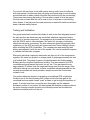
GPS Robot Navigation Final Report
Senior Design Project
Computer Science Department
Dwight Look College of Engineering
Texas A&M University
May 10, 2004
Chris Foley
Kris Horn
Richard Neil Pittman
Michael Willis
Table of Contents
Project Proposal
3
Review of Project
28
Implementation Notes
30
User Manuel
42
Course Debriefing
55
Timeline
57
C-Code
58
MATLAB code
69
2
GPS Navigation for Field Mobile Robots
Project Proposal
Chris Foley
Kris Horn
Richard Neil Pittman
Michael Willis
CPSC 483
February 9, 2004
3
Table of Contents
Introduction
Problem background
3
Needs statement
3
Goal and objectives
3
Method of Solution
Literature and technical survey
4
Design constraints and feasibility
5
Evaluation of alternative solutions
6
Statement of work
Proposed design
8
Research
8
Construction
8
Testing
9
Approach for design validation
10
Mark III Controller Board Kit
10
Garmin 15L Wired GPS
10
Stampede Monster Truck
11
TS-025 Electronic Compass
12
Economic analysis and budget
12
Schedule of tasks, Pert and Gantt charts
13
Project management and team work
16
Societal, safety and environmental analysis
16
Appendices
18
CV/qualifications of team members
19
Bibliography
23
Project Datasheets
24
4
Problem Background
The purpose of this project is for the team of students to design and construct a
vehicle capable navigating to a sequence of. This effect is to be accomplished
using a global positioning system to allow the vehicle to become aware of its
position on the earth and the positions of wave points relative to its current
location. This device must be a robust vehicle capable of traveling outdoors on
mostly flat ground and able to carry the load of what components are necessary
for it to accomplish its function.
Needs Statement
The project will provide the members of the team with experience in the design
process from conception to implementation. This experience will be necessary as
the members of the team go into their careers and seek to participate in projects
of similar and larger complexity.
Furthermore, the project when completed will produce a vehicle capable in part
of self-navigation with users providing the path. This can later be further
expanded to have an artificial intelligent planner decide on the path with users
only providing beginning and ending points. The platform can be used in many
ways depending on what additional hardware is added. Such applications include
information gathering, transportation of small materials, remote presence, and
environmental surveying.
Goals and Objectives
Obvious goals for this project are fulfill the requirements provided by the
professor and teaching assistant. The set goals drawn up between the student
5
team and the professor can be thought of a rubric with which our project will be
judged. The project goals include but are not limited to the following:
•
Interface micro controller with global positioning system
•
Interface micro controller with remote control vehicle
•
Use micro controller to interconnect global positioning system and remote
control vehicle
•
Vehicle will be sturdy enough to cover mostly flat terrain while carrying a
payload of electronic equipment including the global positioning system.
•
Vehicle will be able to establish its own location on earth and use
information from the global positioning system to navigate to a user
defined point.
•
Vehicle will be able to follow a path of points provided by a user.
Literature and Technical Survey
Our team has utilized several resources to familiarize ourselves with the
components that will make up our final project. We researched general GPS
related articles as well as specific data sheets of GPS units. In addition we have
learned about radio controlled cars, and how to modify them. The proposed
design for the GPS unit will incorporate a compass system that has already been
used by a CPSC 483 group from last semester. Our group will need to be familiar
with the literature provided by the compass group from last semester. Below is
the list of resources that we have used so far in researching our project.
www.navtechgps.com
• This site allowed us to learn about several GPS units and compare prices
www.howstuffworks.com
• Contains general information about how GPS units work.
www.junun.org/MarkIII
• Contains documentation of the Mark III board that we are using.
6
www.qkits.com
• Another site that sells electronic kits such as GPS kits.
www.epemag.wimborne.co.uk/lcd1.pdf
• An article titled “How to use Intelligent LCDs”
www.doc.ic.ac.uk/~ih/doc/lcd/operatio.html
• Contains documentation on the HD44780 LCD standards.
http://studentweb.tulane.edu/~jreasor
• This site is the homepage of a Tulane graduate student who is doing a
similar project.
www.oopic.com
• Contains documentation of the OOPIC which is the microprocessor that
we are using.
http://www.superdroidrobots.com/sensors_compass.htm
• Contains information about the electronic compass.
http://www.digitalnemesis.com/catalogue/RLC1/RLC1.htm
• Contains information about an rs232 to TTL converter.
Design Constraints and Feasibility
Through the design process we will be limited by several different types of
constraints.
The first of these constraints is budget. We do not have a fixed limit on how much
we can spend for this project. However we must justify each purchase by making
sure that it is the most cost effective part and that it is necessary to reach the
final goal. We have been asked to keep the project to an approximate cost of five
hundred dollars.
Another constraint of this project is time. We only have one semester to complete
the final product. Therefore we have to be careful in how far we plan to take the
project. Our team must find a medium between a project that is feasible to
7
complete, and a project that is challenging. A major effect of our time constraint
is ordering parts. It will be imperative that parts are ordered as soon as possible
so that we are not waiting on parts to begin construction. It will also be important
that we hold the vendors responsible for shipping our ordered parts in a timely
manner.
The technical scope of our project is yet another possible constraint. This is
partially related to the time constraint. Since we are on a limited schedule, a
project that is too difficult and too technically challenging may not be possible
given the teams experience with this subject. However, our project needs to be
challenging enough so that we are generating the best possible product within
the given time period.
Evaluation of Alternative Solutions
Throughout the initial design process we have come up with several alternative
solutions to various aspects of our project. One solution that we have considered
is not using a compass for the navigation of the RC car. We have considered
using a navigation algorithm that would not require the use of a compass. This
navigation algorithm is based on comparing the RC car’s current location with its
previous location. From that data we can determine which direction the car needs
to turn in order to get closer to its destination. This process would be repeated
every second or so until the destination is reached. Although this solution may
require less hardware, it may not be as accurate as using a compass to
determine which direction the car should turn. In addition, compass navigation
has already been used in a previous project. So, it would be relatively simple to
implement the compass into our system. The compass hardware is already built
and we have access to the software and the documentation of the compass
design as well.
8
Each time the RC car goes to a desired set of GPS, those must be programmed
into the system. One possible method of doing this is having everything needed
to program a new coordinate set located on the car. This would require an LCD
screen to ask the user what to enter, as well as a keypad of that would allow the
user to input the. However this solution may be too difficult to implement given
our time constraints. An alternative solution to programming the new coordinates
would be the use of a PDA or a laptop. For example, whenever a new coordinate
set is desired the laptop or PDA could be hooked up to the system and
reprogrammed via a serial link. Although this solution is not as desirable, it is
more feasible given the scope of this project.
Perhaps one of our primary concerns at this point in the project is being able to
control the RC car. It is difficult to know how we will o about controlling the RC
car since there is not a large amount of documentation publicly available for RC
cars. One possible solution would be to directly tap into the servos of the steering
and the drive motors of the car and completely bypassing the RC car’s controls.
This may be the simplest solution since most servo motors are very similar to
each other, so it would not be very difficult to learn how to control them. However
another proposed solution is to use the remote control of the RC car to move the
car in the desired direction. This would require us to have extensive knowledge
of how the remote control circuit works and may be too difficult. Although, we
may be able to contact the manufacturer of the RC car and get a copy of the
technical documentation which would help us to know how the remote control
functions. Having the documentation would allow us to make a more informed
decision regarding which method of controlling the car would be best.
Throughout the design process we will be faced with possible alternative
solutions to various problems. With each new alternative solution it is imperative
that we evaluate each proposed solution based on budget, time constraints, and
feasibility.
9
Proposed Design
Our project development will involve three stages for completion. The stages in
order are research, construct, and test. These three stages are needed for every
engineering development team. Below is a more detailed description of what
goes on in each stage.
Research
Before any kind of action is done in a project, extensive information gathering
should be performed. Learning more about the product you buy can really save
your budget. Every Monday and Wednesday our group would meet in the lab for
a few hours and research on what major parts were needed for the project. We
wanted only what we needed. Our engineering team decided to save money and
purchase a GPS module rather than a GPS handheld because we did not need
the LCD on the GPS handheld.
Construction
After doing some extensive research we should have a detailed schematic of our
design. Below is a very high level design schematic. As the research
progresses this schematic will get considerably more detailed.
10
Testing
This will be the final stage of our project development. After constructing the car
we will need to run a series of tests. The testing will be done out on the Polo
Fields at Texas A&M University. Our team decided to use these fields because it
was the largest open space that is close to campus. Since GPS modules are
accurate within fifteen meters a large open space is a necessity. Testing the
completed project can be the most stressful.
11
Approach for Design Validation
! Mark III controller board kit (OOPic Version)
The microcontroller will be the heart and brains of our project. We decided to
use the OOPic on the Mark III board. This board is very user friendly and
capable of controlling just about anything. The Mark III board can also be
programmed in Java or C. All of our team members are familiar with the
programming language C. This will greatly help us create an effective algorithm
to navigate the RC truck.
! Garmin 15L Wired GPS + Remote Antenna
The GPS concept is what makes this project unique. We decided to use the
Garmin 15L wired GPS module for a number of reasons. Since the module had
only what we needed we were able to save money. With the antenna the GPS
module was less than $200.
12
The GPS module was also compact. The Garmin 15L wired GPS unit is barely
larger than an American quarter. The small size makes construction easier since
we could basically place the module anywhere on the car.
! Stampede Monster Truck
We decided to use a pre-assemble remote control truck to navigate globally. The
Stampede Monster Truck was ideal for our situation. Not only was the truck
affordable but it was also large enough to conquer the grass out on the Polo
Fields. The remote controlled truck has a ground clearance of about four inches.
The only obstacle stopping this truck is a tree.
The Stampede Monster Truck also has a large pay load capacity. The truck is
roughly 12x16 inches in area. This will provide adequate space for the electronic
parts and components needed to navigate this truck by GPS.
13
! TS-025 Electronic Compass
We decided to use an electronic compass to tell the microcontroller the direction
the truck is facing. A friend of one of the group members referred the TS-025
Electronic Compass. This compass is affordable, easy to use, and extremely
accurate (within a tenth of a degree).
Economic Analysis and Budget
Below is a rough estimate of our budget to complete the project. As with all
projects, problems can and will arise, causing the need for additional funding.
However, here is a list of the major parts that will be needed. The other parts like
resistors, capacitors and amps should not drastically raise our budget.
14
Stampede Monster Truck
154.99
TS-025 Electronic Compass
45.00
Mark III Electronic Board Kit
49.00
GPS Module + Antenna
99.95 + 69.95
Subtotal
≈ $420.00
Schedule of Tasks, Pert and Gantt Charts
Monday – 4:40 pm (15 minute meeting with faculty)
Monday – 6:00 pm (meeting with TA)
Wednesday – 4:10 (engineering group meeting)
15
16
17
18
Project Management and Team Work
We have decided to generally divide the work as follows:
Kris Horn: GPS hardware integration.
Chris Foley: Software design, budget, procurement of parts.
Neil Pittman: PIC Microcontroller specialist and hardware design.
Mike Willis: Software and board design.
Societal, Safety, and Environmental Analysis
A GPS guided mobile robot presents many benefits and changes to society. One
of the largest impacts may be in warfare. A GPS guided robot will have the
ability to travel to places where it may be dangerous for humans to travel. While
traveling, features and sensors could be added to the robot to detect various
things. For example, a GPS guided robot could be sent into a mine field to try
and find the locations of mines. If a mine triggers during the process, it is far
better to loose the robot than a human life. This robot’s application could be
extended to various other situations in warfare and in everyday life. The main
idea behind it is that we can send a robot to places that are unsafe for humans or
that humans would have difficulty getting to. This could definitely change warfare
and scientific research at the least.
The safety concerns associated with this robot are minimal. Normal care should
be taken when operating electrical equipment and caution should be placed
when setting the for the robot’s path. It will be important to make sure that the
robot will not take a path that could lead to undesirable damage.
Finally, the GPS guided mobile robot should not have too much of an effect on
the environment. If the batteries ever need replacing, it is necessary to properly
dispose of the used batteries. Also, it will be important to make sure that the
19
robot does not traverse any ground on which it may have a negative effect on the
surroundings. Unless it is intentional, it should be plotted to avoid sensitive
areas.
20
Appendices
•
CV/qualifications of team members
•
Bibliography
•
Product datasheets
21
Resume for CPSC 483 – Computer System Design
Section 502
Christopher Foley
[email protected]
979.574.1506
GPA: 3.704
Project:
1) Integrating GPS and Robots
Courses/Electives:
Microcomputer Systems, Networking, Databases, E-Commerce
Interests/Skills:
I am very interested in learning and working with GPS systems and how to
integrate GPS with other systems. I feel that my skills are about equivalent when
it comes to hardware and software. I honestly do not have a lot of experience
with either one but I would like to gain and a fairly good understanding of both. I
have less exposure to hardware design than software design so I would like to
use this course to help me gain more experience with some hardware design. I
took microcomputer systems last semester and I enjoyed trying to learn how to
design hardware systems although I still have a lot to learn. On the other hand,
my electrical engineering background is not too strong so I’m sure I will have to
do some research to get a good understanding of things.
Schedule:
Monday:
Tuesday:
Wednesday:
Thursday:
Friday:
Class/Work from 10:00 to 7:00 (Including this class and lab)
Class/Work from 9:00 to 5:15
Class/Work from 10:00 to 7:00 (Including this class and lab)
Class/Work from 9:00 to 5:15
Class from 10:20 to 11:10
22
MICHAEL WILLIS
1114 S. Dexter
[email protected]
College Station, TX 77840
979-574-7169
1999-Present
Texas A&M University
TX
1 Pursuing B.S. in Computer Engineering
2 G.P.R. 3.136
3 Texas A&M Men’s Lacrosse Team: 4 years
College Station,
EDUCATION
WORK EXPERIENCE
2002-Present
Texas A&M University
College Station,
TX
1 Help Desk Central Computing and Information Services
- phone/walk-up computer support for Texas A&M students and
staff
- dealt with the campus network, virus traffic, email and much
more
2002-Spring
Texas A&M University
Station, TX
2 Intramural Soccer Official
Summer 2001
Kohutek Engineering
Austin, TX
3 Engineering Technician for a Civil Engineer
-field/lab testing for construction sites
-Concrete testing, soil analysis, soil sample drilling
ELECTIVES
CPSC 436 Computer Human Interaction
CPSC 463 Networks (current semester)
CPSC 310 Databases (current semester)
SPAN 101, 102, 201, 202 - Spanish
PSYC 315 Social Psychology
SCOM 203 Public Speaking
PROJECT CHOICES
1)
2)
3)
4)
Sonar Fusion on PDA
Hack Furby
Wearable Sensors
Integrating GPS and Robots
23
College
INTERESTS
My interests lie more in hardware than programming.
Other than that I don't really know yet what I am interested in.
I can only attend the section 502 lab time.
Richard Neil Pittman
P.O. Box 14416
College Station, TX, 77841
(979) 847-6098
[email protected]
Academics
Senior Computer Engineering Major, Computer Science Track.
Minor in Mathematics.
Texas A&M University, College Station, Texas.
Current Cumulative GPR 3.57.
Elective Classes
Interest
CPSC 625, Artificial Intelligence.
MATH 470, Cryptography & Communications.
CPSC 310, Databases.
Artificial Intelligence & Robotics. - In the past year I
have discovered a great interest in robotics and AI. This
has lead me to seek information about the subject and
would like an oppurtunity to apply what I have learned and
to learn more.
Networks & Distributed Systems. - My interest in networks
involves it use as a method of gathering and distributing
data in an intelligent manner in order to provide services.
Web applications could also be added to some projects to
expand their utility.
Cryptography. - While this may not be used directly for any
project, this background gives me unique perspective which
may be useful for finding patterns in data.
Class Schedule
CPSC 463-500, Networks TR 3:55-5:10
CPSC 483-502, Computer Sys Design MW 4:10-7:00
KINE 199-287, Strength Train-Beginning TR 8:00-10:50
KINE 199-039, Archery-Beginning TR 9:35-10:50
Project Preference 1. Integrating GPS & Robot
2. Robot Learning & Whiskers
3. Facial Tracking
4. Navigate Maze
5. Hack Furby
6. Wearable Sensors
24
7. Sonar Fusion of PDA
8. Coff-e-mail
9. Circadian Circuits
25
KRISTOPHER J. HORN
Permanent Address
2910 Rolling Hills Dr.
Carrollton, TX 75007
(214) 906-0844
Campus Address
117 Holleman Dr. W. #3308
College Station, TX 77840
[email protected]
OBJECTIVE
To obtain a summer and fall 2005 coop.
EDUCATION
Texas A&M University
Dwight Look College of Engineering
Bachelor of Science in Computer Engineering
Minor in Mathematics
Overall GPA 3.36
September 2000 - May 2004
College Station, Texas
SKILLS
Languages: Java, some C, MIPS, Verilog, Ada, and HTML
Platforms: Windows and some UNIX
EMPLOYMENT
Winter 2002
•
Netco Title Solutions, Filer
Organized policy files.
Summer 2002 Papa Johns, Delivery Driver
•
Delivered food orders to customers.
Arlington, Texas
Dallas, Texas
AFFILIATIONS
Summer 2003 Undergraduate Math Research
•
Research Program in Combinatorial Theory
2002-Present
Institute of Electrical and Electronics Engineers, (IEEE).
2002-2003
•
Recreational Sports Intramural
Competed in soccer, El Guapo, Forward
QUALLIFICATIONS
• Familiar with PIC Microcontrollers
• Knowledge of using DC motors and servos
26
Bibliography
www.navtechgps.com
• This site allowed us to learn about several GPS units and compare prices
www.howstuffworks.com
• Contains general information about how GPS units work.
www.junun.org/MarkIII
• Contains documentation of the Mark III board that we are using.
www.qkits.com
• Another site that sells electronic kits such as GPS kits.
www.epemag.wimborne.co.uk/lcd1.pdf
• An article titled “How to use Intelligent LCDs”
www.doc.ic.ac.uk/~ih/doc/lcd/operatio.html
• Contains documentation on the HD44780 LCD standards.
http://studentweb.tulane.edu/~jreasor
• This site is the homepage of a Tulane graduate student who is doing a
similar project.
www.oopic.com
• Contains documentation of the OOPIC which is the microprocessor that
we are using.
http://www.superdroidrobots.com/sensors_compass.htm
• Contains information about the electronic compass.
http://www.digitalnemesis.com/catalogue/RLC1/RLC1.htm
• Contains information about an rs232 to TTL converter.
27
Project Datasheets
Attached are some of the project datasheets for parts of our project.
28
Review of Project
Problem Background
Today many electronic devices are automated, and unmanned. There are many
applications in which having an unmanned robot is safe and can save human
lives. An example is a robot that travels into a mine field to detonate a dangerous
mine. This robot could use GPS coordinates to navigate to a specific location to
perform the necessary tasks. In addition there must be some form of obstacle
avoidance. One example would be the use of sonar devices to avoid obstacles.
Needs Statement
With so many dangers arising today and because of the advancement of
technology, there is a need for automated and unmanned devices. The military
has a need for GPS guided systems to protect the lives of soldiers. Civilians also
could benefit from GPS guided systems by making everyday navigation easier
and safer.
Goals and Objectives
Our goal is to develop a GPS guided system that will successfully navigate to a
series of pre-defined coordinates.
Our objectives consist of the following:
• Develop a system that will be sturdy enough to cover mostly flat terrain
while carrying a payload of electronic equipment including the global
positioning system
• Develop a system that will be able to establish its own location on earth
and use information from the global positioning system to navigate to a
user defined GPS coordinate
• Vehicle will be able to follow a path of points provided by a user
• Vehicle will be able to avoid obstacles along the way, and still navigate to
the user defined coordinates
Literature and Technical Survey
Our team has utilized several resources to familiarize ourselves with the
components that will make up our final project. We researched general GPS
related articles as well as specific data sheets of GPS units. In addition we have
learned about radio controlled cars, and how to modify them. The proposed
design for the GPS unit will incorporate a compass system that has already been
used by a CPSC 483 group from last semester. Our group will need to be familiar
29
with the literature provided by the compass group from last semester. Below is
the list of resources that we have used so far:
www.navtechgps.com
• This site allowed us to learn about several GPS units and compare prices
www.howstuffworks.com
• Contains general information about how GPS units work.
www.junun.org/MarkIII
• Contains documentation of the Mark III board that we are using.
www.qkits.com
• Another site that sells electronic kits such as GPS kits.
www.epemag.wimborne.co.uk/lcd1.pdf
• An article titled “How to use Intelligent LCDs”
www.doc.ic.ac.uk/~ih/doc/lcd/operatio.html
• Contains documentation on the HD44780 LCD standards.
http://studentweb.tulane.edu/~jreasor
• This site is the homepage of a Tulane graduate student who is doing a
similar project.
www.oopic.com
• Contains documentation of the OOPIC which is the microprocessor that
we are using.
http://www.superdroidrobots.com/sensors_compass.htm
• Contains information about the electronic compass.
http://www.digitalnemesis.com/catalogue/RLC1/RLC1.htm
• Contains information about an rs232 to TTL converter.
The Devantech SRF04 Ultrasonic Range Finder
• This is the data sheet for the Sonar devices that we are using
Optical EC Encoder Kit Documentation from US Digital
• This is the data sheet for the optical encoder that we are using
30
Implementation Notes
OOPic and S control board
The OOPic is a programmable microcontroller used to run the code
necessary to accomplish navigation function. This is possible through reading
sensory input data and sending command via its input/output pins to other
components via its input/output pins. The OOPic is mounted on the S control
board providing it with power, easy access to input/output pins and an interface
to the EEPROM where programs running on the OOPic are stored and read
from.
OOPic stands for Object Oriented Pic. The most notable feature of this
microcontroller is the number objects available to its users when writing code.
These objects make interfacing the OOPic with a number of popular devices and
implementing hardware capabilities in the microcontroller very simple for anyone
who has experience in object-oriented programming. This by itself has made the
OOPic very popular for those seeking a controller that can be learned quickly and
used in low to mid-level applications.
The S control board includes all of the connections and functionality
required operates the OOPic. The board includes two EEPROM sockets. One is
specifically for storing the program to be run and the other may be used for
storing data. The power connector connects a 9 volt battery connector to provide
power to the OOPic and board components. We not would recommend using
the connector that comes with the board because the connection over time with
constant use was not very good. Beside the power connector is the reset button
which can be used to reinitialize the OOPic and restart the stored program.
Finally, there are the programming and network connectors that can all connect
to the 4 pin interface side of the programming cable. To program the OOPic you
plug the programming into the parallel port of a computer and the other into the
programming connecter and follow the instructions in the documentation at
31
www.oopic.com or our user manual. The network connectors are connected to
the I2C serial communications bus and can be used for debugging. For
instructions on using this function look at the www.oopic.com or our user manual.
The OOPic is a 40 pin chip including VCC (line 4), GND (line 2), two 5 volt
power supplies (lines 21 & 22), two ground (lines 23 & 24), Reset (line 5), and an
I2C serial bus (data line on line 1 and clock line on line 3). The OOPic has 31
input/output lines (lines 6 through 19 and 25 through 40) some of them with
special functions. Line 25 (IO Line 16) and Line 27 (IO Line 17) are Timer
interrupt lines. Line 27 (IO Line 17) and Line 29 (IO Line 18) are Pulse Width
Modulation lines. Line 31 (IO Line 19) is an additional I2C data line and Line 33
(IO Line 20) is an additional I2C clock line. Line 37 (IO Line 22) is the serial
transmit line for TTL level communications and Line 39 (IO Line 23) is the serial
receive. For additional documentation on the mechanical specifications of the
OOPic with the S control board go to www.oopic.com # Manual # OOPic
connectors and mechanical # S style board.
The OOPic Multi-Language Compiler provided and large number of
objects available to make the process of writing code easier. For our project we
used a large number of these objects including the oDCMotor, oI2C, oServoSP1,
oLCD, oClock, oEvent and oSerial. All these behavior like you would expect
objects to behave in other programming environments.
Declarations
Object Type Name = New Object Type;
Attributes
Name.Attribute = value
Othervar = Name.Attribute
Additional documentation on the objects and coding conventions of the OOPic go
to www.oopic.com # Manual.
Printed Circuit Board Design and Component Layout
The hardware on the RC car is centered on the printed circuit board in the middle
of the car. Each component on the car plugs into the two layer printed circuit
board. The board was designed using the software from www.expresspcb.com;
the board was purchased from ExpressPCB.com as well. There is a 40 pin
ribbon cable connector on the PCB that allows a ribbon cable to be connected to
the OOPIC Microprocessor (See figure labeled PCB below). The inputs on the
PCB include GPS, sonar, compass, and battery. In addition the PCB has spots
for additional circuitry and components. There are spots for the RS232 to TTL
Converter chip, capacitors, a potentiometer, a voltage regulator, and a DB-9
Serial connector. Each of these components must be soldered into the PCB. The
figure labeled Schematic is a schematic of how each of the components of the
car fit together. The Schematic and the PCB layout are different from the
32
schematic in order to fit each component on a small enough board to mount on
the car; the board size is 2.5” x 3.8”.
Each component is mounted on the car according to where it is needed. For
example the sonar devices of course are mounted on the front of the car. The
compass is also mounted towards the front of the car in order to be the furthest
away from the electronic noise of the motors and batteries. The figure labeled RC
car is a photograph of the final car. The figure labeled Schematic show where on
the car each of the components are located.
PCB – Printed Circuit Board Layout
33
Schematic – Schematic layout of the components on the RC car
RC Car – The Final Product Without the Cover
34
Schematic – Schematic of the Final RC Car
Velocity Control
The velocity control for the GPS navigated robot was more difficult to
configure than first expected. We used a circuit called an “H-Bridge” to interface
the motor to the OOPic. This allowed the OOPic to control the power, or velocity,
of the robot. The H-Bridges we used burned out because the DC motor drew to
much current for the H-Bridges to handle. After our second H-Bridge burning out
we decided to just reengineer the controller from the truck. This would allow us
to use an electronic speed controller, a powerful MOSFET circuit that RC cars
use, to power the robot.
35
Hacking the Controller
We used the controller that came with the Traxxis Rampage truck, above picture,
to control the speed of the robot. The controller had to be torn apart to study how
the electronics worked.
Since we only needed to manipulate the throttle we ignored any of the
steering circuits, as best we could. The throttle was just a fancy potentiometer.
The potentiometer was fed 4 volts, with the output voltage dictating how much
power was fed to the motor. Actually, the output voltage was fed to an integrated
circuit that sent signals to the antenna to be received by the receiver on the car.
Since we only needed to mimic the output voltage there was no reason on
studying how the circuitry worked any further.
The output voltage ranged from 1.5 to 2.4 volts, 1.5 being standstill and
2.4 being full throttle. To impersonate the potentiometers voltage we needed a
DAC (Digital to Analog Converter) or a creative way to represent the voltages in
that range. We decided not to use a DAC for a couple of reasons, one reason is
that the interface for the DAC was not very foretelling and second, we did not
have enough I/O lines available from our OOPic.
Since the output of the OOPic was TTL, voltage ranging from 0 to 5, we
decided to use one of the I/O lines to represent the output voltage from the
potentiometer. In order to do this we had to use PWM (Pulse Width Modulation)
on one of the I/O lines. PWM is used mainly to control DC motors by varying the
on time of a cycle. The picture below shows a good example of how PWM
works. PWM allowed our OOPic to represent any voltage between 0 and 5 volts
with one IO line.
36
In order to impersonate the potentiometer we needed to smooth out the PWM
signal. The constant on and off waveform caused our robot to have choppy
throttle response. To make the PWM smoother we used three 4.7 micro-farad
capacitors. This greatly smoothed out the signal and thus rounded out our
throttle control.
The picture below show the circuit board we tore out of the controller and
placed on our truck.
37
Navigation Code
To understand the navigation code, it is best to start with a high level approach
and work downwards. A copy of the code is located in the appendix of this
document and may be useful with the following discussion. The abstract design
of the navigation code is represented in the following diagram.
Navigation System
Path Navigator
Heading Navigator
Steering Control
Motor Control
Obstacle Avoidance
GPS
Sonar
Compass
Abstract Navigation System Design
The navigation system at the top takes the inputs from the path navigator and
passes them to the steering and motor control. This is primarily represented in
the main subroutine of our code.
Sub void main(void)
{
Setup;
while (curDest < numDests)
{
cycle = cycle + 1;
cycle = cycle % 4;
if (cycle == 1)
{
GetGPSReading;
GetDxDy;
GetAfn;
}
heading = Compass.Value/10;
UpdateLCD;
if ((dxa > 1) | (dya > 1))
{
GetPathNavInfo;
Steer;
}
else
{
curDest = curDest + 1;
GetDest;
GetGPSReading;
GetDxDy;
GetAfn;
}
38
}
motor.value = 135;
LCD.Locate(0,31);
LCD.String = "done";
}
The while loop is repeated until the final destination has been reached. The first
section of the loop gets the path navigator information. Once this information has
been received, the code uses it to control the robot accordingly. The Steer
subroutine controls the robot’s steering servo and will turn it to the left, right or
straight. Once a destination has been reached, the navigation system moves on
to the next destination in the destination list. This is accomplished through the
GetDest subroutine. When the last destination has been reached, the code will
exit the loop and send the motor a value to stop. It will also print “done” on the
LCD.
The path navigator portion of the code is primarily contained within the
GetPathNavInfo subroutine. The code for this section is as follows.
Sub void GetPathNavInfo(void)
{
GetObstInfo;
if (obsLR == 1)
{
GetObstTurnDir(frtRS);
turndir = mul(65535,turndir); //-1*turndir
LCD.Locate(1,11);
LCD.String = "L";
}
else if (obsLR == 2)
{
GetObstTurnDir(frtRS);
turndir = mul(65535,turndir); //-1*turndir
LCD.Locate(1,11);
LCD.String = "C";
}
else if (obsLR == 3)
{
GetObstTurnDir(frtLS);
LCD.Locate(1,11);
LCD.String = "R";
}
else
{
GetTurnDir;
LCD.Locate(1,11);
LCD.String = "N";
}
}
The main purpose of the path navigator is to determine whether the robot should
head for the target destination or avoid an obstacle. If the obstacle detection
system detects an obstacle, the control commands for avoiding an obstacle will
override the normal commands provided by the heading navigator section.
39
The obstacle avoidance system is represented in the subroutine GetObstInfo.
This function checks the sonar feedback and determines the location of an
obstacle if present. The GetObstInfo subroutine is shown below.
Sub void GetObstInfo(void)
{
rsonar.Operate = 0;
rsonar.Operate = 1;
lsonar.Operate = 0;
lsonar.Operate = 1;
while ((rsonar.Received == cvFalse) & (rsonar.TimeOut == cvFalse)) {}
if ((rsonar.TimeOut == cvFalse) & (rsonar/64 <= 10))
frtRS = rsonar/64;
else
frtRS = 255;
while ((lsonar.Received == cvFalse) & (lsonar.TimeOut == cvFalse)) {}
if ((lsonar.TimeOut == cvFalse) & (lsonar/64 <= 10))
frtLS = lsonar/64;
else
frtLS = 255;
if (frtRS < frtLS)
{
obsLR = 1;
}
else if (frtRS > frtLS)
{
obsLR = 3;
}
else if (frtRS == frtLS)
{
if (frtRS == 255)
{
obsLR = 0;
}
else
{
obsLR = 2;
}
}
}
Sending a positive edge to the sonar will trigger a ping to be sent out. If an echo
is received the value, in feet, will be noted and compared to the other sonar. The
code will then determine where the closet obstacle is at, if any, and record this in
the variable obsLR. The navigation system then uses this information to
determine the path of travel.
The final subsystem of the navigation code is the heading navigator. The
heading navigator uses the current GPS coordinates along with the destination
coordinates and the compass reading to determine the direction to steer the
robot. This is represented as a combination of the GetDxDy, GetAfn, and
GetTurnDir subroutines shown below.
Sub void GetDxDy(void)
{
if (DestLng >= Lng)
{
40
dxa = DestLng - Lng;
dx = mul(65535,dxa); //-1*dxa (opposite because longitude is given as
positive to the west)
}
else
{
dxa = Lng - DestLng;
dx = dxa;
}
if (DestLat >= Lat)
{
dya = DestLat - Lat;
dy = dya;
}
else
{
dya = Lat - DestLat;
dy = mul(65535,dya); //-1*dya
}
}
Sub void GetAfn(void)
{
if (dxa == 0)
afn = 0;
else if (dya == 0)
afn = 90;
else if (dya <= dxa)
{
index = dya*16;
index = index/dxa;
GetArctan;
afn = 90 - afn;
}
else
{
index = dxa*16;
index = index/dya;
GetArctan;
}
if ((dx
afn =
else if
afn =
else if
afn =
> 32767) & (dy < 32768)) //quadrant 2
360 - afn;
((dx > 32767) & (dy > 32767)) //quadrant 3
180 + afn;
((dx < 32768) & (dy > 32767)) //quadrant 4
180 - afn;
}
Sub void GetTurnDir(void)
{
turndir = sbt(heading,afn);
while (turndir > 32767)
{
turndir = add(turndir,360);
}
if (turndir > 180)
{
turndir = sbt(360,turndir);
turndir = mul(65535,turndir);
}
LCD.Locate(0,14);
printNum(turndir);
41
turndir = div(turndir,3);
turndir = add(turndir,div(intBearingSum,100));
intBearingSum = add(intBearingSum,turndir);
}
The GetDxDy subroutine simply determines the distance between the current
latitude and longitude and the destination latitude and longitude. The GetAfn
subroutine then uses this information to determine the angle of the destination
from the current position relative to north. This calculation uses an
approximation to arc tan since the OOPic does not support inverse trig functions.
This approximation is located in the GetArcTan subroutine and is accurate to
approximately three degrees. Once the angle of the destination relative to north
is calculated, the GetTurnDir subroutine subtracts this value from the heading in
order to determine the angle from heading. Based on this angle, the turn
direction for the robot is calculated using a proportional and integral calculation.
One final point about the code is the use of our own numbering system for all
numbers that could have negative values. The need for this system arose when
we encountered problems while trying to use negative values for some of the
variables. The oWord and oByte objects in the OOPic are supposed to be able
to handle negative values. However, after doing some simple tests, we
discovered that we could not rely on the results the OOPic would give us.
Therefore, our system uses the Word data type which has an integer range from
0 to 65535. Positive numbers range from 0 – 32767 and negative values range
from 65535 – 32768 were -1 equals 65535 and -32767 equals 32768. We then
created add, subtract, multiply, and divide functions for basic arithmetic with this
system.
All of this code was originally created in MATLAB in order to test the results
before transferring it to the robot. The MATLAB code is also included in the
appendix. The main difference between the MATLAB code and the C code is
that the sensory inputs (i.e. GPS coordinates, compass, and sonar) had to be
simulated since we could not integrate them into MATLAB.
42
User Manual
Operating the Robot Car
Operation of the GPS guided robot car can be broken up into the following
steps: Preparing the course, Modifying source code for desired coordinates,
Programming the robot car control board, Remove Cover, Connecting Batteries,
Replace Cover and Activating robot car systems.
Preparing the Course
Before any modifications can be made to the robot car the course that it
will run must be investigated and prepared. First go out to the site where the
course will be and investigate the site for suitability. Take special care with
regard to wet ground due prevent damage to electronics and tall grass that could
interfere with sonar or impede the drive of the car. Next, select points on the site
to create a course or path and walk the course taking careful note of any terrain
features such as ledges or natural obstacles the robot cars systems will not be
able to traverse. These include but are not limited to large bodies of water and
sudden drops in elevation. Finally, record your path coordinates for
programming the robot car.
Modifying Source Code
To modify the source code of the robot car to navigate to desired
coordinates, look in the GetDest subroutine and simply add the coordinates of
the destinations into the list.
Programming the Robot Control Board
To program the robot control board after modifying and saving the source
code file, nav.osc, follow the instructions at www.oopic.com or our user manual
for Programming the OOPic from a file.
Remove Cover
To remove the top truck shaped cover of the robot car, remove the four
cotter pins. Then carefully left off the cover from the car and set it aside.
Connect Batteries
43
To operate the GPS guided car you must install the 7.2V motor battery
and two 9V batteries. Place the 7.2V battery on the tray on the right of the car
orientated from the rear. Next, locate the electronics battery connected towards
the front of the car and the OOPic 9V connector towards the rear. Insert a 9V
battery into each of these.
Replace Cover
Carefully place the truck shaped cover on the robot car and make sure
that the support pegs on the body of the robot car chassis are protruding through
the holes in the front and the back. Then, insert the cotter pins into these pegs.
Activating the Robot Systems
To activate the GPS guided robot after it was been prepared for its course,
first place the robot can at the starting location. Next, flip the red switch,
orientated from the rear, on the right side of the car behind the front wheels.
Then
Programming & Using the OOPic
Before the OOPic can be used it must be programmed. A great deal of
the project development involved writing programs for the OOPic to interface with
hardware. To program the OOPic, one should go the OOPic website
(www.oopic.com) and download the latest version of the OOPic Multi-Language
Compiler, which at the time of our project was in version 5, and the path for the
parallel cable programming interface for Windows NT, 2000 & XP (Port95nt.exe).
After downloading these two files you must first install the compiler and then the
patch if you are running the compiler on one of the effected operating systems.
44
Preparing the OOPic for Programming
Start the OOPic Multi-Language Compiler open.
To prepare the OOPic for download of a program attach the parallel cable
to the interface at the back of the computer but do not attach it to the four pin
programming connector, yet.. In the compiler software go to Tools#Cable
Configuration and a dialog window will appear.
45
Then press the ‘Find Parallel Cable’ button and you should see the following
change.
46
If the dialog window appears like this you may press ‘Ok’ and the dialog will
close.
Then, go to Tools#Language and select the language syntax that you
would like to use or the language the code you will downloading into the OOPic is
written in (either C, Java, or Basic). All of the developed for our project was
written in C syntax because of our previous experience and familiarity.
47
Finally, go to Tools#Target Device and select the OOPic Firmware Ver.
B.2.x. This is the latest firmware available at the time of our project and
corresponds to the version of the OOPic we have on the control board.
Now, you may attach the 4 pin programming connector to the
programmable cable. You may now program the OOPic.
48
Programming the OOPic from a file
To program the OOPic you must first prepare the OOPic Multi-Language
Compiler and the OOPic for programming as seen at www.oopic.com or our user
manual. When you have done this you may proceed. Start with the OOPic MultiLanguage Software open as shown.
First, go to File#Open and the following dialog will open.
49
Navigate the dialog window to the location of your source file. It will have the
extension *.osc. When you have found the desired file, click on it. Its file name
will appear in the File name text box and you may press the ‘Open’ button.
50
The dialog window will close and the program will open to a window in the
OOPic Mult-Language Compiler environment.
51
To program the OOPic, you may either the button with triangle pointing to
the Right or press F5. The code will compile and download to the EEPROM on
the control board
Using the Network Connectors to Debug Code
To use this function before programming the OOPic in the main body of
the program insert the line: OOPic.Node = #, where # is a number between 1
and 127. Next program the OOPic as it is described at www.oopic.com or in our
user manual.
52
Then in the OOPic Multi-Language Compiler environment click on the icon
labeled ‘NETWORK NODE()’ in the right pane and the following dialog will
appear.
In the field labeled ‘Node:’ enter the same number you entered for # in the line of
code you inserted in your code on the previous step. Press the ‘Set’ button and
the dialog will close. Next, reset the OOPic by pressing the reset button on the S
control board by the power connector.
53
Now, while the program is running you may double-click on any of the icons in
the right pane of the OOPic Multi-Language Compiler environment as shown.
These icons represent objects you have declared in your program and when you
double-click on them a dialog similar to the following will appear.
54
These dialog windows will vary with the objects they are associated with them.
In these dialog windows you can view the current values of the attributes
associated with that object. However, they do not update automatically. In order
to view the value of an attribute at any given time the user must press ‘Refresh’
button to update the values. When you are finished you press the ‘x’ button in
the upper right corner of the dialog window and it will close.
55
Course Debriefing
Group Management
The management style of our group turned out to work successfully. We all were
responsible for our own portions of work but we helped each other out and kept
each other on track as well. For the most part, we each had a specialty area in
our project. Neil and Kris both focused on the hardware and worked together
well to figure out how to interface with the motor, compass, steering servo, and
sonar. On the other hand, Chris and Mike focused on the software, integrating
the GPS with the system, and many of the problems that arose. After we
finished the individual components, we worked together to integrate the parts and
compose the system as a whole.
If we were to do the project again, we would do most of the management the
same as we have. The only thing that we would change would be assigning
deadlines as much as possible for individual parts of the project. This would help
us to ensure that we don’t get behind with any one part of the project.
Societal, Safety, and Environmental Analysis
A GPS guided mobile robot presents many benefits and changes to society. One
of the largest impacts may be in warfare. A GPS guided robot will have the
ability to travel to places where it may be dangerous for humans to travel. While
traveling, features and sensors could be added to the robot for various detection
needs. For example, a GPS guided robot could be sent into a mine field to try
and find the locations of mines. If a mine triggers during the process, it is better
to loose the robot than a human life. This robot’s application could be extended
to various other situations in warfare and in everyday life. The main idea behind
it is that we can send a robot to places that are unsafe for humans or that
humans would have difficulty getting to. This could definitely change warfare and
scientific research at the least.
The safety concerns associated with this robot are minimal. Normal care should
be taken when operating electrical equipment and caution should be placed
when setting the coordinates for the robot’s path. It will be important to make
sure that the robot will not take a path that could lead to undesirable damage.
Finally, the GPS guided mobile robot did not have much of an effect on the
environment. We used rechargeable batteries in order to minimize the effect on
the environment. There are no emissions of the RC car, since everything on the
car is operated by electricity. It was important to make sure that the robot did not
traverse any ground on which it may have a negative effect on the surroundings.
56
For our test site we chose a low traffic grassy area in order to avoid collisions
with other people. Another step that our group could have taken to ensure safety
would have been to add a remote kill switch that would shut off the car remotely.
There were times during the testing of the car when it sped off at a fast speed.
We then had to chase after the car in order to turn of its power to avoid hitting
other objects. If we had more time and resources a remote kill switch would have
been a valuable safety feature.
Testing and Verification
Our group tested each module individually as well as the final integrated product.
As each product was developed, we tested that individual component before
moving on to another component. For example we first tested the sonar devices
with the OOPIC and no other hardware. We tested it’s accuracy of detecting
objects as well as its consistency. We also extensively tested the accuracy and
consistency of the GPS by driving six times around the Texas A&M golf course
while recording the GPS coordinates. The compass also was tested by itself
before we integrated it with the rest of the system. We used a handheld compass
to validate the electronic compass.
After each individual component was tested, we then put all of the components
together. We tested our product on a large patch of grass approximately the size
of a football field. This patch of grass is located between the Oceanography
Building and the Langford Architecture building. First we measured one GPS
coordinate and programmed that point into our car. Then we placed the car
approximately 30 meters from the target and facing away from the target. After
sufficiently testing one coordinate, another coordinate was programmed into the
car and we repeated the same procedure except we used two coordinates
instead of one.
Our product achieves the goal of navigating to predefined GPS coordinates.
However due to the drive system often it does not take the best path to the
coordinate and may need a small “push” at times to get through thick patches of
graph. If we had more time, we would more thoroughly test the obstacle
avoidance portion of our project. We have tested the obstacle avoidance without
the motor running however we have not sufficiently tested and modified the
obstacle avoidance portion of the car.
57
Timeline
The following Gantt chart shows how are time ended up being allocated
throughout the semester.
58
Appendix
C-Code
//***** LCD Variables *****
oLCD LCD = new oLCD;
//***** GPS Variables *****
oSerial gps = new oSerial; // uses I/O Line 23 (pin 39)
Byte counter;
Byte string[11];
Word Lat;
Word Lng;
Word prevLat;
Word prevLng;
Byte cycle;
//***** Motor Variables *****
oPWM motor = new oPWM;
//***** Compass Variables *****
oI2C Compass = new oI2C;
//***** Steering Variables *****
oServoSP1 StrServo = new oServoSP1;
//***** Sonar Variables *****
oSonarDV rsonar = New oSonarDV;
oSonarDV lsonar = New oSonarDV;
Byte frtRS;
Byte frtLS;
Byte obsLR; //1=left, 2=center, 3=right
//***** Destination Variables *****
Byte numDests;
Byte curDest;
Word destLat;
Word destLng;
//***** State Variables *****
Word heading;
Word turndir;
Word afn;
Word dx;
Word dy;
Word dxa;
Word dya;
Word it;
Byte index;
//***** Integrator Variables *****
//Word intBearingSum;
//*******************************************************************************
Sub void main(void)
{
Setup;
59
while (curDest < numDests)
{
cycle = cycle + 1;
cycle = cycle % 4;
if (cycle == 1)
{
GetGPSReading;
GetDxDy;
GetAfn;
}
heading = Compass.Value/10;
UpdateLCD;
if ((dxa > 1) | (dya > 1))
{
GetPathNavInfo;
Steer;
}
else
{
curDest = curDest + 1;
GetDest;
GetGPSReading;
GetDxDy;
GetAfn;
}
}
motor.value = 135;
LCD.Locate(0,31);
LCD.String = "done";
}
Sub void GetDest(void)
{
if (curDest < numDests)
{
switch (curDest)
{
Case 0:
destLat = 37097; //latitude
destLng = 20234; //longitude
break;
Case 1:
destLat = 37093; //latitude
destLng = 20218; //longitude
break;
}
}
}
Sub void Setup(void)
{
OOPic.Node = 3;
//***** destination setup *****
curDest = 0;
numDests = 2;
GetDest;
//***** navigation setup *****
60
//intBearingSum = 0;
turndir = 0;
//***** sonar setup *****
rsonar.IOLineP = 3;
rsonar.IOLineE = 4;
rsonar.Operate = 1;
lsonar.IOLineP = 18;
lsonar.IOLineE = 19;
lsonar.Operate = 1;
frtRS = 255;
frtLS = 255;
obsLR = 0;
//***** gps setup *****
gps.Baud = cv1200; // Baud rate is set to 2400
gps.Operate = cvTrue;
prevLat = 0;
prevLng = 0;
cycle = 0;
//***** lcd setup *****
LCD.IOLineRS = 27; //(pin 34) RS line to the LCD module
LCD.IOLineE = 26;
//(pin 36) E line to the LCD module
LCD.IOGroup = 3; //I/O lines 28-31 (pins 32-26)
LCD.Nibble = 1; //Upper half of data (d4-d7)
LCD.Operate = cvTrue;
OOPic.delay = 3; //wait for LCD to come up
LCD.Init; //Perform LCD initialization
OOPic.delay = 50;
LCD.Clear; //clear the screen
LCD.Locate(0,0); // positions the cursor at the star
LCD.String = "HERBIE!!!!!";
OOPic.delay = 100;
LCD.Clear;
LCD.Locate(0,0);
LCD.String="LAT: ";
LCD.Locate(1,0);
LCD.String="LNG: ";
LCD.Locate(0,20);
LCD.String="CMP: ";
LCD.Locate(1,20);
LCD.String="X: ";
LCD.Locate(0,11);
LCD.String = "A:";
LCD.Locate(1,28);
LCD.String = "Y:";
//***** servo setup *****
StrServo.IOLine = 1;
StrServo.Operate = cvTrue;
//***** compass setup *****
Compass.Node = 96; // Decimal of Hex address 0xC0 shifted right by 1
Compass.Mode = cv10bit; // I2C mode is 10-Bit Addressing.
Compass.NoInc = 1; // Don't increment
Compass.Location = 2; // Address of single byte bearing
Compass.Width = cv16bit; //Compass Data is 1-byte wide.
//***** motor setup *****
61
motor.IOLine = 17; //pin 29
motor.prescale = 3;
motor.period = 255;
motor.Operate = 1;
motor.Value = 176;
}
Sub void GetPathNavInfo(void)
{
GetObstInfo;
if (obsLR == 1)
{
GetObstTurnDir(frtRS);
turndir = mul(65535,turndir); //-1*turndir
LCD.Locate(1,11);
LCD.String = "L";
}
else if (obsLR == 2)
{
GetObstTurnDir(frtRS);
turndir = mul(65535,turndir); //-1*turndir
LCD.Locate(1,11);
LCD.String = "C";
}
else if (obsLR == 3)
{
GetObstTurnDir(frtLS);
LCD.Locate(1,11);
LCD.String = "R";
}
else
{
GetTurnDir;
LCD.Locate(1,11);
LCD.String = "N";
}
}
Sub void GetObstInfo(void)
{
rsonar.Operate = 0;
rsonar.Operate = 1;
lsonar.Operate = 0;
lsonar.Operate = 1;
while ((rsonar.Received == cvFalse) & (rsonar.TimeOut == cvFalse)) {}
if ((rsonar.TimeOut == cvFalse) & (rsonar/64 <= 10))
frtRS = rsonar/64;
else
frtRS = 255;
while ((lsonar.Received == cvFalse) & (lsonar.TimeOut == cvFalse)) {}
if ((lsonar.TimeOut == cvFalse) & (lsonar/64 <= 10))
frtLS = lsonar/64;
else
frtLS = 255;
if (frtRS < frtLS)
{
62
obsLR = 1;
}
else if (frtRS > frtLS)
{
obsLR = 3;
}
else if (frtRS == frtLS)
{
if (frtRS == 255)
{
obsLR = 0;
}
else
{
obsLR = 2;
}
}
}
Sub void GetObstTurnDir(Byte mindist)
{
turndir = 600/mindist;
if (turndir > 10) turndir = 10;
}
Sub void GetTurnDir(void)
{
turndir = sbt(heading,afn);
while (turndir > 32767)
{
turndir = add(turndir,360);
}
if (turndir > 180)
{
turndir = sbt(360,turndir);
turndir = mul(65535,turndir);
}
LCD.Locate(0,14);
printNum(turndir);
turndir = div(turndir,3);
//turndir = add(turndir,div(intBearingSum,100));
//intBearingSum = add(intBearingSum,turndir);
}
Sub void GetDxDy(void)
{
if (DestLng >= Lng)
{
dxa = DestLng - Lng;
dx = mul(65535,dxa); //-1*dxa (opposite because longitude is given as positive to the west)
}
else
{
dxa = Lng - DestLng;
dx = dxa;
}
63
if (DestLat >= Lat)
{
dya = DestLat - Lat;
dy = dya;
}
else
{
dya = Lat - DestLat;
dy = mul(65535,dya); //-1*dya
}
}
Sub void GetAfn(void)
{
if (dxa == 0)
afn = 0;
else if (dya == 0)
afn = 90;
else if (dya <= dxa)
{
index = dya*16;
index = index/dxa;
GetArctan;
afn = 90 - afn;
}
else
{
index = dxa*16;
index = index/dya;
GetArctan;
}
if ((dx > 32767) & (dy < 32768)) //quadrant 2
afn = 360 - afn;
else if ((dx > 32767) & (dy > 32767)) //quadrant 3
afn = 180 + afn;
else if ((dx < 32768) & (dy > 32767)) //quadrant 4
afn = 180 - afn;
}
Sub void GetGPSReading(void)
{
while(gps.Value != 36) // $
while(gps.received == 0);
string[11] = gps;
while(gps.received == 0);
string[11] = gps;
while(gps.received == 0);
string[11] = gps;
while(gps.received == 0);
string[11] = gps;
while(gps.received == 0);
string[11] = gps;
while(gps.received == 0);
string[11] = gps;
while(gps.received == 0);
string[11] = gps;
while(gps.received == 0);
string[11] = gps;
64
while(gps.received == 0);
string[11] = gps;
while(gps.received == 0);
string[11] = gps;
while(gps.received == 0);
string[11] = gps;
while(gps.received == 0);
string[11] = gps;
while(gps.received == 0);
string[11] = gps;
while(gps.received == 0);
string[11] = gps;
while(gps.received == 0);
string[11] = gps;
while(gps.received == 0);
string[11] = gps;
while(gps.received == 0);
string[11] = gps;
while(gps.received == 0);
string[1] = gps;
while(gps.received == 0);
string[2] = gps;
while(gps.received == 0);
string[11] = gps;
while(gps.received == 0);
string[3] = gps;
while(gps.received == 0);
string[4] = gps;
while(gps.received == 0);
string[5] = gps;
while(gps.received == 0);
string[11] = gps;
while(gps.received == 0);
string[11] = gps;
while(gps.received == 0);
string[11] = gps;
while(gps.received == 0);
string[11] = gps;
while(gps.received == 0);
string[11] = gps;
while(gps.received == 0);
string[11] = gps;
while(gps.received == 0);
string[11] = gps;
while(gps.received == 0);
string[6] = gps;
while(gps.received == 0);
string[7] = gps;
while(gps.received == 0);
string[11] = gps;
while(gps.received == 0);
string[8] = gps;
while(gps.received == 0);
string[9] = gps;
while(gps.received == 0);
string[10] = gps;
prevLat = Lat;
prevLng = Lng;
Lat = 0;
Lng = 0;
for(counter=1;counter<=5;counter++)
65
{
if(counter != 5 )
Lat = ((string[counter] - 48) + Lat)*10;
else
Lat = ((string[counter] - 48) + Lat);
}
for(counter=6;counter<=10;counter++)
{
if(counter != 10 )
Lng = ((string[counter] - 48) + Lng)*10;
else
Lng = ((string[counter] - 48) + Lng);
}
}
Sub void UpdateLCD(void)
{
LCD.locate(0,5);
LCD.String = str$(Lat);
LCD.locate(1,5);
LCD.String = str$(Lng);
LCD.Locate(0,25);
LCD.String = str$(heading);
LCD.Locate(1,22);
LCD.String = str$(dxa);
LCD.Locate(1,30);
LCD.String = str$(dya);
}
Sub void Steer(void)
{
if ((turndir > 10) & (turndir < 32768)) //turndir > 10 and positive
turndir = 10;
else if ((turndir < 65526) & (turndir > 32767)) //turndir < -10 and negative
turndir = 65526; //-10
if (turndir < 32768) //turndir is positive
StrServo.Value = ((5*turndir) + 30)/2;
else
StrServo.Value = (((-5)*getAbs(turndir)) + 30)/2;
}
Function Word add(Word xa, Word ya)
{
if ((xa < 32768) & (ya < 32768))
add = xa + ya;
else if ((xa > 32767) & (ya < 32768))
{
xa = getAbs(xa);
if (ya >= xa)
add = ya - xa;
else
add = absToNeg(xa - ya);
}
else if ((xa < 32768) & (ya > 32767))
{
66
ya = getAbs(ya);
if (xa >= ya)
add = xa - ya;
else
add = absToNeg(ya - xa);
}
else
add = absToNeg(getAbs(xa) + getAbs(ya));
}
Function Word sbt(Word xs, Word ys)
{
if ((xs < 32768) & (ys < 32768))
{
if (xs >= ys)
sbt = xs - ys;
else
sbt = absToNeg(ys - xs);
}
else if ((xs > 32767) & (ys < 32768))
sbt = absToNeg(getAbs(xs) + ys);
else if ((xs < 32768) & (ys > 32767))
sbt = xs + getAbs(ys);
else
{
if (getAbs(xs) >= getAbs(ys))
sbt = absToNeg(getAbs(xs) - getAbs(ys));
else
sbt = getAbs(ys) - getAbs(xs);
}
}
Function Word mul(Word xm, Word ym)
{
if ((xm < 32768) & (ym < 32768))
mul = xm * ym;
else if ((xm > 32767) & (ym < 32768))
mul = absToNeg(getAbs(xm) * ym);
else if ((xm < 32768) & (ym > 32767))
mul = absToNeg(xm * getAbs(ym));
else
mul = getAbs(xm) * getAbs(ym);
}
Function Word div(Word xd, Word yd)
{
if ((xd < 32768) & (yd < 32768))
div = xd / yd;
else if ((xd > 32767) & (yd < 32768))
div = absToNeg(getAbs(xd) / yd);
else if ((xd < 32768) & (yd > 32767))
div = absToNeg(xd / getAbs(yd));
else
div = getAbs(xd) / getAbs(yd);
}
Function Word getAbs(Word ga)
{
67
if (ga > 32767)
getAbs = 65535 - ga + 1;
else
getAbs = ga;
}
Function Word absToNeg(Word atn)
{
absToNeg = 65535 - atn + 1;
}
Sub void printNum(Word pn)
{
if (pn > 32767)
{
LCD.String = "-";
LCD.String = Str$(getAbs(pn));
}
else
{
LCD.String = "+";
LCD.String = Str$(getAbs(pn));
}
}
Sub void GetArctan(void)
{
switch (index)
{
Case 0:
afn = 0;
break;
Case 1:
afn = 4;
break;
Case 2:
afn = 7;
break;
Case 3:
afn = 11;
break;
Case 4:
afn = 14;
break;
Case 5:
afn = 17;
break;
Case 6:
afn = 21;
break;
Case 7:
afn = 24;
break;
Case 8:
afn = 27;
break;
Case 9:
afn = 29;
break;
68
Case 10:
afn = 32;
break;
Case 11:
afn = 35;
break;
Case 12:
afn = 37;
break;
Case 13:
afn = 39;
break;
Case 14:
afn = 41;
break;
default:
afn = 43;
}
}
69
MATLAB Code
robot.m
%%%%%%%%% initialization code %%%%%%%%%%%%%%%%%%%%%%%%%%%%%
clear;
%%%%% programmed destination coordinates
%[destination number, longitude, latitude]
dest_list = [1,50,50; 2,25,25; 3,-30,27; 4,-75,-20; 5,20,-35];
%dest_list = [1,50,50];
%dest_list = [1,20255,37087; 2,20234,37098; 3,20222,37088; 4,20241,37076;
5,20255,37087];
%%%%% initial gps reading
gps_pos = [20270,37077];
%%%%% initial compass reading (radians where North = 0)
heading = pi/4;
%%%%% initial sonar reading
left_dist = 0;
right_dist = 0;
%%%%% tolerance range for destination and timeout
tolerance = getTolerance(1);
timeout = 2000;
%%%%% robot initialization
speed = 0;
turn_dir = 0;
%%%%% simulation initialization
i = 1;
path_history = gps_pos(i,:);
nav_info = [0,0,0];
dT = .5;
dl_size = size(dest_list);
num_dests = dl_size(1,1);
cur_dest_num = 1;
start_pos = gps_pos;
heading = convertFromCompass(heading);
integrator_sum = 0;
%%%%% coordinate change
% gplong = abs(gps_pos(1,1) - 360000000);
% gps_pos(1,:) = [gplong, gps_pos(1,2)];
%
% for n = 1:num_dests
%
templong = dest_list(n,2);
%%%%%%%%%%%%%%%%%%%%%%%%%%%%%%%%%%%%%%%%%%%%%%%%%%%%%%%%%%%
%%%%%%%%% simulation code %%%%%%%%%%%%%%%%%%%%%%%%%%%%%%%%%
while ((cur_dest_num ~= 0) & (i < timeout))
cur_dest = dest_list(cur_dest_num,:);
% get inputs from Navigator
nav_info = getNavInfo(gps_pos, cur_dest, heading, num_dests,
integrator_sum);
turn_dir = nav_info(1,1);
speed = nav_info(1,2);
cur_dest_num = nav_info(1,3);
integrator_sum = nav_info(1,4);
70
% get the angular velocity based on the turn direction
MAXTURN = getMaxTurn(1);
ang_vel = turn_dir/(3*MAXTURN);
% calculate new position and heading and add to path history
i = i + 1;
gps_pos(1,1) = gps_pos(1,1) + speed * dT * cos(heading);
gps_pos(1,2) = gps_pos(1,2) + speed * dT * sin(heading);
heading = heading + ang_vel * dT;
path_history(i,:) = [gps_pos(1,1), gps_pos(1,2)];
end
%%%%%%%%%%%%%%%%%%%%%%%%%%%%%%%%%%%%%%%%%%%%%%%%%%%%%%%%%%%
%%%%%%%%% plotting code %%%%%%%%%%%%%%%%%%%%%%%%%%%%%%%%%%%
% get the distance that is considered close enough to target
tolerance = getTolerance(1);
% theta variable for plotting circles
theta = linspace(0,2*pi,100);
hold on
% plot destination circles
j=1;
while j <= num_dests
%x = -1*(tolerance*cos(theta) + dest_list(j,2)); % generate x-coordinate
x = (tolerance*cos(theta) + dest_list(j,2)); % generate x-coordinate
y = tolerance*sin(theta) + dest_list(j,3);
% generate y-coordinate
plot(x,y,'c');
j = j + 1;
end
% plot path
%plot(-1*path_history(:,1),path_history(:,2),'k');
plot(path_history(:,1),path_history(:,2),'k');
% plot green circle at starting point
%x = -1*(2*cos(theta) + start_pos(1,1)); % generate x-coordinate
x = (2*cos(theta) + start_pos(1,1)); % generate x-coordinate
y = 2*sin(theta) + start_pos(1,2);
% generate y-coordinate
plot(x,y,'g');
% plot red circle at stopping point
%x = -1*(2*cos(theta) + gps_pos(1,1));
% generate x-coordinate
x = (2*cos(theta) + gps_pos(1,1));
% generate x-coordinate
y = 2*sin(theta) + gps_pos(1,2);
% generate y-coordinate
plot(x,y,'r');
%axis('equal');
hold off
%%%%%%%%%%%%%%%%%%%%%%%%%%%%%%%%%%%%%%%%%%%%%%%%%%%%%%%%%%%
getNavInfo.m
function nav_info = getNavInfo(gps_pos, dest, heading, num_dests, sum)
cur_dest_num = dest(1,1);
dest_pts = [dest(1,2),dest(1,3)];
% get path control information
path_nav_info = getPathNavInfo(gps_pos, dest_pts, heading, sum);
turn_dir = path_nav_info(1,1);
speed = path_nav_info(1,2);
new_sum = path_nav_info(1,3);
71
% get the distance away from the destination
distance = getDistInfo(gps_pos, dest_pts);
% determine if the robot has reached its destination. if it has, set
% the current destination to the next destination or else finish
next_dest = cur_dest_num;
tolerance = getTolerance(1);
if distance < tolerance
speed = 0;
if cur_dest_num < num_dests
next_dest = cur_dest_num + 1;
else
next_dest = 0; % finished course
end
end
nav_info = [turn_dir, speed, next_dest, new_sum];
getPathNavInfo.m
function path_nav_info = getPathNavInfo(gps_pos, dest, heading, sum)
% get information about obstacles from the sonar sensors
obst_info = getObstInfo(gps_pos, heading);
obst_loc = obst_info(1,1);
speed = obst_info(1,2);
obst_dist = obst_info(1,3);
new_sum = sum;
% check if an obstacle exists and turn accordingly
switch (obst_loc)
case 1
% obstacle is to the left (right sonar picked it up)
turn_dir = getObstTurnDir(obst_dist);
turn_dir = -1*turn_dir;
case 2
% obstacle is in the center (both sonars picked it up)
turn_dir = getObstTurnDir(obst_dist);
turn_dir = -1*turn_dir;
case 3
% obstacle is to the right (left sonar picked it up)
turn_dir = getObstTurnDir(obst_dist);
otherwise
% get the angle from the current heading to the destination
angle_from_heading = getAngleFromHeading(heading, gps_pos, dest);
72
% calculate the direction to turn
head_turn_dir = getHeadTurnDir(angle_from_heading, sum);
turn_dir = head_turn_dir(1,1);
new_sum = head_turn_dir(1,2);
speed = 2;
end
path_nav_info = [turn_dir, speed, new_sum];
convertFromCompass.m
function c = convertFromCompass(heading)
%heading = -1 * heading;
%heading = heading + pi/2;
%while heading < 0
%
heading = heading + 2*pi;
heading = heading + 3*pi/2;
heading = mod(heading, 2*pi);
heading = 2*pi - heading;
c = heading;
convertToDegrees.m
function c = convertToDegrees(heading)
heading = (heading*180)/pi;
c = heading;
getAngleFromHeading.m
function afh = getAngleFromHeading(heading, gps_pos, dest)
dx = dest(1,1) - gps_pos(1,1);
dy = dest(1,2) - gps_pos(1,2);
if dx == 0
invtan = 0;
else
invtan = atan(dy/dx);
end
if invtan >= 0
if dx == 0
if dy >= 0
anglefromRobot = pi/2;
else
anglefromRobot = 3*pi/2;
end
elseif dx > 0
anglefromRobot = invtan;
else
anglefromRobot = pi + invtan;
end
else
if dy >= 0
anglefromRobot = pi + invtan;
73
else
anglefromRobot = 2*pi + invtan;
end
end
angle_fh = heading - anglefromRobot;
while angle_fh < 0
angle_fh = angle_fh + 2*pi;
end
angle_fh = mod(angle_fh, 2*pi);
if angle_fh > pi
angle_fh = angle_fh - (2*pi);
end
afh = angle_fh;
getDistInfo.m
function dist_info = getDistInfo(gps_pos, dest)
%this function calculates the distance to the next destination
%coordinate
%distance = (deltaX^2 + deltaY^2)^(1/2)
deltaX = gps_pos(1,1) - dest(1,1);
deltaY = gps_pos(1,2) - dest(1,2);
calc_distance = (deltaX^2 + deltaY^2)^.5;
dist_info = calc_distance;
getHeadTurnDir.m
function head_turn_dir = getHeadTurnDir(angle_from_heading, sum)
MAXTURN = getMaxTurn(1);
turn_dir = -1*angle_from_heading;
% proportion
Kp = 2.5*MAXTURN/pi;
p_turn = Kp*turn_dir;
% integral
%Ki = .01;
Ki = .005;
new_sum = sum + turn_dir;
i_turn = Ki*sum;
%i_turn = Ki*new_sum;
% pi
pi_turn = p_turn + i_turn;
% make sure pi_turn is not greater than the max turn of the robot
if abs(pi_turn) > MAXTURN;
if pi_turn < 0
pi_turn = -1*MAXTURN;
else
pi_turn = MAXTURN;
end
end
head_turn_dir = [pi_turn, new_sum];
74
getMaxTurn.m
function mt = getMaxTurn(dummy)
mt = pi/9;
getObstInfo.m
function getObstInfo = getObstInfo(gps_pos, heading)
% range to define angles in which sensors pick up obstacles
CENTER_RANGE = 15;
RANGE = 30 - CENTER_RANGE/2;
% create obstacles
obsts = [25, 21];
count = size(obsts);
obstacleCount = count(1,1);
% create wall obstacle
for j = 1:100
next = obstacleCount + 1;
obsts(next, :) = [(5 + j/5), (0 + j/5)];
obstacleCount = obstacleCount + 1;
end
% plot obstacles
plot(obsts(:,1), obsts(:,2) ,'X');
% compare the distance from all obstacles so we can know if there is
% an obstacle that is close to the robot
right_count = 0;
left_count = 0;
right_min = 11;
left_min = 11;
for i = 1:1:obstacleCount
obstDistance(i) = getDistInfo(gps_pos, obsts(i,:));
obstAngle(i) = convertToDegrees(getAngleFromHeading(heading, gps_pos,
obsts(i, :)));
if abs(obstAngle(i)) <= RANGE
if abs(obstAngle(i)) <= CENTER_RANGE
right_count = right_count + 1;
left_count = left_count + 1;
right_sonar(right_count, :) = [obstAngle(i), obstDistance(i)];
if obstDistance(i) < right_min
right_min = obstDistance(i);
end
left_sonar(left_count, :) = [obstAngle(i), obstDistance(i)];
if obstDistance(i) < left_min
left_min = obstDistance(i);
end
elseif obstAngle(i) < 0
right_count = right_count + 1;
right_sonar(right_count, :) = [obstAngle(i), obstDistance(i)];
if obstDistance(i) < right_min
right_min = obstDistance(i);
end
else
left_count = left_count + 1;
left_sonar(left_count, :) = [obstAngle(i), obstDistance(i)];
if obstDistance(i) < left_min
75
left_min = obstDistance(i);
end
end
end
end
% determine which sensor sees the closet obstacle
if right_min < left_min
loc = 1; % obstacle is closer to the left
dist = right_min;
elseif right_min > left_min
loc = 3; % obstacle is closer to the right
dist = left_min;
else
loc = 2; % obstacle is equal distance from both sonar
dist = right_min;
end
% if the closet obstacle is not within the sonar's range, don't count
% it
if dist > 10
loc = 0;
dist = 0;
end
% default speed
speed = 2;
obst_info = [loc, speed, dist];
getObstInfo = obst_info;
getObstTurnDir.m
function path_turn_dir = getObstTurnDir(obst_dist)
MAXTURN = getMaxTurn(1);
dist = obst_dist;
turn_dir = (10*pi)/(3*dist);
if turn_dir > MAXTURN
turn_dir = MAXTURN;
end
path_turn_dir = turn_dir;
getTolerance.m
function t = getTolerance(dummy)
t = 3;
76