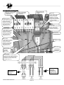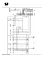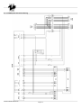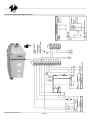
1
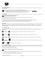
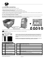
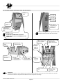
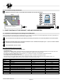
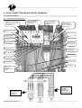
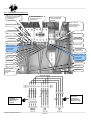
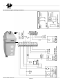
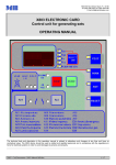
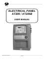
ELECTRICAL PANEL
AT206 / AT206B
USER MANUAL
Cod.Doc.2550041-REV02.doc
Pagina 25
INDEX:
1 - General ...........................................................................................................................................................................................................................27
1.1 - Introduction ...............................................................................................................................................................................................................27
1.2 - General warning........................................................................................................................................................................................................27
1.3 - Symbols in the manual .............................................................................................................................................................................................28
1.4 - Important tips ............................................................................................................................................................................................................29
1.5 - Cautions....................................................................................................................................................................................................................29
1.6 - Noise.........................................................................................................................................................................................................................29
1.7 - Cautions levels..........................................................................................................................................................................................................29
1.8 - Temporary Storage ...................................................................................................................................................................................................29
1.9 - Transporting..............................................................................................................................................................................................................30
1.10 - Overall size .............................................................................................................................................................................................................30
1.11 - Disposal ..................................................................................................................................................................................................................30
1.12 - Assistance center ...................................................................................................................................................................................................30
1.13 - Repairs and spare parts .........................................................................................................................................................................................30
1.14 - Guarantee conditions..............................................................................................................................................................................................30
1.15 - Ordering spare parts ...............................................................................................................................................................................................30
2- AT206 panel description ................................................................................................................................................................................................31
2.1 - How is the package and what is included.................................................................................................................................................................31
2.1.1 - Identification data plate ......................................................................................................................................................................................31
2.1.2 - Identification plate data specifics .......................................................................................................................................................................31
2.2 - Product external and internal view with description..................................................................................................................................................32
2.3 - Panel wall mounting instructions ..............................................................................................................................................................................33
3 - First starting of the product, use and description .....................................................................................................................................................33
3.1 - Operation to do during the first starting of the AT206 panel .....................................................................................................................................33
3.1.1 - How programming the time on the panel ...........................................................................................................................................................33
3.2 - AT206 panel; LED indication decription....................................................................................................................................................................34
3.3 - AT206 panel; command buttons decription ..............................................................................................................................................................34
3.4 - AT206 panel; function description ............................................................................................................................................................................35
3.4.1 - Procedure to setting tha automatic test..............................................................................................................................................................35
4 - AT206 connection and electrical drawings.................................................................................................................................................................36
4.1 - Power connection .....................................................................................................................................................................................................36
4.1.1 - Triphase connection 400Vac 3P+N....................................................................................................................................................................36
4.1.2 - Triphase connection 230Vac 3P+N....................................................................................................................................................................37
4.1.3 - Monophase connection 230Vac ........................................................................................................................................................................38
4.2 - AT206 panel electrical drawing.................................................................................................................................................................................39
4.3 - AT206B panel electrical drawing ..............................................................................................................................................................................40
4.4 - Diesel engine auxiliary connection ...........................................................................................................................................................................41
4.5 - Gasoline engine auxiliary connection .......................................................................................................................................................................42
5 - AT206 panel programmation instruction ....................................................................................................................................................................43
5.1 - Programmation menu access description.................................................................................................................................................................43
5.2 - Parameters modification instructions ........................................................................................................................................................................43
5.3 - User menu parameters .............................................................................................................................................................................................43
5.4 - Advanced menu parameters.....................................................................................................................................................................................44
6 - General sales conditions and warranty ......................................................................................................................................................................47
Cod.Doc.2550041-REV02.doc
Pagina 26
1 - GENERAL
The Instruction for Use are integral part of the machine and must accompany it for all its useful life until its demolition.
For every operation one must always apply to what is prescribed in the Instructions.
Follow scrupolously all indication reported in the Instructions
Prevent from making use of the machine operators not knowing the prescription based on the Instructions
Keep complete and legible Instructions in a place accessible to operators.
Hand over the manual to any other user or successive owner of the machine.
Verify if the registration number reproduced on the technical card of the acquired model agrees with that one cut with the label of the “Marking CE”
The Firm “TECNOELETTRA s.r.l.” will not think he is responsible for difficulties, breaks, accidents etc. due to the no knowledge or at any rate to the no
application of the rules held in this manual.
The same is told for the execution of changes and variants or for the installation of accessory not previously authorized.
1.1 - Introduction
Dear Customer,
We would like to thank you for your attention and for purchasing a “TECNOELETTRA” high-quality “Electric Panel.”
Our Technical Service and Spare Parts departments will do their utmost to help you should you need it.
To this regard, for all control and overhaul operations, please call “TECNOELETTRA” who will provide you with specialized, prompt action.
If you have had parts replaced, ask and make sure that only genuine “TECNOELETTRA” spare parts are used in order to assure you that the initial
performance and safety required by current standards are restored.
Use of non-genuine spare parts shall immediately forfeit all right to warranty and Technical Service by “TECNOELETTRA”.
The special composition and design of this panel enables satisfying the most restrictive operator safety standards.
To use “TECNOELETTRA Electric Panels” in the best way, below we give the most important rules to be followed.
1.2 - General warning
- This manual has been drawn up for the USER, the MAINTENANCE TECHNICIAN, the REPAIRS TECHNICIAN.
- Read this manual carefully since it server as a guide to the way the electric control board is designed to be used, to its technical features, to supply
the instructions for installation, assembly, regulation and use. It is also useful for personnel training, to indicate the maintenance operations, for
ordering spare parts and to give indications of the outstanding hazards.
- It is wise to remember that should any difficulty arise in its use, installation or whatever, our Technical Service is always at your disposal for any
explanations or action.
- The instruction manual should be considered as part of the equipment and must be "KEPT FOR FUTURE REFERENCE" as long as the equipment is
assembled.
- The manual must always be available for consultation near the electric control board and kept in a suitable manner (in protected, dry places, away
from direct sunlight, etc.).
- It should be borne in mind that some diagrams it contains have only the purpose of identifying the parts described and therefore might not correspond
to your machine.
- After opening the package, check the entire unit in case of problems with this unit do not use it until you have consulted an the Retailer or
Manufacturer otherwise all warranty rights will be voided.
Cod.Doc.2550041-REV02.doc
Pagina 27
- This electric panel has only to be used for the purpose for which it was specifically designed. Any other use shall be considered improper and,
therefore, dangerous.
- Our products are made in conformity with current safety standards so it is recommended to use all these devices and take care that their use causes
no injury or damage.
- All operations concerning the installation of the control panel should be carried out by skilled personnel in conformity with present regulations.
- During work it is recommended to keep to the current personal safety rules in force in the country the product is destined for (clothing, work tools,
etc.).
- When the unit is working do not use the electric control board parts.
- Never for any reason modify any part of the electric panel (connections, holes, electrical or mechanical devices, etc.) unless duly authorized to do so
in writing by “TECNOELETTRA”: the responsibility deriving from any such action shall fall on the person doing it since he then in fact becomes its
manufacturer.
- Before doing any cleaning or maintenance, de-energise and switch off the machine it is connected to.
- De-energise and disconnect the equipment in the event of breakdown or malfuncion. If any repairs is needed contact an Authorized Retailer only
and ask that only original spare parts are used. Failing to observe the above instructions may put the safety of the electric control board at risk
and the warranty will immediately decline.
- When installing the control panel comply with the IP protection seal indicated on the identification plate. If the IP protection seal is not indicated and
for different kinds of "IP" protections diverse contact one of our service centres or contact our technical office directly.
- Make sure that earthing complies with the standards in force in the country in which the appliance is used.
- Check that control panels that are installed on the machine are not subjected to vibrations that could damage the parts.
N.B.: The panel size depends on an ambient temperature of 35 degrees Centigrade.
- As a consequence, please make sure that these levels are complied with. As concerns atmospheric conditions, the prescriptions contained in the CEI
EN 60439-1 (6.1.2) have to be complied with.
- Check that the information on the control panel identification plate is compatible with appliance ratings such as voltage, current, frequency, etc.
- If the control panel can be locked, make sure that only authorised personnel can use the key to open the control panel.
- For the protection of inlet lines are not protected comply strictly with the regulations in force in the country in which the control panel is used.
- If the control panel is fitted with guards that need to be removed to wire up the control panel, make sure that they are refitted after the control panel
has been wired up. Make sure that the control panel is disconnected and locked out during these operations and that no parts carry residual current.
- Strictly follow the wiring diagram that accompanies the control panel.
- The manufacturer declines any responsability in to following cases:
a) misure of the machine or use by persons not trained for its operation.
b) incorrect installation.
c) operating faults machine is applied who to electric control board.
d) serious lack of due maintenance.
e) unauthorized modifications or servicing.
f) use of non-original or non-specific spare parts for the model.
g) total or pairtial failure to follow the instruction.
h) unforoseen events ect.
The instruction manual can never substitute a sufficiently experienced user.
The panels’ interruption power is 10 kA. For more powerful systems, please make sure that the right protection levels in the panel inlet lines are
supplied.
Warning: This booklet is not binding. “TECNOELETTRA” reserves the right, without prejudice to the essential features of the model herein
described and illustrated, to make improvements and modifications to parts and accessories without moreover undertaking to update this
manual in time.
1.3 - Symbols in the manual
The symbols contained in this manual have the purpose of drawing the user’s attention in order to prevent trouble or danger both for persons and
objects or the equipment.
These symbols moreover have the purpose of drawing your attention in order to indicate correct use and obtain good operation from your electric panel.
Cod.Doc.2550041-REV02.doc
Pagina 28
1.4 - Important tips
User tips on safety:
N.B. The information contained in this manual may be changed without notice.
Any damage caused in relation to the use of these instructions shall not be considered since they are only guidelines.
We remind you that failure to observe the instructions we give could cause injury or damage.
It is anyhow understood that current local regulations and/or laws must be observed.
1.5 - Cautions
Hazardous situations - safety for persons and objects.
USE ONLY WITH SAFE INSTALLATIONS
It is prohibited to fail to comply with, take away or put out of service the instructions, safety and supervision functions.
USE ONLY IN PERFECT TECHNICAL CONDITIONS
The electric panels must be used in perfect technical conditions. Any defects that may alter safety must immediately be eliminated.
Never install the electric panels close to sources of heat, in areas where there is a risk of explosion or fire hazard.
Where possible, repair the electric panels in a dry place far from water, protecting them against moisture.
1.6 - Noise
This appliance is in conformity with the provisions of EEC Directive 86/594 since the level of sound pressure is “irrelevant” (it is not perceptible by the
hearing of a human being) since its operation is given by the flow of energy passing through the control components and by the management of the
electric control panel.
1.7 - Cautions levels
Below we give the symbols used in the manual to draw the reader’s attention to the different levels of danger in the “Use and Maintenance” of the
electric panel.
DANGER!!
Information or procedures that, unless carried out meticulously, cause death or serious injury.
CAUTION!!
Information or procedures that, unless carried out meticulously, could cause death or serious injury.
PRUDENCE!!
Information or procedures that, unless carried out meticulously, could cause slight injury or damage to the electric
panel.
WARNING
and prevent damage.
NOTE
Information or procedures that advise the operator on the optimum use of the electric panel to extend its service life
Important information and procedures.
1.8 - Temporary Storage
In the case of temporary storage of the electric panel, before final installation it is necessary to take some precautions so as not to damage the external
structure and internal electric and electronic devices.
Store the electric panel packed in a closed, covered place.
Position it in a stable manner with no risk of it accidentally falling.
- Position the electric panel in a place protected against atmospheric agents with a humidity level between 30 and 75% and a temperature between 25° C and +55°C with short times not exceeding 24 hours, up to +70°C.
- Stack the electric panels without stacking too many one on top of another.
Cod.Doc.2550041-REV02.doc
Pagina 29
1.9 - Transporting
Transportation of the electric panel must be done so as not to jeopardize its structure.
On receiving the panel, inspect it for any damage suffered in transit and that the data given on the rating plate correspond to what you requested. Any
damage must be reported in writing to the carrier directly when the goods are received. Compensation for damage will be paid in accordance with
current legislation on carriage.
In the event of damage due to transportation or delivery of the wrong model, call the firm that carried out the service and “TECNOELETTRA”.
Before removing the packing from the electric panel, carefully read the user warnings given in this handbook.
All the packing material of the electric panel must be disposed of in accordance with current regulations.
1.10 - Overall size
The size of the control panels is suited to meet customer requirements and their dimensions are therefore shown on the "Technical Data" identification
plate.
1.11 - Disposal
After use or in the case of demolition, the appliance must be disposed of according to the legislative provisions in force in the country it is destined for.
CAUTION!
In addition, it is wise to destroy the machine’s identification plate and any other documents.
1.12 - Assistance center
All maintenance work and technical service must be performed by “Specialized personnel” authorized by “TECNOELETTRA” who will arrange for a
technician to step in after the customer’s call.
1.13 - Repairs and spare parts
For any further inconveniences, not mentioned in this booklet or any demages of the machine, we suggest you to go to the Retailer or Manufacturer
for the repair or possible replacement of any original spare parts.
When requesting spare parts, always:
- Quote serial number.
Identification abbreviation that is stamped onto the part.
Do not wait for the components to be worn out.
Replacing a component at the right moment means to improve the electric control board operation and at the same time avoid greater
damages.
1.14 - Guarantee conditions
See document n.5159 at the end of this section of the instruction manual
1.15 - Ordering spare parts
The spare parts orders must be accompanied with following indications:
- Serial number of the board.
- Letter/code stamped on the component to be replaced.
Due to the different types of product, it is not possible to enclose drawings of spare parts. They need to be requested with the serial number of the board
and the code of each single component.
Cod.Doc.2550041-REV02.doc
Pagina 30
2- AT206 PANEL DESCRIPTION
This product permit to control all the functions about a generator
•
•
•
•
Engine command and protection module for diesel or gasoline generators
Measurement system for main electric values
Automatic control module for two different supply sources (Automatic Mains Failure)
Automatic changeover switch from two different supply sources (Automatic Transfer Switch)
It’s builded to monitor monophase, triphase or triphase with neutral systems in alternate current; it permit to transfer the user’s load on generator when
the mains voltage is faulty. Voltage and current detection are monophase.
2.1 - How is the package and what is included
The packing must be completely closed and it must be in good conditions.
In the package, there is the panel but there are also a pocket with a couple of connectors for auxiliary connections (a), a couple of fixing hooks (b), a
couple of spare fuses (c), the instruction manual (d) and labels with alarms list in several languages (e).
Targa dati tecnici
Identification
data
plate
a
b
c
d
The identification plate data give all the informations about the product; you can found it on the package and on a side of the panel
WARNING: check if the product received is in accordance to the product ordered.
2.1.1 - Identification data plate
The technical plate is secured on the outside of the electric panel, it gives the main particulars and
certifies its conformity with the EEC machine directive 89/392 (attachment H). Therefore its CE
marking is valid only when mounted with machines made in accordance with the provisions of the
EEC machine directive 89/392 and subsequent amendments introduced 91/368 EEC, 83/44 EEC,
93/68 EEC.
Every time you need to carry out special maintenance, repairs or to request spare parts it is
necessary to call the Manufacturer or Dealer, always quote the serial number.
2.1.2 - Identification plate data specifics
In =
Nominal current
V=
Nominal voltage on power circuits
Imax. =
Maximum permitted current
Vaux =
Nominal voltage on auxiliary circuits
KA =
Maximum current that is safe from
short circuits
IP =
The protection seal is IP 20 for all the type of panel
Hz =
Nominal frequency
Kg =
Weight (only approximate and is subject to variation)
KVA =
Apparent power (calculated at a 0,8
cos)
Dim =
KW =
Active power
Ser.n =
Sizes (refer to dimensions of the box and do not consider any components whose
installation might modify base dimensions). The measurements are expressed as
"height x width x depth".
Indicate the serial number required to identify the product. This number must
always be quoted in requests for spare parts.
HP =
Horsepower (not important)
Model =
Indicates the code of the control panel that enables the type to be identified.
Cod.Doc.2550041-REV02.doc
Pagina 31
e
2.2 - Product external and internal view with description
Control
board
F1 = F4A
F2 = F2A
F3 = F2A
Buzzer “B”
for acoustic
alarm
“IMP” switch to
supply 230Vac for
auxiliary output.
(OPTIONAL)
Predisposition for
magnetothermic
switch or earth failure
relay.
ATTENTION: Change the fuses only with others of the
same type and with the same data current values
Emergency button
ATTENTION!!! IN EMERGENCY SITUATION,
PRESS THIS BUTTON TO STOP IMMEDIATLY THE
GENERATOR
Input for mains
power
connection
Input for
generator power
connection
Mains contactor
“TLR”“ and power
connection
Output for load
power connection
Automatic battery
charger: when it’s
supplied, the red led is
on
Generator
contactor
“TLG” and
power
connection
Auxiliary
connector “CN1”
Auxiliary
connector “CN2”
Earth
connection
fixing point
Current transformers
“TA”
Output terminals
for user’s power
connection
ATTENTION:
The panel in the picures is only an example and it’s one of the model in production; for this reason, the current transformers, the power
circuit and the contactors in the panel must be different from the components in the image.
Cod.Doc.2550041-REV02.doc
Pagina 32
2.3 - Panel wall mounting instructions
WARNING: THE INSTALLATION OF THE PANEL MUST BE MADE ONLY BY SKILLED PEOPLE
The panel must be fixed on the wall by
two fixing hook in equipment
.
For air flow reasons, it is necessary that
around the panel there is a free space of
about 10cm for all the perimeter
3 - FIRST STARTING OF THE PRODUCT, USE AND DESCRIPTION
3.1 - Operation to do during the first starting of the AT206 panel
When you supply for the first time the panel, the display shows “U11” flashing, to remember you the time programmation (User menu, parameter U11).
Press RESET button to stop this flashing and set the board in RESET position.
The non observance of the indications given about the first starting of the product, can cause faulty situations on the same product
Before the first starting of the panel, check that the indications on the “Identification data plate” (par. 2.1.1) are in accordance with the
characteristics of the present electrical system.
The programmation of time is needed
3.1.1 - How programming the time on the panel
To program the time, follow the procedure descripted below:
- Press RESET button
- With the board in RESET position, press TEST button for 5 seconds until the display shows “Set”; after that the display shows the first code of the
parameter “U.01 – Automatic test interval time”. To see all the parameters, please check the following table
- By continously pressing of MEAS button, reach parameter “U.11” showed on the display. This parameter is about the actual time.
- Press TEST button to see the value stored now.
- Press START button to increase the value of the hour or press STOP button to increase the value of the minutes
- When the time is correct, press RESET button to save it and press AUT button to return on the parameter code (the display shows U.11)
- Press AUT button than RESET button to exit from menu and return to the normal function mode.
Setup
Description
Range
Default
Group 1
U.01
U.02
U.03
U.04
Test
Automatic test interval time
Test duration
Test start time
Test with load
1 – 30days
1 – 30 min
00:00 – 23:59
0=with load 1=without load
3 days
10 min
10:00
1
Group2
U.08
U.09
U.10
Various
Siren relay closing time
Engine departure delay from EJP/T start
Switching delay for EJP/T(1 wire)
0 – 60 sec
0 – 99 min
0 – 30 min
20 sec
25 min
5 min
Group3
U.11
Clock setting
Time
00:00 – 23:59
11:11
Cod.Doc.2550041-REV02.doc
Pagina 33
3.2 - AT206 panel; LED indication decription
4 digit multifunction
display to show
measurement,
function and
alarms status
Type of
measurement
showed by the
display
If flashing, it indicate that the
engine is running and the
alarms are not enable. If on,
it indicate that the engine is
running and the alarms are
enable.
If on, it indicates that
the voltage measured
is about the mains
If on, it indicates that
the board is in
MANUAL (Par. 3.4)
If on, it indicates that
the voltage measured
is about the
generator
If on, it indicates that
the board is in
AUTOMATIC
(Par. 3.4)
If on, it
indicates that
the mains
voltage is ok
If on, indicates that
the mains contactor
is closed (the mains
supply the load)
If on, it
indicates that
the automatic
test is enable
(Par. 3.4)
If on, it indicates
that the board is in
RESET (Par. 3.4)
If on, it indicates that
the generator voltage
is ok
If on, indicates that the generator
contactor is closed (the generator
supply the load)
If on, it indicates that one or
more alarms are active
3.3 - AT206 panel; command buttons decription
It permit to start the generator
(enable only in MANUAL
function)
It permit to change the
type of measurement
showed by the display
It permit to activate
the automatic test
(Par. 3.4)
It permit to close
the mains
contactor (active
only in MANUAL
function; press it
with MAN button in
the same time)
Board in MANUAL
function (Par. 3.4)
Board in
AUTOMATIC function
(Par. 3.4)
It permit to close
the generator
contactor (active
only in MANUAL
function; press it
with MAN button in
the same time)
Board in RESET
(Par. 3.4)
It permit to stop the generator (enable only
in MANUAL function)
Cod.Doc.2550041-REV02.doc
Pagina 34
3.4 - AT206 panel; function description
BOARD IN RESET
The generator can’t work. If the mains is ok, the mains contactor is closed. If the generator is running, when you change to this function mode the
engine is stopped immediatly and the eventual alarms are resetted. The alarm can’t be resetted if the cause of alarm still remain.
BOARD IN MANUAL
The generator can be started and stopped only manually by START and STOP buttons; also the changeover switch function works from mains to
generator and viceversa by MAINS and GEN buttons.
BOARD IN AUTOMATIC
The generator start automatically when there is a mains failure and stop automatically when the mains is ok.
AUTOMATIC TEST
Is enable only if the board is in automatic function. If enable, make a complete starting procedure in accordance to the programmation set. If the mains
is ok, this test is without changeover switch on the generator contactor; if during this test there is a mains failure, automatically the board close the
generator contactor to supply the load by the generator. The stop procedure begin only when the mains come back to correct values.
ALARMS
When there is an alarm, the display shows an identification code about the problem: on the label of the boards there is a list with alarms code and
description. By RESET button you can reset the alarms and by this you prevent an involuntayr restart of the generator. If the alarm on the display
doesn’t disappear, you have to remove the cause of the alarm.
3.4.1 - Procedure to setting tha automatic test
It’s strongly reccomended the enabling of the automatic test to prevent problems caused by a long inactivity of the generator
To enable the automatic test, please follow the instruction below:
- Press RESET button
- With the board in RESET position, press TEST button for 5 seconds until the display shows “Set”; after that the display shows the first code of the
parameter “U.01 – Automatic test delay time”. To see all the parameters, please check the following table
- Press TEST button to see the value stored now, then press START button to increase this value or STOP button to decrease it. When the value is
correct, press RESET button to save the modification and press AUT to exit from parameter. This parameter specifies the delay from one automatic
test and the next one. If you don’t press RESET before exit by pressing AUT, modifications made on the parameter won’t be saved.
- By pressing MEAS button, go to parameter “U.02” showed on the display. Press TEST button to see the value stored now, then by START button
(increase) or STOP button (decrease) change the duration time of the automatic test. When the value is correct, press RESET then AUT button.
- By pressing MEAS button, go to parameter “U.03” showed on the display. Press TEST button to see the value stored now, then by START button
increase the hours value or by STOP button increase the minutes value to change the starting time of the automatic test. When the value is correct,
press RESET then AUT button.
- By pressing MEAS button, go to parameter “U.04” showed on the display. Press TEST button to see the value stored now, then by START button
(increase) or STOP button (decrease) it; change if you want the automatic test with changeover switch (set it to “0”) or without changeover switch (set
it to “1”). When the value is correct, press RESET then AUT button.
- At the end, press AUT then RESET button to exit from menu and to return to the normal operating mode.
When the automatic test parameters are set, you have to enable this test; with the board in automatic mode, keep pressed TEST untill the display
shows “On” and the test led turn ON. From this moment the board starts the counting of the time to make the first test. This test will begin after the set
days in parameter “U.01”, at the set time in parameter “U.03” and for a set duration in parameter “U.02”. To disable the automatic test, with the board in
AUT position keep pressed TEST button untill the display shows “Off” and the test led turn off.
EXAMPLE:
Setup
Group 1
U.01
U.02
U.03
U.04
Description
Test
Automatic test interval time
Test duration
Test start time
Test with load
Range
1 – 30days
1 – 30 min
00:00 – 23:59
0=load 1=a vuoto
Default
3 days
15 min
10:00
1
If you enable the automatic test with TEST button on Monday afternoon at 15.00, first test will start 3 days after (on Thursday) from 10.00 to 10.15.
Second test will start on next Sunday (3 more days later) always from 10.00 to 10.15
Cod.Doc.2550041-REV02.doc
Pagina 35
4 - AT206 CONNECTION AND ELECTRICAL DRAWINGS
4.1 - Power connection
4.1.1 - Triphase connection 400Vac 3P+N
Generator contactor TG1.
Terminals sequence:
T1-T2-T3-T4
Mains contactor TR1.
Terminals sequence:
T1-T2-T3-T4
Load connection X0.
Terminals sequence:
U-V-W-N
Phase 1 load: U
It pass through TA
before connection to
load terminal U
Generator neutral: T4
Phase 2 load: V
Generator phase 3: T3
Generator phase 2: T2
Phase 3 load: W
Generator phase 1: T1
Neutral load: N
Mains phase 1: T1
Amperemetric
Transformer TA
Mains phase 2: T2
Generator input
Mains phase 3: T3
Mains input
Mains neutral: T4
Load output
Common earth
connection
(Genarator, Mains,
Load)
Electrical drawing
WARNING ! !:
TA current
transformer is
mounted only in
AT206 panel type
WARNING ! !:
Magnetothermic
switch is an
optional.
Cod.Doc.2550041-REV02.doc
Pagina 36
4.1.2 - Triphase connection 230Vac 3P+N
Generator contactor TG1.
Terminals sequence:
T1-T2-T3-T4
Mains contactor TR1.
Terminals sequence:
T1-T2-T3-T4
Load connection X0.
Terminals sequence:
U-V-W-N
Phase 1 load: U
It pass through TA
before connection to
load terminal U
Generator neutral: T4
Generator phase 3: T3
Phase 2 load: V
Generator phase 2: T2
Phase 3 load: W
Generator phase 1: T1
Neutral load: N
Warning!! Move
blue wire n.24 from
terminal T4 to
terminal T3
Amperemetric
Transformer TA
Mains phase 1: T1
Warning!! Move
blue wire n.14 from
terminal T4 to
terminal T3
Mains phase 2: T2
Mains phase 3: T3
Generator input
Mains neutral: T4
Mains input
Common earth
connection
(Genarator, Mains,
Load)
Load output
Electrical drawing
WARNING ! !:
TA current
transformer is
mounted only in
AT206 panel type
WARNING ! !:
Magnetothermic
switch is an
optional.
Cod.Doc.2550041-REV02.doc
Pagina 37
4.1.3 - Monophase connection 230Vac
Generator contactor TG1.
Terminals sequence:
T1-T2-T3-T4
Load connection X0.
Terminals sequence:
U-V-W-N
Mains contactor TR1.
Terminals sequence:
T1-T2-T3-T4
Generator neutral:
to use maximum contactor
power, poles T3 and T4
must be connected
togheter; T3+T4=Neutral.
By this connection the
max current of the
contactor is Ith x 1,6
Load phase:
to use maximum terminals
power, poles U and V
must be connected
togheter; U+V=Phase.
These wires must pass
through the amperemetric
transformer before
connection to terminals U
and V
Load neutral:
to use maximum terminals
power, poles W and N
must be connected
togheter: W+N=Neutral.
Generator phase:
to use maximum contactor
power, poles T1 and T2
must be connected
togheter; T1+T2=phase.
By this connection the
max current of the
contactor is Ith x 1,6
Amperemetric
transformer TA
Mains phase:
to use maximum contactor
power, poles T1 and T2
must be connected
togheter: T1+T2=phase.
By this connection the
max current of the
contactor is Ith x 1,6
Generator input
Mains input
Common earth
connection
(Genarator,
Mains, Load)
Mains neutral:
to use maximum contactor power,
poles T3 and T4 must be connected
togheter: T3+T4=Neutral. By this
connection the max current of the
contactor is Ith x 1,6
Load output
Electrical drawing
WARNING ! !:
TA current
transformer is
mounted only in
AT206 panel type
WARNING ! !:
Magnetothermic
switch is an
optional.
Cod.Doc.2550041-REV02.doc
Pagina 38
4.2 - AT206 panel electrical drawing
Cod.Doc.2550041-REV02.doc
Pagina 39
4.3 - AT206B panel electrical drawing
Cod.Doc.2550041-REV02.doc
Pagina 40
4.4 - Diesel engine auxiliary connection
Cod.Doc.2550041-REV02.doc
Pagina 41
4.5 - Gasoline engine auxiliary connection
Cod.Doc.2550041-REV02.doc
Pagina 42
Cable connection and fixing power on contactor’s terminals and output terminals, must be in accordance to following data
Minimum and maximum terminals fixing power .Warning!!! During
Minimum and maximum section
Contactor (check the type
the power cables connection, don’t move the auxiliary wires from
of the cables connected without
installed in the panel)
the contactor terminals and check if they are properly fixed
terminals
togheter with power cables in the terminals.
Tipo
mm
Nm
Ibft
BF9T
1-6
1,5-1,8
1,1-1,5
BF12T
1-6
1,5-1,8
1,1-1,5
BF18T
1-6
1,5-1,8
1,1-1,5
BF26T
2,5-6
2,5-3
1,8-2,2
BF38T
2,5-16
2,5-3
1,8-2,2
CL04
2,5-16
1,4
1,02
WARNING !! If the installation of the product is not in accordance to the specifics descripted above, can cause problems in terms of
functionality and can also compromises warranty conditions. Then Tecnoelettra srl won’t be responsible for any direct or not direct
damage due to wrong installation.
Contactor Ith
thermal current
25A
32A
45A
56A
60A
POWER CONVERSION TABLE
Panel maximum power
Panel maximum power
400Vac 3P+N
230Vac 3P+N
kVA max / I max
kVA max / I max
17kVA
22kVA
31kVA
38kVA
42kVA
/
/
/
/
/
25A
32A
45A
56A
60A
10kVA
12kVA
18kVA
22kVA
24kVA
/
/
/
/
/
25A
32A
45A
56A
60A
Panel maximum power
230Vac 1P+N
kVA max / I max
9kVA / 40A
11kVA / 50A
16kVA / 72A
20kVA / 89,5A
22kVA / 96A
5 - AT206 PANEL PROGRAMMATION INSTRUCTION
5.1 - Programmation menu access description
With the board in RESET position, press TEST button for 5 seconds; after that, the entrance in the menu is showed by the display with the first code of
the parameter “U.01”.
This procedure permit to enter only in the “User menu”; that permits to modify only the normal use parameters (descripted in par. 5.3); by this you are
not able to enter in the technical parameters that can cause function problem in the panel (these parameters are descripted in par.5.4).
To have access to complete menu (advanced menu), you need a different password.
To have it, please contact the dealer or the manufacturer.
5.2 - Parameters modification instructions
TEST button permits to see the value of the parameter
START button permits to increase the value and STOP button permit to decrease the value. For the time setting, START button increase the hours
value and STOP button increase the minutes value.
To save the value set and exit from parameter, press RESET then AUT button. (In advanced menu only RESET button to save and exit)
To exit from parameter without saving, press AUT button.
MEAS button permits to change (increase) the number of the parameter in a menu
MAN button permits to change (increase) the number of the menu
At the end of the programmation, press AUT than RESET buttons to return definitively from programmation mode to operative mode.
5.3 - User menu parameters
Setup
Group 1
U.01
U.02
U.03
U.04
Group2
U.08
U.09
U.10
Group3
U.11
Description
Test
Automatic test interval time
Test duration
Test start time
Test with load
Various
Siren relay closing time
Engine starting delay from EJP/T signal
Switching delay for EJP/T(1 wire)
Clock setting
Time
Range
Default
1 – 30days
1 – 30 min
00:00 – 23:59
0=with load 1=without load
3 days
10 min
10:00
1
0 – 60 sec
0 – 99 min
0 – 30 min
20 sec
25 min
5 min
00:00 – 23:59
11:11
Cod.Doc.2550041-REV02.doc
Pagina 43
5.4 - Advanced menu parameters
Setup
Group 1
P1.01
.02
.03
Group 2
P2.01
Description
Panel nominal data
Nominal frequence
Current Trasformer ratio
(CT 100/5 = 20)
System (220V monophase, 220V triphase, 380V triphase)
Engine start-up
500 rpm signal from alternator or gen. (started engine)
Range
50Hz= 0 60Hz=1
1…2000
0=220M 1=220T
2=380T
Default
0
20
0
.02
.03
.04
.05
.06
.07
.08
.09
Started engine alternator batterycharger voltage threshold
Started engine generator voltage threshold
Starting with power failure
Preheating time
Number of starting attempts
Duration of starting attempts
Pause time within starting attempts
Automatic test enabling with remote stop signal presence
.10
.11
.12
Alarm enabling delay at starting (oil/V/freq.)
Air time
Air switch-off threshold
0= from alternator Vac
1= permanent magnet alt. (saprisa)
2= pre-excited alternator (D+)
3-30V
20-500V
On=1
Off=0
1-60 sec
1-10
1-30sec
1-20sec
0= start not enable
1= start enable
1-60sec
0-240 sec
30-255V
Group 3
P3.01
.02
.03
Motor stop
Stop times (electromagnet closing time / gasoline engine stop time)
Decelerated funct. time
Cooling time
1-30sec
1-60 sec
1 – 300sec
10
30
120
Group 4
P4.01
.02
.03
.04
.05
.06
.07
.08
.09
Protections
Minimum frequency (fixed delay 5sec)
Maximum frequency (overspeed)
Maximum frequency al. tripping delay
Battery minimum frequency
Battery maximum frequency
Load maximum current
Maximum current delay
Tripping delay of “500rpm failure” (strap breaking)
“Mechanical failure” tripping delay
80 – 100 %
100 – 120%
0-15 sec
7-12V
13 – 17V
10 – 2550A
0 – 600sec
0 –10 sec
0 - 10 sec
90%
110%
2 sec
9
17V
100A
10
5
5
Group 5
P5.01
P5.02
P5.03
Various
Generator and network contactor closing delay
Remote start input function
Re-commutation lock on network in case of alarm during EJP/T
P5.04
Hourcounter value
Group 6
P6.01
Programmable outputs
Programmable relay (terminal 63)
P6.02
Programmable relay (terminal 53 - 54)
0= alarm
1= decelerator
2= electromagnet or gasoline stop
0= alarm
P6.03
Programmable relay (terminal 62)
0= siren
1= alarm
0= siren
Range
0,1 –5 sec
0= normal
1 = on
0 = off
0 – 999.999
1= ejp/t
0= choke / air
1= glow plugs
2= alarm
3= fuel electrovalve
Note : Range P7.01, P7.02, P8.01 E P8.02 must always set in reference to 230V also if P1.03 =1 or P1.03=2
Cod.Doc.2550041-REV02.doc
Pagina 44
0
10
50
1
7
6
5
10
1
8
5
100
Default
1
0
0
0
1= glow plugs
Group 7
P7.01
.02
.03
.04
Network parameters
Mains voltage minimum threshold (measured)
Mains voltage maximum threshold (measured)
Mains voltage time out of the limits
Mains voltage return time within the limits
160 – 230Vac
200 – 345Vac
5 – 9999 sec
5 – 9999 sec
195Vac
260Vac
5 sec
10 sec
Group 8
P8.01
.02
.03
.04
Generator parameters
Generator voltage minimum threshold (measured)
Generator voltage maximum threshold (measured)
Generator voltage delay out of the limits
Generator voltage time within the limits
160 – 230Vac
200 – 345Vac
5 – 9999 sec
5 – 9999 sec
195Vac
260Vac
5 sec
20 sec
Alarms
Setup
Description
Range
0000=no 0001=yes
Default
A1
A1.01
A1.02
A1.03
A1.04
A1.05
Engine overtemperature
Stop without cooling
Stop with cooling
Siren relay
Alarm relay (if enabled see P6.02)
Not used
0000 / 0001
0000 / 0001
0000 / 0001
0000 / 0001
0000 / 0001
0000 / 0001
0001 = yes
0001 = yes
0000 = no
0001 = yes
0001 = yes
0000 = no
A2
A2.01
A2.02
A2.03
A2.04
A2.05
Oil low pressure
Stop without cooling
Stop with cooling
Siren relay
Alarm relay (if enabled)
Not used
0000 / 0001
0000 / 0001
0000 / 0001
0000 / 0001
0000 / 0001
0000 / 0001
0001 = yes
0001 = yes
0000 = no
0001 = yes
0001 = yes
0000 = no
A3
A3.01
A3.02
A3.03
A3.04
A3.05
Avaria meccanica
Stop without cooling
Stop with cooling
Siren relay
Alarm relay (if enabled)
Not used
0000 / 0001
0000 / 0001
0000 / 0001
0000 / 0001
0000 / 0001
0000 / 0001
0001 = yes
0001 = yes
0000 = no
0001 = yes
0001 = yes
0000 = no
A4
A4.01
A4.02
A4.03
A4.04
A4.05
500 rpm failure (strap breaking)
Stop without cooling
Stop with cooling
Siren relay
Alarm relay (if enabled)
Not used
0000 / 0001
0000 / 0001
0000 / 0001
0000 / 0001
0000 / 0001
0000 / 0001
0001 = yes
0000 = no
0000 = no
0001 = yes
0001 = yes
0000 = no
A5
A5.01
A5.02
A5.03
A5.04
A5.05
Overspeed (maximum frequency)
Stop without cooling
Stop with cooling
Siren relay
Alarm relay (if enabled)
Not used
0000 / 0001
0000 / 0001
0000 / 0001
0000 / 0001
0000 / 0001
0000 / 0001
0001 = yes
0001 = yes
0000 = no
0001 = yes
0001 = yes
0000 = no
A6
A6.01
A6.02
A6.03
A6.04
A6.05
Minimum frequency (fixed delay 5sec)
Stop without cooling
Stop with cooling
Siren relay
Alarm relay (if enabled)
Not used
0000 / 0001
0000 / 0001
0000 / 0001
0000 / 0001
0000 / 0001
0000 / 0001
0001 = yes
0000 = no
0001 = yes
0001 = yes
0001 = yes
0000 = no
A7
A7.01
A7.02
A7.03
A7.04
A7.05
Generator minimum voltage
Stop without cooling
Stop with cooling
Siren relay
Alarm relay (if enabled)
Not used
0000 / 0001
0000 / 0001
0000 / 0001
0000 / 0001
0000 / 0001
0000 / 0001
0001 = yes
0001 = yes
0000 = no
0001 = yes
0001 = yes
0000 = no
Cod.Doc.2550041-REV02.doc
Pagina 45
A8
A8.01
A8.02
A8.03
A8.04
A8.05
Generator maximum voltage
Stop without cooling
Stop with cooling
Siren relay
Alarm relay (if enabled)
Not used
0000 / 0001
0000 / 0001
0000 / 0001
0000 / 0001
0000 / 0001
0000 / 0001
0001 = yes
0000 = no
0001 = yes
0001 = yes
0001 = yes
0000 = no
A9
A9.01
A9.02
A9.03
A9.04
A9.05
Fuel
Stop without cooling
Stop with cooling
Siren relay
Alarm relay (if enabled)
Not used
0000 / 0001
0000 / 0001
0000 / 0001
0000 / 0001
0000 / 0001
0000 / 0001
0001 = yes
0000 = no
0000 = no
0001 = yes
0001 = yes
0000 = no
A10
A10.01
A10.02
A10.03
A10.04
A10.05
Maximum current
Stop without cooling
Stop with cooling
Siren relay
Alarm relay (if enabled)
Not used
0000 / 0001
0000 / 0001
0000 / 0001
0000 / 0001
0000 / 0001
0000 / 0001
0001 = yes
0000 = no
0001 = yes
0001 = yes
0001 = yes
0000 = no
A11
A11.01
A11.02
A11.03
A11.04
A11.05
Battery minimum voltage
Stop without cooling
Stop with cooling
Siren relay
Alarm relay (if enabled)
Not used
0000 / 0001
0000 / 0001
0000 / 0001
0000 / 0001
0000 / 0001
0000 / 0001
0001 = yes
0000 = no
0000 = no
0001 = yes
0001 = yes
0000 = no
A12
A12.01
A12.02
A12.03
A12.04
A12.05
Battery maximum voltage
Stop without cooling
Stop with cooling
Siren relay
Alarm relay (if enabled)
Not used
0000 / 0001
0000 / 0001
0000 / 0001
0000 / 0001
0000 / 0001
0000 / 0001
0001 = yes
0000 = no
0001 = yes
0001 = yes
0001 = yes
0000 = no
A13
A13.01
A13.02
A13.03
A13.04
A13.05
Starting failure
Stop without cooling (not influential, always as set to “no”)
Stop with cooling (not influential, always as set to “no”)
Siren relay
Alarm relay (if enabled)
Not used
0000 / 0001
0000 / 0001
0000 / 0001
0000 / 0001
0000 / 0001
0000 / 0001
0001 = yes
0000 = no
0000 = no
0001 = yes
0001 = yes
0000 = no
E1
E1.01
E1.02
E1.03
E1.04
E1.05
Remote stop
Stop without cooling (not influential, always as set to “yes”)
Stop with cooling (not influential, always as set to “no”)
Siren relay
Alarm relay (if enabled)
Not used
0000 / 0001
0000 / 0001
0000 / 0001
0000 / 0001
0000 / 0001
0000 / 0001
0001 = yes
0001 = yes
0000 = no
0001 = yes
0001 = yes
0000 = no
E2
E2.01
E2.02
E2.03
E2.04
E2.05
Emergency stop (not influential, always as set to “yes”)
Stop without cooling (not influential, always as set to “yes”)
Stop with cooling (not influential, always as set to “no”)
Siren relay
Alarm relay (if enabled)
Not used
0000 / 0001
0000 / 0001
0000 / 0001
0000 / 0001
0000 / 0001
0000 / 0001
0001 = yes
0001 = yes
0000 = no
0001 = yes
0001 = yes
0000 = no
Cod.Doc.2550041-REV02.doc
Pagina 46
6 - GENERAL SALES CONDITIONS AND WARRANTY
PRICES
The prices are those specifically valid of the ruling price list, VAT excluded. Furthermore, they do not cover the costs of packing, carriage, delivery,
custom duties and/or any other charges, unless stated otherwise. Except when agreed with TECNOELETTRA in writing, the ruling prices shall be
applied to all deliveries beginning from January 1. Furthermore, the prices are not binding and for general guidance only: the Seller shall have the right
to increase or decrease prices for eventual variations occurring in the cost of raw materials.
MODIFICATIONS TO PRODUCTS
The Seller reserves the right and the faculty, without previous warning, to make any modification for improvement of the products, including constructive
ones without however altering the overall structure or dimensions but assuring a total interchangeability at all times.
SUPPLY
The terms of the contract only include what is clearly and specifically described in the Seller's order. At any moment, the contract shall be suspended in
case the Buyer's property conditions change as per the Italian Civil Code art.1461. Performance of the contract by the Seller is subject to availability of
goods and material from time to time.
DELIVERY
Unless otherwise agreed in writing, as a general rule, delivery shall be ex works Guastalla. All responsibility on the Seller's part shall cease when the
goods subject of the contract are despatched from the Seller's premises; goods are consequently transported at the risk and danger of the Buyer.
DELIVERY TIMES
The delivery times defined in the Seller's quotations and in any other document issued by the Seller, begin from the date of receipt of the Buyer's order
and are an estimate only.
The Seller's reserves the right to extend the delivery time whenever the Buyer delays to fulfil the contract obligations and in particular if:
there is a breach of payment;
the Buyer does not provide each necessary data on time or does not promptly communicate his approval for drawings or schematic diagrams,
whenever requested;
the Buyer requires modifications during the contract period;
the Buyer does not supply the materials of his supply on time
circumstance beyond the Seller's control; which circumstances shall include but not be limited to weather conditions, fire, breakdown in the
Seller's plant or machinery, floods, earthquakes, war;
immobilisation requisitions, embargo, insurrection, shortage or breakdown of transport materials or plant, restrictions on the use of power,
lockout, strike, stoppages, industrial disputes or acts of terrorism, etc.
DELIVERY DELAYS
Eventual delivery delays do not give the Buyer the right to cancel the contract, totally or partially, and to receive damages, except when regularly
stipulated in the contract.
PACKING
It is always gratis.
WARRANTY AND GUARANTEE
The Seller guarantees that the products the subject of the contract shall be free from defects including components and manufacture and specifications
of the contract. The warranty period is 12 months from the date the goods the subject of the contract are despatched from the Seller's premises.
The warranty is applicable to the products supplied by the Seller and includes parts and components purchased from other suppliers of the Seller.
The guarantee does not cover:
parts subject to normal wear
parts damaged for improper usage
parts damaged for inattentive and/or careless treatment
parts damaged for improper assembly
parts damaged for excessive stress imposed to materials
parts damaged for negligence in the maintenance operations
parts damaged for circumstances not subject to the Seller's control.
The Seller shall replace or repair all products or components which present proven manufacture defects on condition that they are claimed for in writing
within the validity of the warranty period. Each repaired or replaced item is guaranteed for a period as the previous one.
The Buyer has no right to claim for damage or loss whatsoever kind arrising out of the provision or performance. The guarantee is subject to the respect
by the Buyer of the contract obligations, with particular respect of the terms of payment.
PAYMENT
The payment of the Seller's invoice must be made in the form expressly specified in the contract.
The Buyer's takes upon himself all risks involved in the transfer of the sums, whichever the method used.
For the amounts which will not be received at the payment due date, the current bank interest of the Seller shall be applied.
Payment will not be witheld pending the settlement of eventual technical or commercial objections raised.
Eventual payment breaches give the Seller the right to suspend the outstanding contracts or to require their payment in advance.
RETURN OF MATERIALS
The return of goods shall not be accepted unless previously agreed and authorized in a writing.
The acceptance of returned materials for causes not due to the Seller, depends only on the Seller's unquestionable discretion and at the conditions
given herebelow:
standard material normally on stock
original packing
no visible damage
indication of the purchase date, if possible, on the return documents
validity of the product warranty
20% deduction for handling charges, VAT excluded
return of material free of charge
PROPER LAW
For any dispute, the only competent court shall be Reggio Emilia. Whenever the Buyer intends to apply a penalty, it is to be notified by registered letter.
Retroactive effect to the date of letter receipt is not accepted. For all legal proceedings, our registered office at Via Dimo Vioni 5, Guastalla, Reggio
Emilia, Italy is valid.
The proper law governing each contract is the Law of Italy.
Conditions mentioned above cancel and substitue all previous ones.
Cod.Doc.2550041-REV02.doc
Pagina 47
Cod.Doc.2550041-REV02.doc
Pagina 48