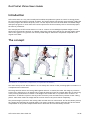
1
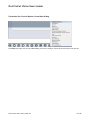
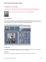
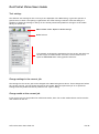
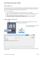
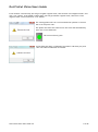
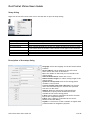
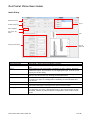
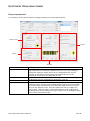
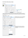
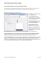
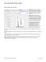
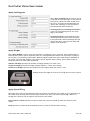
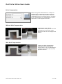
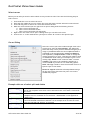
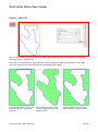
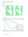
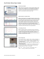
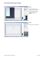
Océ ProCut
Vision Software
User Manual
Océ ProCut Vision is a user-friendly and advanced production system to control the Océ ProCut Digital Cutting
Table to enable accurate and fast cutting of a variety of shapes on a wide range of materials.
This user manual will introduce you the many features and procedures that will enable you to cut typical display
graphics jobs. It will guide you through how to install Océ ProCut Vision software, operate the system and use the
media library to streamline your workflow.
For further information on documentation and support, contact your local Océ representative.
Océ ProCut Vision Users Guide
Introduction
Océ ProCut Vision is a very user-friendly and an advanced production system to control a cutting plotter
for precise and fast cutting of all kind of shapes. Océ ProCut Vision will typically get production ready files
from the program Océ ProCut Prepress, but it can also import files from all other kind of standard design
and layout programs. In such cases Océ ProCut Prepress has all the necessary tools to check and prepare
the files for production.
The main purpose of Océ ProCut Vision is to trim or contour cut around digital printed images on both
sheets and roll material. With use of a digital camera the system will read the pre-printed register marks
and cut the graphics very precise even if the printed image is distorted or misplaced compared to the
original curve data.
The concept
A
B
C
(A no distortion, no misplacement, B misplacement, C misplacement and distortion)
The main concept of Océ ProCut Vision is to cut exactly the contour of the printed graphics no matter if it
is misplaced and/or distorted.
The image and the outline are fitting 100% together when it is created, but after the image is printed in
Screen Print, Offset Print or in Digital Print it might be distorted from the original shape due to inaccuracy
in the printing method and/or stretch or shrinkage of the media after it is printed. Even if there is no
distortion it is difficult to place it exactly at the reference point and without any rotation at the cutting
plotter. With other words the image and the contour does not any more match completely.
The printed image is placed on the cutting table and with the bar code scanner Océ ProCut Vision picks up
the cutting files matching the printed image. The camera reads the register marks and Océ ProCut Vision
compensates for any kind of misplacement and/or distortion and cuts extremely accurate.
Océ ProCut Vision User Guide 3.2
1 of 42
Océ ProCut Vision Users Guide
Table of contents
1. General operation of Océ ProCut Vision
Main Dialog --------------------------------------------------------------------------------Production modes ------------------------------------------------------------------------Control buttons (default) ---------------------------------------------------------------Control buttons (optional) --------------------------------------------------------------Customize the Control buttons ---------------------------------------------------------Configuration of the Tool Head --------------------------------------------------------Tool Configurator ------------------------------------------------------------------------Change tools ------------------------------------------------------------------------------Tool settings ------------------------------------------------------------------------------Change settings in the current job ----------------------------------------------------Change media at the current job ------------------------------------------------------Use of the command dialog in the Main Dialog --------------------------------------Show tool head or camera image in the Main Dialog -------------------------------Camera Calibration ----------------------------------------------------------------------Camera Calibration step by step ------------------------------------------------------Setup Dialog ------------------------------------------------------------------------------Description of the setup dialog --------------------------------------------------------Customize the twelve function keys at the computer keyboard -----------------Customize the control buttons in the Main Dialog ------------------------------Production Queue ------------------------------------------------------------------------Reproduce previous jobs ----------------------------------------------------------------Manage the production queue -----------------------------------------------------------
4
4
5
5
6
7
7
7
8
8
8
9
9
10
10
12
12
13
13
14
14
14
2. Media
The purpose of the media ---------------------------------------------------------------Media Library ------------------------------------------------------------------------------Cut Media Manager -----------------------------------------------------------------------Media Dialog -------------------------------------------------------------------------------Prepress Parameters ---------------------------------------------------------------------Select color for Register mark- and Barcode Background --------------------------Edit Media ----------------------------------------------------------------------------------Adding a layer to a media ---------------------------------------------------------------Assign a tool to a layer ------------------------------------------------------------------Setting cutting depth, speed etc. ------------------------------------------------------Going through different tool and media specifications -----------------------------Registration Marks Layer (Camera Tool) ----------------------------------------------Kiss Cut Layer (Kiss Cut Tool) -----------------------------------------------------------Through Cut Layer (Drag Knife Tool) --------------------------------------------------Through Cut Layer (Driven Rotary Tool) ----------------------------------------------Through Cut Layer (Router Tool) ------------------------------------------------------Apply Finishing Pass ---------------------------------------------------------------------Apply Bridges -----------------------------------------------------------------------------Apply Special Entry ----------------------------------------------------------------------Knife Compensation ----------------------------------------------------------------------
Océ ProCut Vision User Guide 3.2
15
15
16
17
18
19
20
20
21
21
22
22
23
24
24
25
26
26
26
27
2 of 42
Océ ProCut Vision Users Guide
3. Prepare jobs for production
Edit Job ------------------------------------------------------------------------------------Edit Dialog ---------------------------------------------------------------------------------Select Curves ------------------------------------------------------------------------------Curves Dialog ------------------------------------------------------------------------------Examples with use of select, split and delete ---------------------------------------Edit Toolbar -------------------------------------------------------------------------------Engrave Hatch Fill ------------------------------------------------------------------------Show ruler ---------------------------------------------------------------------------------Offset Curve -------------------------------------------------------------------------------Scale ----------------------------------------------------------------------------------------Merge ---------------------------------------------------------------------------------------File needs editing --------------------------------------------------------------------------
28
29
30
30
30
31
32
33
33
34
34
35
4. Production
Production step by step ------------------------------------------------------------------ 36
Start Océ ProCut Vision -------------------------------------------------------------------------------Load the first job -------------------------------------------------------------------------- 36
Check before cutting ---------------------------------------------------------------------- 36
Adjust the vacuum width ----------------------------------------------------------------- 36
Check the job queue ---------------------------------------------------------------------- 37
Help find the first register marks ------------------------------------------------------- 37
The cutting will start --------------------------------------------------------------------- 37
Load and prepare jobs while cutting -------------------------------------------------- 37
Use of Step & Repeat --------------------------------------------------------------------- 38
Result of Step & Repeat ------------------------------------------------------------------ 38
Manage the job queue while cutting --------------------------------------------------- 38
36
5. Advanced productions
Cutting and registration from the unprinted side -----------------------------------Produce single copies of a job from the unprinted side ----------------------------Produce multiple copies of a job from the unprinted side -------------------------Edge registration dialogs ----------------------------------------------------------------Edge registration without the use of register mark circles -------------------------
Océ ProCut Vision User Guide 3.2
39
39
39
40
41
3 of 42
Océ ProCut Vision Users Guide
1. General operation of Océ ProCut Vision
Main Dialog
In the main dialog you find a schematic of the actual cutting plotter. From this dialog it is possible to load
jobs, check and prepare them for production. The main dialog will help the operator of the cutting plotter
to plan and run the production in the most efficient way and it will help the operator to select the right
cutting tools and settings in order to avoid errors and waste of materials. While the production of the
current job is running it is possible to load, check and prepare the following jobs and save them in the job
queue in order to keep the cutting plotter running continuously.
Edit and Save media.
Open Cut Media
Manager
Media selector
Tool parking position
Specifications for
the selected media.
Vacuum
Adjustment
Actual tool head
configuration.
Info
Control buttons
Actual job
Stop, Run and Pause buttons
Dimensions
Production Mode selector
Production Modes
Production modes can easily be selected from the Main dialog. These three modes are standard shown
with regular graphic jobs on a conveyor equipped cutter.
The drop-down menu lists the possible production modes that a user has for a certain job with the
available hardware. The modes are automatically changing depending if a job has data in the register
mark layer, if the media is enabled for backside operations, if the cutter has conveyor transport, board
loading feature etc.
Océ ProCut Vision User Guide 3.2
4 of 42
Océ ProCut Vision Users Guide
Control buttons (default)
The control buttons in the Main Dialog is default defined in the following sequence for Screens 4:3
resolutions and with the following functionality. The dialog is limited to six enabled control buttons out of
thirteen possible buttons.
Open / Import files via barcode
Open / Import (.ai, .cut, .pdf, .dxf, .eps, .ps, .hpgl, .gdc) files
Edit the current job
Set copies dialog
Rotate job 90 degrees clockwise
Switch vacuum on/off
Control buttons (optional)
The following control buttons is default disabled from the Main Dialog and can be activated instead of the
active control buttons shown above. On Screens 16:9 resolution it is possible to have up to ten active
control buttons shown. The number of buttons shown is controlled from Setup, R-Keys Dialog.
Feed backwards feeds the media one page (plotter length) backwards
Feed forward feeds the media one page (plotter length) forward
Rotate job 90 degrees counter clockwise
Blow back activates air blowing in order to release the media (only PN-Line plotters)
Set reference start position
Clear reference start position (and go to machine start position)
Move to reference start position
Océ ProCut Vision User Guide 3.2
5 of 42
Océ ProCut Vision Users Guide
Customize the Control buttons from Main dialog
Hold Shift and right click at the Control Key you want to change. Select the new function from the list.
Océ ProCut Vision User Guide 3.2
6 of 42
Océ ProCut Vision Users Guide
Configuration of the Tool Head
Configuration of tool head is only necessary with all the PN-Line plotters and for the G3 plotters with
firmware version 1.40.1 or older versions. In later versions the configuration is done automatically.
Click at the Tool Head in the Main menu to enter the tool configurator.
Tool Configurator
In the top of the dialog you find the possible heads (PN-Line) and modules (G3). With the G3 line you only
find one head with a camera and three tool holders. In the left side of the dialog you see the actual tool
head configuration, in this case mounted with Kiss-Cut, EOT and Router tools.
In the right side you see the different tools available.
Change tools
Click at the tool from Possible Tools and then click at the tool holder where you like the selected tool to
be placed. Click OK to exit the dialog with the new tool configuration.
Important
Make sure that this configuration matches the actual tools mounted at the cutting plotter.
Océ ProCut Vision User Guide 3.2
7 of 42
Océ ProCut Vision Users Guide
Tool settings
The different tool settings for the current job are displayed in the Main Dialog. It gives the operator a
good chance to check if everything is right before the actual cutting is started. From this dialog it is
possible to change the settings on the fly for the actual job and also possible to change it in the media
library for future use.
Edit and Save media. Open Cut Media Manager
Media Selector
This example is showing the parameters for the current job which is a
10 mm Acrylic cut with a Router Tool with a 3 mm router bit at a
speed of 50000 RPM and a routing speed of 60 mm/s.
Change settings in the current job.
The settings for the current job can be changed at the Main Dialog shown above. These changes will affect
the current job only, not the general settings for the media. When this particular job is re-opened all
settings from last production will be present in the “layers” dialog.
Change media at the current job.
If the current job is to be produced on a different media, then click at the media selector and choose the
new media from the list.
Océ ProCut Vision User Guide 3.2
8 of 42
Océ ProCut Vision Users Guide
Use of the command dialog in the Main Dialog
Activate the Command Dialog with a right click in the work area of the main dialog.
Function
Open File
Move to position
Open File using Barcode
Edit Job
Copies
Start Cutting
Set Vacuum Width
Reference Point
Park
Emulator Setup
Edit Language
Description
Imports AI, Cut, PDF, DXF, EPS, PS, HPGL and GDC files
Displays the actual tool position and allow you to enter coordinates for a
new position
Import files/jobs identified by barcode
Opens the current job in the editor dialog
Enter number of copies in the Step & Repeat dialog
Starts cutting plotter when Online
The vacuum width will be set to position of the pointer
Setting and resetting the reference point at the cutting plotter
Setting the park position of the cutting plotter to the position of the pointer
Only available with a service key. Used for setup of the cutting plotter
emulator
Only available with a service key. Used for text customizing
Show tool head or camera in the main menu
In the right hand corner of the main dialog you see either the actual tool head or the camera image
Right click at the tool head to activate dialog where you can change between tool
head and camera.
Océ ProCut Vision User Guide 3.2
9 of 42
Océ ProCut Vision Users Guide
Camera Calibration
Camera Calibration is a function to enter the distance x and y between tool position 1 (the reference) and
the camera. The calibration is done by the technician first time the system is configured. After this you
only need to calibrate if you realize an inaccuracy in the registration.
The process is the following:
1. Place a piece of media (usually paper or self adhesive vinyl) at the cutting table
2. Move tool 1 (usually a Through Cut or Kiss Cut knife) to a position at the media where you want to
cut
3. By activating Camera Calibration the cutting plotter will cut an 8 mm circle in the media
4. The operator are asked to remove the circle and press “ok”
5. The plotter will move the camera in position, automatically enter the correct distances.
Camera Calibration step by step
Tool position 1
Right click at the tool head in the Main Dialog and select “Show
Camera” to open the next dialog.
Select “Calibrate Camera” to open the
Camera Calibration Dialog
Select the layer in correspondence with the tool mounted in position 1 (in this case Kiss Cut)
Place the media at the cutting table and move the laser pointer (manually from the keyboard) in position
to cut the circle.
Océ ProCut Vision User Guide 3.2
10 of 42
Océ ProCut Vision Users Guide
If the media is coloured vinyl you will get a lighter register mark, then activate “Find negative mark” and
click “Cut” button. If the media is white paper you will get a darker register mark, then leave “Find
negative mark” inactive and click “Cut” button.
The cutting plotter will cut a circle and ask the operator to remove
the circle and press “OK”
The plotter will move the camera over the circle and automatically
enter the correct distances.
The circle will turn green
A new dialog will show “Calibration Successful” and when you press
“OK” the Camera Calibration is finished.
Océ ProCut Vision User Guide 3.2
11 of 42
Océ ProCut Vision Users Guide
Setup dialog
Right click at the Océ ProCut Vision icon in the task bar to open the setup dialog
Function
Show Dialog
Help
About
Set Control Word
Load
Setup
Exit
Description
Opens the Main Dialog
Opens the Océ ProCut Vision User Guide
Opens a dialog showing the version number and dongle ID
Opens a dialog showing the current key number and give you access to enter
a new control word to activate a new version or new rights for the software
Imports AI, Cut, PDF, DXF, EPS, PS, HPGL and GDC files
Opens the setup dialog for system setup
Exits the Océ ProCut Vision software
Description of the setup dialog
Language: Select the language for the Océ ProCut Vision
software
Server Address: The IP address for the Océ ProCut
Vision Server this client is attached to
Port: The number of the serial port connected to the
cutting plotter
Units of Measurement: Select mm or inch
Reduce Plotter Length: To reduce cutting length of the
cutting plotter.
System is Conveyorised Active if the cutting plotter
includes a conveyor belt
Turn off vacuum motor after idle time. The vacuum
motor will automatically turn off after the specified
time (sec) in idle mode
Heads & Tools are used by the technician during
installation to specify which heads and tools are
available at the actual cutting plotter
F-Keys open a dialog to customize the twelve function
keys at the computer keyboard
R-Keys open a dialog to customize the six control
buttons in the Main Dialog
Logfiles is a function to create a number of logfiles with
production data for diagnostic purposes.
Océ ProCut Vision User Guide 3.2
12 of 42
Océ ProCut Vision Users Guide
Customize the twelve Short-Cut Function Keys at the computer keyboard
Open the F-Keys dialog in the Setup Dialog. Select the function you want for each of the twelve keys in
the list of functions for the actual key.
Customize the control buttons in the Main Dialog
Open the R-keys dialog in the Setup Dialog. Select the function you want for each of the six to ten buttons
in the list of functions for the actual button.
Océ ProCut Vision User Guide 3.2
13 of 42
Océ ProCut Vision Users Guide
Production Queue
The job queue is giving the operator of the cutting plotter the possibility to check and prepare jobs while
the plotter is running. The purpose of this is to be prepared before the plotter finishes the current job in
order to keep it running all the time to keep the throughput as high as possible. The job queue contains a
number of the latest jobs that are cut, the current job, and a number of new jobs ready for production.
Right click at the run button in the Main Dialog to open the Production Queue dialog. In this case the
“Auto Load Next Job” is active which means that it will automatically load the next job from this queue
when the current job is finished.
Recent produced jobs
Current job in production
Production Queue with jobs ready for production
Reproduce previous jobs.
With the pointer at “Old Jobs” you will see the list
of the latest produced jobs, from where you can
choose and move the job back to the production
queue in case you need to reproduce it.
Manage the production queue
With the pointer at a job in the Production Queue
you get a dialog with the possibilities to Load,
Edit, Remove or Move the jobs within the queue.
Océ ProCut Vision User Guide 3.2
14 of 42
Océ ProCut Vision Users Guide
2. Media
The purpose of media
Each cutting job must be applied to a media before it can be cut while all information about cutting tools
is saved in the media specification. A media will always have at least two layers one for the Register
Marks for camera registration and one for the Curves to cut. In some cases there are more layers like with
self adhesive vinyl where you have a layer for Register Marks, a layer for Kiss-Cut and a layer for Through
Cut. Another example is a cardboard with a layer for Register Marks, a layer for Through Cut and a layer
for Creasing
Media Library
The system is delivered with default list of materials. It is possible from the main menu to Edit, Save, or
Delete the media. Each media contains all the necessary specifications like Cutting Tool, Cutting Speed,
Cutting passes etc. for ideal* cutting of the actual media.
* Parameters are conservative and used for guidance. Settings can be further optimized to the individual
customer requirements and specific materials.
Edit and Save media. Open Cut Media Manager.
Media Selector will show the list of Enabled Cut Media
Océ ProCut Vision User Guide 3.2
15 of 42
Océ ProCut Vision Users Guide
Cut Media Manager
The Cut Media Manager is used to maintain the lists of Cut Media. In the dialog you find a list of Enabled
Media and a list of Disabled Media. The idea is that you have a long list of Disabled Media from where you
can choose the Enabled Media which you are actually using. With the Cut Media Manager you also have the
possibility to Import and Export Media, and in case you need it you can also Import Default media.
Funktion
<<
<
>
>>
Edit
Rename
Copy
Delete
Import
Import Default
Export
Description
Moves the complete list of Disabled Media to Enabled Media
Moves the highlighted Disabled Media to Enabled Media
Moves the highlighted Enabled Media to Disabled Media
Moves the complete list of Enabled Media to Disabled Media
Open the highlighted media for change
Used to rename the highlighted media
Used to create a new media similar to the highlighted media. Copy the
media, make the few changes and save it under a new name
Used to delete the highlighted media. You will get a warning first
Used to import media generated at another system.
Used to import the original list of media delivered with the system
Used to export the highlighted media to another system.
Océ ProCut Vision User Guide 3.2
16 of 42
Océ ProCut Vision Users Guide
Media Dialog
Media Dimensions
Layers
Production Options
Cut or Prepress
Tool, Knife, Bit,
Wheel
Tool
Cutting Specifications
Area
Media Dimensions
Production Options
Layers
Cut or Prepress
Tool, Knife, Bit, Wheel
Tool
Knife or Router Bit
Cutting Specifications
Knife or
Router Bit
Description
Media Width, Media Length and Media Thickness.
Enable or disable automatic feeding. Enable or disable Vacuum and Blow
back.
List of layers for the actual media. Possibility to Insert, Delete, Duplicate
and Rename layers. Specifications for the highlighted layer is shown in the
bottom part of the dialog
Select all Cut or Prepress parameters to be shown at the bottom part of the
dialog. In the above case it is showing the Cut parameters
Name of the tool assigned to the layer and recommended type of knife, type
of router bit or type of creasing wheel. Possibility to select another tool
from the list
Picture of the actual tool assigned to the layer
Image of the actual knife or router bit shown in down and up position. This
area is also showing the cutting surface and the actual media.
Specification for the knife z-position, speed and acceleration when the knife
is up and when it is down, and specification for how fast the knife go into
the media, number of passes and knife compensation often used for thick
media.
Océ ProCut Vision User Guide 3.2
17 of 42
Océ ProCut Vision Users Guide
Prepress parameters
It is possible from Océ ProCut Vision to change parameters for Océ ProCut Prepress.
Register marks
Eyelets
Nesting
Barcodes
Area
Barcodes
Nesting
Eyelets
Register marks
Description
Specification of the Width and Height of the Barcode and the Distance from
edge. Reduction is to reduce the width of the bars. If you are printing at
transparent media you might need to print a background color for the
barcode. In this dialog you can specify the Length and Color of the
background. Select up to four Barcodes per job.
Specification of the Margin around the nesting, the Distance between jobs,
the Minimum Oversize and Rotations allowed for each job.
Specification of the size, type and placement of Eyelets
Specification of the size and placement of the Register marks. Specify type
of Register marks. Usually you print black Register marks on white material,
but in cases where the material is not white you might need to print other
colors for the Register marks, and if the material is dark you might even
need to print “negative marks” meaning the Register mark is lighter than
the background. In this dialog you can specify any color of the Register mark
and/or the box around the mark.
Océ ProCut Vision User Guide 3.2
18 of 42
Océ ProCut Vision Users Guide
Select color for Register mark- and Barcode Background
Specify the Spot color name and specify the CMYK
values or pick the color from the swatch.
In the color swatch you can pick one of the Basic
colors or you can define your own Custom color
Océ ProCut Vision User Guide 3.2
19 of 42
Océ ProCut Vision Users Guide
Edit Media
Click the edit button to open the edit dialog for the actual media. Change the parameters in question and
click OK. If you only want to save the new parameters in the library but not use them in the actual job,
then click NO to the question “Apply new values” If you click YES the new parameters will also be applied
to the current job.
Adding a layer to a media
Duplicate generates a copy of the highlighted
layer. You can then change the settings you
want and give the layer a new name.
Insert generates a new layer without any
specifications. You can then select the tool
and settings you want and give the layer a
new name.
Océ ProCut Vision User Guide 3.2
20 of 42
Océ ProCut Vision Users Guide
Assign a tool to a layer
In the tool selector you
find a list of the possible
tools. An image of the
highlighted or selected
tool is shown beside the
tool selector.
Setting cutting depth, speed etc.
There are a number of specifications like depth, speed, acceleration, number of passes etc. for each
tool for each media. The schematic of the knife or the router bit shown in up and down position is giving
the operator a good idea if everything is correct.
Value
Down position
Routing Speed
Acceleration down
Up position
Moving speed
Acceleration up
Description
Usually set to “0” which is the bottom of the media. “–1“ will lift the tool
one mm and “+1” will lower the tool one mm
The speed it moves when the tool is down. In this case 80 mm per second
Acceleration when the tool is down. In this case 1 meter per second square
The distance between the top of the media and the tool when the tool is in
the up position. In this case 10 mm
The speed it is moving between curves when the tool is in the up position.
The acceleration when the tool is in the up position
Océ ProCut Vision User Guide 3.2
21 of 42
Océ ProCut Vision Users Guide
Going through different tool and media specifications
In the following you will find a detailed description of different tools and media in order to give you a
good idea of all the possibilities with the media library and functionality of different tools.
Registration Marks Layer (Camera Tool)
The Camera is always the assigned
to the Regmarks layer.
In the field Light you specify
camera light on/off and the light
intensity. O is off and 1 to 7 is light
on. 7 is the highest intensity
In Registration Method you find
three possibilities Job 1:1, Curve
1:1 and Full Compensation
Job 1:1 means that it only
compensates for rotation and
placement of the complete job
Curve 1:1 means that all curves
will be cut as the original file and
compensation is only for rotation
and placement.
Full Compensation means that it will compensate for rotation, placement, scale and distortion
In Color Temperature you find four possibilities Auto, Indoor 3200K, Florescent 4500K and Outdoor
6400K In Auto the camera will adjust automatically. This does not always give the best result. Then
select the color temperature which is closest to the actual light where the plotter is located.
Can cut from backside is used for reverse cutting/creasing operations. If enabled and copies are set to 1
copy – Océ ProCut Vision will cut-out a square hole around each of the register marks in the job. Then the
media can be turned upside down and it is possible to register the holes with the camera and cut the
media very accurate from the back side. This function is sometimes used with thicker media where the cut
is nicer at the backside than the front side or for creasing in corrugated materials.
Océ ProCut Vision User Guide 3.2
22 of 42
Océ ProCut Vision Users Guide
Kiss Cut layer (Kiss Cut Tool)
Kiss Cut means it is not cutting
through all layers but only through
the first layer. This is typically
used to cut through a self adhesive
vinyl without cutting through the
back liner.
Media Values are showing the
length and the width of the media.
The feeding is active (YES) and the
vacuum is OFF which means that it
automatically feeds the material
forward with the vacuum off when
the job at the table is finished.
Layers are showing the three
layers Regmarks, Kiss Cut and
Through Cut defined for the
media. Kiss Cut is highlighted
which means that all the
information in the bottom of the
dialog is for the Kiss Cut tool.
The name of the layer is Kiss Cut, the name of the tool assigned to the layer is Kiss Cut and the knife is
type Z3.
Cutter Down values is specifying how deep the knife is going in the material and how fast it is cutting the
media.
Cutter Up values is specifying the distance between the top of the media and the knife and how fast it
moves when the knife is in “UP” position.
Knife is specifying (Entry speed) how fast the knife should move down in the media, how many times it
should cut (Number of passes) the same curve and if the knife should cut sharp corners (Knife
Compensation) in a special way.
Océ ProCut Vision User Guide 3.2
23 of 42
Océ ProCut Vision Users Guide
Through Cut Layer (Drag Knife Tool)
The Drag knife is in this case
assigned to the Through Cut Layer
and the actual knife type is Z10
A drag knife is typically used to cut
PVC, Cardboard, Paper and Kapa
Please note that the “up”
acceleration and speed is higher
than “down” acceleration and
speed.
Through Cut Layer (Driven Rotary Tool)
The Driven Rotary Tool is a
spinning wheel for cutting textiles
and fibrous materials.
Please note this is also cutting full
speed when the tool is “down”
Océ ProCut Vision User Guide 3.2
24 of 42
Océ ProCut Vision Users Guide
Through Cut Layer (Router Tool)
The Router is used to cut harder
materials like Hard Foam, Wood,
Aluminium, Acrylic etc.
There is a lot more settings for a
router than for a knife, so in the
dialog for a router you find a scroll
bar to access all the settings.
A knife is cutting a thin line and for that reason
it cuts in the middle of the curves. A router is
cutting a thicker line (in this case 4 mm) away
and for that reason it should offset 3 mm (half
of the diameter) from the curve in order to cut
correctly.
Bit diameter is the width of the actual router
bit. The system will automatically offset the
cutting curve from the original curve so that
the edge of the router bit is following the
curve.
RPM is the rotation speed (revolution) of the
router bit per minute.
Number of passes specifies how many times it
should cut the same curve to get through the
media. In this case it will cut half the thickness
in the first pass and the rest of the thickness in
the second pass.
Entry speed specifies the speed (in this case 30
mm/s) the router bit is moving down through
the media.
Route clockwise specifies which direction it should route the curves. (Yes = clockwise, No = Counter
clockwise)
MQL (Minimal Quantity Lubrication) is to enable and disable the lubrication system used when routing
alluminium and other metals. If MQL is enabled it is also possible to specify the amount of lubrication.
Océ ProCut Vision User Guide 3.2
25 of 42
Océ ProCut Vision Users Guide
Apply finishing pass
When Apply finishing pass is active it will do
a last pass to clean the edge. In this case the
first pass or passes will offset 0,1mm from
the curve, and then the finishing pass will
remove the remaining 0,1mm at with the
specified speed and acceleration
Finishing speed and Finishing acceleration
is set to a speed which gives a nice clean
edge of the media.
Finishing thickness is the thickness of the
remaining material from the previous pass.
In this particular case the finishing pass will
remove the last 0,1mm from the edge and
0,6mm of the thickness
Apply Bridges
When Apply Bridges is active it will not through cut completely, but it will leave some small bridges to
hold the inner parts in place. Especially when it is routing small parts which will not be kept in place by
the vacuum, it is necessary with bridges. Without bridges a small loose part could easily be damaged by
the router. The idea with bridges is to hold the pieces together while routing, and to make it easy to
break the parts from each other afterwards.
Number of Bridges specifies the number of bridges (usually 2) in each curve.
Length of Bridges specifies the length (usually 0,5mm to 1 mm) of the bridge.
Thickness of Bridges specifies the thickness of the bridge (usually 0,5 mm to 1 mm)
Example with two bridges in each curve to hold the inner part in place
Apply Special Entry
When the router bit is moving down through the media it is sometimes not enough to go to the bottom of
the media to get through but necessary to go further down until it is all the way through. When it is
through the router bit can lift again to the bottom of the media.
Down position z-offset specifies in mm how much the router bit should go below the bottom of the
media.
Delay specifies in milliseconds the delay before the router bit lifts and start routing.
Océ ProCut Vision User Guide 3.2
26 of 42
Océ ProCut Vision Users Guide
Knife Compensation
When cutting thick materials like for example 10
mm kapa knife compensation should be active to
avoid cutting too far in inside corners. With knife
compensation active it will stop before it is cutting
too far, lift the knife, turn it 180 degrees, lower it
again and cut in the opposite direction.
Without Knife Compensation
In this case it is cut without
compensation where you see the knife
is cutting too far in the top of the
material in order to cut through in the
bottom.
With Knife Compensation
Cutting with Knife Compensation
means the knife will stop at the
shown position, lift, turn 180 degrees,
go down in the corner and cut in the
opposite direction
Océ ProCut Vision User Guide 3.2
27 of 42
Océ ProCut Vision Users Guide
3. Prepare jobs for production
Océ ProCut Prepress
Usually jobs are fully prepared for production with the program Océ ProCut Prepress. In such cases it is
just to load the job and start the production. In cases where something is missing in the preparation or in
cases where you want some changes it is possible to finish the preparation in editor of Océ ProCut Vision.
Edit Job
Close Job
Close Editor
Click the edit button in the Main Dialog to open the editor with the current job loaded. When editing is
finished you can close the actual job with the following possibilities:
Close Job
Function
Save and adding to
Queue
Save without adding to
Queue
Don’t Save
Cancel
Change Filename
Description
The changes are saved in the file and will affect the current job. It will leave
editor open but return to the Main Dialog
The changes are saved in the file but it will not affect the current job. The
job is closed but it will stay in editor ready to open a new job
The changes are not saved. It will close the job and stay in editor ready to
open a new job
It will return to editor with the job open
Before you save you can change the filename if you want to keep the original
filename unchanged.
When editing is finished you can close the editor with or without saving. Without saving will take you back
to Main Dialog but without any changes to the current job. Saving will change the file on the disc and
affect the current job and take you back to Main Dialog
Océ ProCut Vision User Guide 3.2
28 of 42
Océ ProCut Vision Users Guide
Edit Dialog
Media Selector
Media Layers
Job Layers
Size & Placement
Colour
Edit Toolbox
Work Area
Area
Media Selector
Media Layers
Job Layers
Size & Placement
Colour
Edit Toolbox
Work Area
Current Job
Current Job
Description
Access to the media library
List of the different layers assigned for the actual media. In this case it is a
self adhesive vinyl with Regmarks, Kiss Cut and Through Cut
List of the different layers used in the actual job. Since these three layers
have different names than the media layers they have to be placed manually
Display the size and placement of the job, the selected curve or the group
of selected curves.
Display the colour of the selected curve(s)
A toolbox with select, zoom, grab, rotate, mirror, scale, offset, merge,
change direction and show tool offset tools (see description in page 30)
Area where the actual job is displayed
The job to be edited
Océ ProCut Vision User Guide 3.2
29 of 42
Océ ProCut Vision Users Guide
Select curves
Before you can edit you need to select which curves you want to edit. There are the following ways to
select curves:
1.
2.
3.
4.
Click inside the curve to select the curve
Shift and click inside the curve to select the curve and leave previous selected curves selected
Click and drag a box to select all curves that touches the box
With one curve selected you can right click to open a dialog with the following choices:
a. Select curves with same fill
b. Select curves with same stroke
c. Select curves with same fill and stroke
5. Right click in the work area to open a dialog where you can select all curves
6. Click at the “o” in the media and/or job layers to select all curves for the specific layer
Curves Dialog
Select the curves you want to edit and right click in the
work area to open the Curves Dialog. The dialog will
show how many curves you have selected and give you a
range of possibilities with the curves. Split and Join is
explained in the example below. Select and Delete is
self explanatory. Swap Direction is used to change the
cutting direction of a curve. This function could be used
in combination with routing for example to give a nicer
cutting edge. Offset curves is used to make a contour
outside if you want to cut outside the graphics or a
contour inside if you want to cut inside the graphics.
Move and Copy is used to move the selected curves to a
specific layer in the media.
Revert to original will delete all manipulations and go
all the way back to first time the job or curve were
loaded this program.
Example with use of select split and delete
This curve is made of a number of small arcs and lines. If they are joined it will
act as one complete curve which can be selected as one curve with a click inside
the curve.
The curve is selected and the “Split Curve” is activated in order to split the
complete curve in a number of arcs and lines. “Join Curves” is the opposite of
“Split Curve”
Click with the pointer at the curve and you will see it is no longer a complete
curve but divided in small arcs and lines. As an example seven of these arcs and
lines are selected and “Delete” is activated
The result after delete of the seven selected curves
Océ ProCut Vision User Guide 3.2
30 of 42
Océ ProCut Vision Users Guide
Edit Tool Bar
The pointer and select tool
The curve edit tool
The zoom tool. Activate the tool and click with the mouse to
zoom in. Hold “Alt” and click to zoom out
The grab tool. Activate the tool and grab the curve you want to
move within the work area
The move tool. Activate the tool and click the mouse to get the
dialog for selecting the anchor point and the x,y coordinates
Create a rectangle. Activate the tool and click the mouse to get
a dialog for selecting the anchor point and for specifying the x,y
coordinates for placement and specifying the size. Or click the
mouse and drag the mouse to get the size and shape.
Create a rectangle with round corners. Activate the tool and
click the mouse to get a dialog for selecting the anchor point and
for specifying the x,y coordinates for placement and specifying
the size and the corner radius. Or click the mouse and drag the
mouse to get the size and shape.
Create a circle or ellipse. Activate the tool and click the mouse
to get a dialog for selecting the anchor point and for specifying
the x,y coordinates for placement and specifying the size. Or
click the mouse and drag the mouse to get the size and shape.
Rotate the job 90 degree clockwise or counter clockwise. This
tool works on the complete job not only the selected curves
Mirror the job vertical or horizontal. This tool works on the
complete job not only the selected curve(s)
Scale the job in % uniform or non-uniform. This tool works on
the complete job not only the selected curve(s)
Create a contour inside or outside the selected curve. Keep or
remove the original curve. Specify the layer for the new contour
Merge selected curves
Engrave hatch fill tool to remove an area in certain depth using
the router.
Show points, start points and cutting direction of all curves in
the complete job
Show tool offset of all curves in the complete job
Océ ProCut Vision User Guide 3.2
31 of 42
Océ ProCut Vision Users Guide
Engrave – Hatch Fill
The function is used to remove an area in a certain depth with the router. It is useful for e.g. backside
mounting of LED’s, engraving etc.
Select the curve and press the engraving tool to open the Engrave Dialog for specification of the layer
where the engrave curves should be placed, the overlap and the angle
In this example both curves were
selected and a 45° angle were
specified
Océ ProCut Vision User Guide 3.2
In this example only the inner
curve were selected and a 45°
angle specified
In this example both curves were
selected and 0° angle specified
32 of 42
Océ ProCut Vision Users Guide
Show ruler
The job shown in the editor with and without ruler
Offset Curve
In this example we created a contour (green) 4 mm inside the original curve (blue) and placed the new
curve in the “Through Cut” layer. In this case we did not remove the original curve which we usually do
Océ ProCut Vision User Guide 3.2
33 of 42
Océ ProCut Vision Users Guide
Scale
With scale you have the possibilities to scale the complete job in percentage of the original 100% With
Uniform you scale the same percentage in both directions and with Non-Uniform you can scale different
in the two directions.
Merge
With Merge we have merged the two selected curves and placed the new curve in the Kiss Cut layer. In
this case we have not removed the original curves which we normally do
Océ ProCut Vision User Guide 3.2
34 of 42
Océ ProCut Vision Users Guide
File needs editing
A typical example where edit is needed is if you change media. In this case the job was previously cut
with an EOT and now we want to cut it in self adhesive vinyl which dos not have an EOT tool assigned to
it. Changing media opened then the dialog “File needs editing” showing that the layer “EOT” is missing in
the new media.
When you press “edit” it will open the editor with the current job loaded. The layers dialog is in this case
showing the three media layers Regmarks, Kiss cut and Through Cut and it is showing that the three job
layers Regmark, Trimbox and EOT are not yet assigned to the media layers.
The “EOT”
curves were selected
with click at “EOT
layer”
With right
click in the work
area the dialog
“Curves” will open.
The “Move”
command show that
there are 4 selected
curves to move to
one of the three
media layers.
When Kiss Cut is selected it will move the selected curves to the media layer “Kiss Cut” In next step we
select “Trim Box” and move that to the media layer “Through Cut” and finally we select “Regmark” and
move those to the media layer “Regmarks”
Close the actual job in editor will open
the save dialog where we in this case
choose “save” changes in order to
produce the job at the new media.
Océ ProCut Vision User Guide 3.2
35 of 42
Océ ProCut Vision Users Guide
4. Production
Production step by step
Start Océ ProCut Vision
Start up the Océ ProCut Vision software and you will get the Main
Dialog showing the plotter loaded with media used last time.
Load the first job
Load the job via the barcode scanner or by typing in the
barcode number or by open file button. If the job was opened
with the barcode scanner or if it has been in the Océ ProCut
Vision before it will just open, otherwise you will get a warning
“File needs editing – New job” and it will open Océ ProCut
Vision Edit with the job loaded.
Check before cutting
The job will show up at the Main Dialog and give the operator the
possibility to see if it seems to be the correct file, size, media and
tool settings, before production is started. It is also important to
check if the tool head configuration matches the actual
configuration at the cutting plotter.
Adjust the vacuum width
Place the mouse pointer where you want to set the vacuum width.
Right click opens the command dialog where you click at “Set
Vacuum Width”
Océ ProCut Vision User Guide 3.2
36 of 42
Océ ProCut Vision Users Guide
Check the job Queue
Right click at the run button to open the Queue dialog. In this
case the “Auto Load Next Job” is activated which means that
the operator can prepare the next jobs while the plotter is
running. The next jobs will then be loaded automatically in
order to save production time between jobs.
Help find the first register marks
When the “Run” button is activated the plotter moves a little
then stops and wait for the operator to move the camera to the
first register mark using the arrow keys at the keyboard. When
the first register mark is within the camera area the system
will recognize it and move to the next mark. If there is no
rotation and no distortion then the system will find the next
mark itself and continue to the following register marks. If any
rotation or distortion then the system need help from the
operator to find this second register mark, and after that it will
continue by itself unless there is a major distortion.
The cutting will start
When all register marks are checked it will start cutting the
job. In the Main Dialog it will show which stage each curve are
in. Red curves are not yet send to the plotter. Yellow curves
are sent to the plotter and in process. Green curves are
finished. If you pause and or stop cutting in Océ ProCut Vision
it will still finish the yellow curves.
If the cutting stops
The cutting will stop if a register mark is missing, damaged, to
small, to big or without enough contrast to the background. In
such cases you can either Ignore or Manual Register in order
to continue cutting.
Right click in the camera area and select “Ignore this mark” or
“Manual Registration”
If “Manual Registration” is chosen you can manually move to
the centre of the register mark by using the arrows at the
keyboard and press “return” to continue.
With “ctrl” + “arrow” you move 1 mm and with “ctrl” +
“shift” + “arrow” you move 0,1 mm at the time.
Océ ProCut Vision User Guide 3.2
37 of 42
Océ ProCut Vision Users Guide
Load and prepare jobs while cutting
While the cutting plotter is running it is possible to load and
prepare the next jobs. Right click at the pause button to see
job queue. In this example “Elvis_staa_fri_ai” is the current
job in process. Below that one you see three other jobs
waiting to be cut. When the current job is finished it will
automatically load the next job on the table.
Use of Step & Repeat
In this example we use Step & Repeat to produce 7 copies of
the job specified in two columns and four rows with a space of
10 mm between rows and columns. It is also possible in the
step & repeat function to specify cut between rows and/or
columns.
Result of the Step & Repeat
Manage the job queue while cutting
While it is cutting the current job it is possible to work with
the jobs waiting in queue. It is possible to Edit, Remove and
Move the jobs. With this functionality and the possibility to
load jobs to the queue while cutting it is possible for the
operator to keep the cutting plotter running efficiently all the
time.
Océ ProCut Vision User Guide 3.2
38 of 42
Océ ProCut Vision Users Guide
5. Advanced
Cutting and registration from unprinted side
Océ ProCut Vision has tools included to register printed jobs even that cut operations needs to be done
from the unprinted side. The tools are available when the media in use has been enabled for backside
operations (see page 22.) There are two different approaches for backside operations.
1. Produce single copies of a job
2. Produce multiple copies of a job
Method 1 – single copies will use “flip-flop” method in the following steps:
Step 1.
Step 2.
Step 3.
Step 4.
Step 5.
Step 6.
Step 7.
Enter 1 copy in the Set Copies dialog.
Place job as for normal cutting with printed side up (face up).
Guide camera to first mark and possibly second register mark.
The plotter cuts out a square around each register mark and prompts operator to
flip sheet over (flip to the left!).
Remove the cut-out squares and flip sheet to the left so the unprinted side is up
(face down).
Click OK and guide camera to first and possibly second square register mark.
Cut operations are automatically done from the unprinted side!
Method 2 – multiple copies will use “flip-flop” and edge registration in the following steps:
Step 1.
Step 2.
Step 3.
Step 4.
Step 5.
Step 6.
Step 7.
Step 8.
Step 9.
Step 10.
Step 11.
Enter “2-x” copies in the Set Copies dialog.
Place job as for normal cutting with printed side up (face up).
Guide camera to first mark and possibly second register mark.
The plotter cuts out a square around each register mark and prompts operator to
flip sheet over (flip to the left!).
Remove the cut-out squares and flip sheet to the left so the unprinted side is up
(face down).
Click OK and guide camera to first and possibly second square register mark.
After registering the squares, guide the camera to the corner of the sheet.
Check and possibly adjust camera threshold to get the green lines correctly placed in
the camera window.
Accept each vertical and horizontal reading on the first sheet.
Cut operations are automatically done from the unprinted side on this first copy.
The remaining copies are registered from the unprinted side only (no flip-flops necessary).
Océ ProCut Vision User Guide 3.2
39 of 42
Océ ProCut Vision Users Guide
Edge registration dialogs
Step 7 and 8
Guide camera to the reference corner on
the sheet
Step 9
Check and possibly adjust threshold value
individually for each camera edge reading
in horizontal
Step 9
Check and possibly adjust threshold value
individually for each camera edge reading
in vertical
Note, that it is important to use correct threshold values -> solid/ stable green lines. Outside light may
interfere with camera, why settings are stored individually for each reading!
Océ ProCut Vision User Guide 3.2
40 of 42
Océ ProCut Vision Users Guide
Edge registration without the use of register mark circles
Océ ProCut Vision can perform edge registration on unprinted sheet materials (jobs without graphics and
without printed register mark circles) and edge registration on printed jobs without register marks.
The steps to edge register cutting without the use of register marks is:
Step 1.
Open job in Océ ProCut Vision
Editor
Select media and place a
rectangle in the “Regmarks”
layer.
The size of the rectangle equals
the size of the physical sheet!
Make sure the offsets from the
registering corner to the
position you wish to cut in (or
graphics you wish to match) is
correct!
Step 2.
Notice “Detect Edge” is
displayed in the registration
layer.
Place the sheet on the cutter
and start cutting process.
Take notice if job should be
mirrored.
Océ ProCut Vision User Guide 3.2
41 of 42
Océ ProCut Vision Users Guide
Step 3.
Guide the camera to the
reference corner of the sheet.
Check and possibly adjust
threshold value for corner,
horizontal and vertical
positions.
Step 4.
Cutting with edge registration.
Océ ProCut Vision User Guide 3.2
42 of 42
Printing for
Professionals
Creating global leadership in printing
Canon and Océ have joined forces to create the global leader
in the printing industry. For our customers this combines
Canon and Océ technology with the support of the Océ direct
sales and service organizations. Look to the new Canon-Océ
combination for:
•
Enterprise printing in the office and corporate printroom
•
Large format printing of technical documentation,
signage and display graphics
•
Production printing for marketing service bureaus and
graphic arts
•
Business Services for document process outsourcing
Océ Display Graphics Systems
For information and services, visit us at:
www.oce.com