1
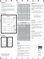
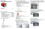
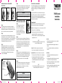
Installation Instructions for Timken THS25
Encoder Tether
Electrical Connection Information
Step 4
Using a dial indicator on the outside of the encoder body, check the
runout as you rotate the shaft by hand. If it exceeds the maximum
allowable 0.005 in. the encoder will need to be re-installed or
adjusted. The installation is complete.
CAUTION
Failure to observe the following cautions could cause property damage.
Excessive runout will cause premature bearing failure.
3 Point Flex Mount
8.5 in. C-Face Tether Arm 4.5 in. C-Face Tether Arm
Step 1
Ensure mating parts line up, bolt thread pitches and lengths are
appropriate and tools are the correct type and size. Please refer to
any additional motor manufacturer’s installation instructions, as there
may be some critical measurements or required hardware.
Step 2
Check and remove burrs on the mating shaft and measure to ensure
the shaft length is correct for the encoder. The shaft should engage
the encoder beyond the shaft clam by 1/2 in. or more. Attach the tether
to the encoder body and slide the assembly onto the mating shaft.
Do not tighten the shaft clamp on the encoder yet.
Step 3
Rotate the tether arm until it is at the correct orientation and is
aligned with the mounting feature on the shaft housing. Use the
appropriate hardware to secure the tether arm in position. Check
to ensure the tether is still in its “unstressed’ condition (move the
encoder slightly if necessary). Tighten the shaft clamp on the
encoder as shown in Fig. A.
Fig. A
Recommended
Bolt Torques
THS25 Clamp Bolt
#6-32 Socket Head
Cap Screw
10 to 15 lb-in. 7/64 in.
Installation Instructions for Timken
THS25 Encoder using Block and Pin
Step 1
Ensure mating parts line up, bolt thread
pitches and lengths are appropriate
and tools are the correct type and size.
Please refer to any additional motor
manufacturer’s installation instructions, as
there may be some critical measurements
or required hardware.
Proper wiring and grounding are essential for the longevity and proper
operation of your Timken THS25. In addition, electrical noise must be
minimized to prevent improper counts and damage to the electronic
components.
THS25 Encoder
Installation
Instructions
Because a Timken THS25 can be used with a wide variety of input
devices (PLC’s, counters, servo controllers, etc.), from many different
manufacturers, it is important to determine proper wiring and
connections before. Please review the Wiring Table included in these
instructions before installation.
Common Signals
Timken THS25 encoders have the following electrical connections:
Power, Common or Ground, and one or more Output Signals.
Power (Also called supply, power source, encoder power, +V, or +VDC)
• Always use a direct current (DC) voltage.
• Attach power to the positive (+) side of the power source.
Block and Pin
Step 2
Drill a hole in the casing to accept the tether pin. Follow the motor
manufacturer’s instructions for diameter, depth and location of the
hole. Make sure it is in the proper orientation relative to the tether
block placement so that the finished installation will be “clocked”
correctly. Insert the tether pin to the correct depth using a press fit.
The pin depth should never exceed or interfere with the motor
spinning mechanisms.
Step 3
Check and remove burrs on the mating shaft and measure to ensure
the shaft length is correct for the encoder. Firmly attach the slotted
tether to the encoder body and slide the assembly onto the mating
shaft. Rotate the encoder body engaging the pin into the tether.
Tighten the shaft clamp on the encoder as shown in Fig. A.
Step 4
Using a dial indicator on the outside of the encoder body check the
runout as you rotate the shaft by hand. If it exceeds the maximum
allowable 0.005 in. the encoder will need to be re-installed or
adjusted. The installation is complete.
• Verify the Timken THS25 is receiving the proper voltage.
Most electrical failures are caused by an improper or improperly
regulated power source.
Connections
Note
To avoid disabling or damaging the encoder, the use of surge
protection is highly recommended.
Common (Also called Com, supply common, and ground)
• Verify and match up pin numbers, wire colors, or terminal
blocks with the input device.
• Be aware, identification terminology may not always be
identical.
• Attach common to the negative (-) side of the power source.
• Once proper wiring is determined, document it for future reference.
Output Signals (Always at least one, but may be as many as six)
Cable Routing
• The common are A, B, and Z. with open collector configuration
• Cable length should be minimized by using the shortest
route possible.
• Encoders with a Line Driver output have the complement
(A and A’, B and B’, etc.) as separate outputs. These are used
to provide differential signals for reduced noise and greater
drive capability.
Note
To avoid disabling or damaging the encoder, never connect
the output signals together, or to the power source.
• All cabling should be installed in dedicated metal conduits, or located at least 12 in. away from other wiring.
• Route cables away from high current conductors to minimize pulses caused by electrical transients.
• Signal wire continuity should be maintained from the encoder
to the controller/counter. Avoid junctions and splices,
if possible.
CAUTION
Clamp bolt
Failure to observe the following cautions could cause property damage.
Excessive runout will cause premature bearing failure.
661_Encoder Instruct Sht.indd 1
7/14/09 3:21:02 PM
Radiated Electrical Noise
Wiring Table
• Ensure all equipment is properly grounded. (Motors, drives, shafts, etc.)
• Connect encoder cable shield to ground at controller/counter end, leaving the end near the
encoder unconnected.Connecting the shield at both ends can cause ground loops, and
improper operation.
• If possible, use differential line driver outputs with high quality shielded, twisted pair cable. (Complementary signals greatly reduce common mode noise levels, as well as signal distortion resulting from long cable lengths.)
Typical Electrical Hook-Ups
Erratic Output/Missing or Extra Counts
Function
Gland
Cable Wire
Color
5-pin
M12
8-pin
M12
Com
Black
3
7
F
+VDC
White
1
2
A
Brown
4
A’
Yellow
B
7-pin MS
OC
6-pin MS
10-pin
Bayonet
F
F
A,F
F
D
D
D
B
D
1
A
A
A
D
A
• Mechanical: Check for improper alignment or loose coupling. Counts indicate
wrong direction
—
3
H
C
—
—
H
• Check for reversed wiring of the quadrature signals. Reverse if needed.
Red
2
4
B
B
B
E
B
• If differential signals are being used, make sure both sides are properly wired.
B’
Green
—
5
I
E
—
—
J
Z
Orange
5
6
C
—
C
C
C
Z’
Blue
—
8
J
—
—
—
K
Case
—
—
—
G
G
G
—
G
Shield
Bare
—
—
—
—
—
—
—
10-pin MS 7-pin MS
LD
Note
If an index pulse is being used, reversing the wiring
will cause the reference alignment to change.
Counts In Only One Direction
• Make sure the counter/controller is capable of, and programmed for,
bi-directional counting.
Encoder Connector Cable Assembly Wiring
STANDARD
FUNCTION
Output Circuit Diagrams
10 PIN
MS
7 PIN MS
TWISTED PAIR
6 PIN MS
12 PIN
• Electrical: Check for loose wiring connections, ground loops, encoder outputs
incompatible with the counter/controller, a noisy power supply, electrical noise,
proper termination of shields, or a combination of these problems.
M12 CORDSET
10 PIN
MS
7 PIN
MS
6 PIN
MS
8 PIN
5 PIN
LD
OC
LD
LD
OC
LD
OC
LD
OC
LD
LD
LD
COM
Black
Black
Black
Black
Black
Black
Black
Black
Black
Black
Blue
Blue
+VDC
Red
Red
Red
Red
Red
Red
Red
Red
Red
Red
Brown
Brown
A
White
White
White
Orange
White
White
White
White
White
White
White
Black
A’
Brown
Brown
----
White
----
Brown
----
Black
Black
Black
Green
----
B
Blue
Blue
Blue
Green
Green
Blue
Blue
Blue
Blue
Blue
Yellow
White
B’
Violet
Violet
----
Blue
----
Violet
----
Black
Black
Black
Gray
----
Z
Orange
----
Orange
----
Orange
Orange
Orange
Yellow
----
----
Pink
Gray
Z’
Yellow
----
----
----
----
Yellow
----
Black
----
----
Red
----
Case
Green
Green
Green
----
----
Green
Green
Green
Green
----
Bare*
Bare*
Shield
Bare
Bare
Bare
Bare
Bare
Bare
Bare
Bare
Bare
Bare
Bare
Bare
Com Sense
----
----
----
----
----
Gray
Gray
----
----
----
----
----
+VDC
Sense
----
----
----
----
----
Pink
Pink
----
----
----
----
----
• On quadrature units, both channels (A and B) must be present and operational.
Check by using a dual channel oscilloscope.
• Make sure the input selection type programmed into the counter/controller,
matches the Timken THS25. If there is a mis-match, the system may not
work properly.
Index Pulse Not Working
• The index pulse occurs only once per revolution, and can be difficult to check
with a volt meter. Check index pulses with an oscilloscope.
• The counter/controller may not be capable of detecting the index pulse at
higher RPM’s. Slowing down the rotation may allow for detection of the
index pulse.
• Verify wiring.
*Only on specified cordsets
Troubleshooting
No Output/No Counts
Open Collector
Line Driver
Every reasonable effort has been made to ensure the accuracy
of the information contained in this writing, but no liability is
accepted for errors, omissions or for any other reason.
661_Encoder Instruct Sht.indd 2
• If there is no mechanical movement, there will be no output. Therefore, verify that the
Timken THS25 is rotating.
• Check to make sure the proper supply voltage is present. It is best to do this at the Timken THS25 end, if possible.
• Verify all wiring between the Timken THS25, the counter/controller, and the power supply.
www.timken.com
• Make sure the proper signal type (OC, LD) is being used for the application.
Timken® is a registered trademark of
The Timken Company
• Verify the counter/controller is properly installed and operational. Consult the appropriate
counter/controller User’s Manual if necessary.
• If another Timken THS25 is available, try it to determine if the encoder is the problem.
© 2009 The Timken Company
Printed in U.S.A.
5M 07-09-29 Project No. 0661
7/14/09 3:21:02 PM