1
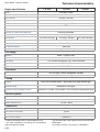
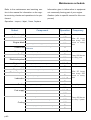
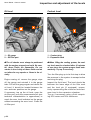
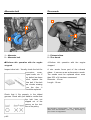
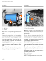
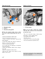
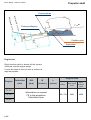
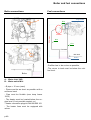
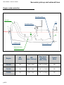
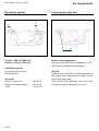
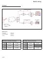
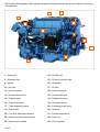
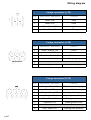
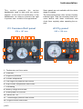
Reference : 970 313 790
Date : 06/2007
Indice : A
Common Rail
English
This photograph does not
necessarily represent the
engine
Technical characteristics
Nanni Diesel - Owner’s manual
Engine specifications
T4.165
T4.180
4 strokes, Diesel
Cycle
4 in line
Number of cylinders / Arrangement
Bore / Stroke
96 mm x 103 mm
Displacement
2,982 litres
16 valves, gears & belt
Distribution
17,9/1
Compression rate
Turbo Intercooler
Aspiration
Direction of rotation (from flywheel)
Counter clockwise
Weight dry with gearbox (TTM40A)
362 kg
Max. power*
T4.200
121,5 kW (165 hp)
132,5 kW (180 hp)
147,2 kW (200 hp)
3400 rpm
Max rated rpm speed*
700 to 750 rpm
Idle rpm speed
4000 rpm
No load rpm speed
236 g/kW/h at 3400 rpm
Specific fuel consumption
Fuel supply
Direct - Common Rail
Injection
1-3-4-2
Injection order
11,8° at 3400 rpm before TDC, ECM controlled
Fuel timing
DENSO HP3
Injection pump
Up to 180 MPa, ECM controlled
Injection pressure
Lubrication
API CD-SAE 15W40 (temperate climate)
Engine oil
6,4 to 7,7 litres depending inclination
Engine oil capacity
Cooling
Cooling
Dual circuit sweet water / sea water with heat exchanger
Neoprene rotor type
Seawater pump
Coolant for heat exchanger version
Around 15,5 litres, 50% water + 50% mixture of antifreeze and
Electrical system
Alternator
12 V / 100 A
Alternator belt tension
Auto-tensioner
Battery capacity (min.)
110 A/h - 400A
Connections
Exhaust
90 mm
Fuel (suction and return)
10 mm
Seawater
38 mm
Max. mounting angle
I These specifications are for marine pleasure only.
* For more information concerning your transmission,
refer to its specific manual.
p.A2
7° (dynamic)
The recommended cruise speed is 200 rpm below rated
RPM speed.
*At engine flywheel, according to ISO 8665-1.
Maintenance schedule
Refer to the maintenance and servicing sec-
Information given in italics refers to equipment
tion in the manual for information on the regu-
not necessarily forming part of your engine.
lar servicing checks and operations to be per-
Gearbox (refer to specific manual for this com-
formed.
ponent)
Operation : Inspect , Adjust, Clean, Replace
Subset
Fuel supply
Exhaust elbow
Component
Fuel filter
Zinc anode
Tension of belts
Engine block
Tightening of attaching parts and clamps
I/R
R
I/A
Cables accelerator / reverse, Trolling, General
lubrication
Fuel supply
Air filter (cleaning kit)
I/C/R
Cooling
Seawater pump rotor
R
Starter (attachment)
I/A
Alternator (attachment)
I/A
Engine block
Fuel supply
Engine block
Electrical system
Lubrication
Cooling
Cleaning and protection of engine
Fuel pre-filter (cartridge)
Attachment of engine suspensions / alignment
Fuel supply
I/A
R
I/A/R
Gearbox oil filter
R
Cooling circuit (rinsing)
C
Calibration of injectors
Coolant change
Every 200 hours
or every year
Every year
R
Engine oil (change)
Turbo
Cooling
I/A/C
I
Adjustment of valve clearance
After 20 hours
then every 100
hours or every
year
I
Battery
Engine oil filter
Frequency
R
Control unit
Electrical system
p.A3
Operation
After 20 hours
then every 200
hours or every
year
Every 2 years
I/A
I/A/R
I/C
R
Exchanger manifold or keel cooling
I/C
Gearbox oil cooler manifold
I/C
Calibrated plug of temperature exchanger
R
Thermostat
R
Every 400 hours
or every 2 years
Inspection and adjustment of the levels
Nanni Diesel - Owner’s manual
Oil level
Coolant level
1
2
1
1 - Oil gauge
2 - Oil filler port
1 - Coolant plug
2 - Expansion tank
I The oil checks must always be performed
with the engine stopped and cold. Be careful, these fluids are flammable. Do not
smoke in the vicinity of these fluids and do
not allow for any sparks or flame in the vicinity.
I When filling the cooling system, the coolant level must be checked after 10 minutes
of use since the system purges itself automatically. Top up if necessary.
Engine casing oil: remove the gauge, wipe
off the gauge and reinstall it in the gauge
tube. Pull out the gauge again and check the
oil level. It should be located between the
min. and max. positions on the gauge.
If necessary, top up the oil level: open the
air filler port, pour the recommended oil (see
technical characteristics in appendices) to
reach the max. level indicated on the gauge
without exceeding the max. level. Close the
oil filler port.
p.A4
Turn the filler plug up to its first stop to allow
the pressure in the system to escape before
removing the plug.
Inspect the fluid level. The level should be
between the lower edge of the filler neck
and the level pin (if equipped), respectively representing the minimum and maximum level in the expansion chamber.
Top up if necessary using a fluid comprising 50% water and 50% antifreeze.
Alternator belt
Zinc anode
1
2
2
1
1 - Alternator
2 - Alternator belt
1 - Exhaust elbow
2 - Zinc Anode
I Perform this operation with the engine
stopped.
I Perform this operation with the engine
stopped.
Inspect drive belt : Visually check the belt for
exc ess ive
w ear,
frayed cords, etc. If
any defect has been
found, replace the
drive belt. If the belt
has chunks missing
from the ribs, it
should be replaced.
A zinc anode forms part of the exhaust
elbow . It serves as an anticorrosion anode.
The anode must be replaced when more
than 50% of it has been consumed.
Diameter : 10 mm
Length : 16 mm
Check that it fits properly in the ribbed
grooves. Check with your hand to confirm that
the belt has not
slipped out of the
groove on the bottom of the pulley.
p.A5
Non-bin ding pho tographs . The coupl ed equip men t and accessories can vary accordi ng to
your level of equ ip men t.
Nanni Diesel - Owner’s manual
Air filter
Fuel filter
2
1
1
1 - Air filter
2 - Clamp
I Be sure no impurities get into the engine.
Remove the clamp from the hose and remove the filter. Remove the spring inside the
filter. If necessary, clean the filter by washing it with soapy water. Then, rinse the filter
with clear water. Press the filter to remove
any water and to dry it.
NANNI DIESEL has designed a cleaning kit
which is suited to certain models of the air
filter.
Use of this kit is recommended on our engines to perform effective cleaning and ensure good engine « breathing ».
p.A6
1 - Fuel filter cartridge
I Always sponge up any fuel which may
have spilled Observe the environment protection rules.
The fuel filter is a throw-away type filter. The
fireguard envelope and the water probe must
be preserved and reinstalled correctly (if
equipped). The fire guard must not come into
contact with the plastic purge screw.
-Close the fuel valve
-Unscrew the cartridge from the filter head
-Coat the seal of the new cartridge with clean
oil
-Screw the new cartridge on the filter head,
then tighten by hand by ¾ turn (do not use a
tool).
-Reinstall the probe and the purge screw (if
equipped). Check the seal
-Open the fuel valve
-Purge the circuit
-Start up the engine and check for any leaks
Sea-water pump
Engine oil drain
1
2
1
3
1 - Sea-water pump
2 - Impeller
3 - Sea-water pump gasket
I Close the seawater intake valve as there
is a risk of water penetrating into the engine.
-Close the seawater intake valve
-Close the seawater pump cover
-Using a channel lock pliers, remove the
worn Impeller
-If the rotor shows any signs of cracks or
defects, it should be replaced
-Clean the parts preserved
-Fit a new rotor by applying a clockwise
rotary movement
-Install the seawater pump cover using a
new seal
-Open the seawater intake valve
-Start-up the engine and check for any
leaks in the circuit
p.A7
1 - Oil drain pump
I Hot oil can burn. Avoid any contact
with the skin. Observe the environment
protection rules.
-The oil is removed using a drain pump,
preferably: engine slightly warm,
-Fully pump out all the oil,
-Fill with new oil,
-Check the oil level using the gauge,
-Do not exceed the maximum level.
Non-bin ding pho tographs . The coupl ed equip men t and accessories can vary accordi ng to
your level of equ ip men t.
Propeller shaft
Nanni Diesel - Owner’s manual
Coupling flange
r bo
Moto
x 0.1
i
5 min
x 0.1
ats Ø
Ø
oats
Sail b
7° m ax
Floating stuffing box
mini
Flexible mount
Engine bed
Engine bed
Rigid structure able to absorb all the dynamical stress, and the engine weight.
It must be linked to the hull with a surface as
large as possible.
Engine RPM
Engine
Reduction
ratio
ØA
(mm)
Ø
(inches)
L
(meter)
Idling
Maxi rated
load
Maxi
without
load
700 / 750
3400
4000
T4.165
T4.180
T4.200
p.A8
Information on request
Fill in the propulsion
Calculation form
Boiler and fuel connections
Boiler connections
Fuel connections
Engine filter
A
Ø10
0.5 m max
Prefilter
B
Ø10
Ø10
Fuel tank
Mini level
Return
-Prefilter has to be as low as possible,
-The return to tank must be below the mini
fuel level.
Boiler
A - Water inlet 3/8G
B - Water outlet M14
- Ø pipe = 15 mm (maxi)
- Pipes must be as short as possible with a
minimum bend
- Pipe must be flexible (max temp hoses
100°c)
- The heater must be located below the engine level (if not possible contact us.)
- Heater connection plugs kit Ref 899 000 163
- The heater lines must be equipped with
valves
p.A9
Sea water pick-up and exhaust lines
Nanni Diesel - Owner’s manual
Engine under waterline
Hose ØE
Filter
i
ma x
0.15m
3m
0.15m
Anti-siphon Ø38
2 m maxi
0.5 m mini
Sea-water pump
Waterline
ØE
ØD
Exhaust outlet
Sea cock valve
Water lock useful
volume V
Engine
ØD
(mm)
ØE
(mm / inches)
Max backpressure
(kPa / PSI)
V mini
(litre)
T4.165
38
90 / 3.54’’
28.7 / 4.162
20
T4.180
38
90 / 3.54’’
28.7 / 4.162
20
T4.200
38
90 / 3.54’’
28.7 / 4.162
20
p.A10
Engine under waterline
Sea-water pump
Hose ØE
Waterline
0.3 m mini
ØE
0.15m
Filter
ØD
Water lock useful
volume V
Sea cock valve
Exhaust outlet
All sail boat
Anti syphon valve
Must be at the end of raw water piping
before exhaust elbow inlet
Water lock
Must be always lower and near the engine
p.A11
Motor boats
Air requirement
Nanni Diesel - Owner’s manual
Dynamical system
S2
Forced system (by fan)
S1
fan
S1 mini = 580 cm2 (680 cm2 )
S2 mini = 310 cm2 (360 cm2)
Engine room temperature
Nor more than 50°C with a difference of 15°C
(20°C maxi) with ambient temperature.
Ventilation system
Dynamical (for fast boat)
Forced (by fan)
Air needs
Outlet of warm air :
Engine air consumption :
Total :
p.A12
900 m 3/h
620 m 3/h
1520 m 3/h
Air flow
Fresh air inlet, on the front in the lower part of
the engine room and warm air outlet on the
back in the upper part.
Avoid short-circuit between inlet and outlet
in order to have a maximum air move.
Electric wiring
C3 Panel
Y Fly
Wheelhouse extension
L1
C3 Panel
Red 2mm2
Fly Bridge extension
L2
A3 Fly Bridge
panel
Battery
References:
C3 panel :
A3 Fly Bridge :
Y Fly :
674 455
674 470
674 484
Wheelhouse extension references
Fly bridge extension references
L1 =
4 meters
674 456
L2 =
4 meters
L1 =
6 meters
674 457
L2 =
6 meters
L1 =
8 meters
674 458
L2 =
8 meters
p.A13
674 427
674 443
Main parts of the engine
Nanni Diesel - Owner’s manual
26
24
27
20
11
34
4
19
41
22
10
15
25
17
16
p.A14
Non-binding photographs. The coupled equipment and accessories can vary according to your level
of equipment.
29
30
22
42
23
43
2
33
34
1
41
1 - Alternator
24 - Oil filler port
2 - Alternator belt
25 - Oil drain (suction tube
4 - Starter
26 - Oil gauge
10 - Air filter
27 - Oil filter
11 - Injection pump
29 - Heat exchanger
14 - Acceleration control
30 - Coolant filler port
15 - Turbocharger
33 - Freshwater pump
16 - Turbo drain valve
34 - Sea-water pump
17 - Turbo degassing valve
36 - Exchanger drain plug
19 - Fuel cooler
40 - Gearbox
20 - Fuel filter and water detector
41 - Flexible suspension
22 - Water injection exhaust elbow
42 - Fuse box
23 - Anticorrosion anode
43 - Circuit breaker
p.A15
p.A16
33
34
BATTERY
MAIN SWITCH
WATER TEMP. SENDER
OIL PRESSURE SENDER SWITCH
BREAKER 80A
BREAKER 120A
BREAKER 25A
FUEL FILTER
FUSE BOX
EDU RELAY
GLOW PLUGS
STARTER
STARTER RELAY
MAIN RELAY
NEUTRAL SWITCH
ALTERNATOR
35
THROTTLE SENSOR
CALCULATOR
ECM
CAMSHAFT POSITION SENSOR
CRANCKSHAFT POSITION SENSOR
SUCTION FUEL CONTROL VALVE
FUEL RAIL PRESURE SENSOR
WATER TEMP. SENSOR
FUEL TEMP. SENSOR
AIR TEMP. SENSOR
AIR PRESSURE SENSOR
RAIL FUEL PRESSURE
CONTROL VALVE
INJECTORS
GLOW PLUG PILOT
+ PILOT
+ BATTERY
CRANCKING
+ IGNITION
Nanni Diesel - Owner’s manual
Wiring diagram
4 ways connector (n° 33)
Pos.
Wire colour / size (mm2)
Function
1
Black 3.00
Earth
2
Brown 3.00
Crank
3
Red - Yellow 3.00
+ Ignition
4
Red - Blue 3.00
+ Battery
6 ways connector (n° 34)
Pos.
Wire colour / size (mm2)
Function
1
White - Orange 1.00
Check
2
Dark blue 1.00
+ Tachometer
3
Dark blue - Black 1.00
- Tachometer
4
Yellow - Black 1.00
Glow plug lamp
Grey 1.00
Oil pressure gauge
5
6
8 ways connector (N° 35)
Pos.
Wire colour / size (mm2)
Function
1
Orange - Blue 1.00
Water temperature gauge
2
Black 1.00
Earth
3
Yellow - Green 1.00
Warning water temperature
4
Purple 1.00
Warning battery charge
5
Pink - Black 1.00
Warning oil pressure
6
Light blue 1.00
Warning water in fuel
Grey - Black 1.00
Warning turbo pressure
7
8
p.A17
Nanni Diesel - Owner’s manual
Recommended on-board kit
Concerning the checks to be performed on installation (see chapter 4 on installation), you can
order the installation documentation from NANNI INDUSTRIES.
Part name
Alternator belt
Reference
970 313 801
Part name
Porte injecteur
Reference
970 314 055
Part name
Engine oil filter
Reference
970 313 306
Part name
Thermostat
Reference
370 314 033
Part name
Fuel filter
Reference
970 313 374
Part name
Air filter
Reference
970 301 330
Part name
Sea-water pump kit
Reference
970 312 432
Part name
Ano de
Reference
970 494 635
p.A18
Instrumentation
This sec tion pres ents
the various
dashboards used to date with our marine
engines. In the event of modification of the
dashboards, we reserve ourselves the right
to present new models in the appendices.
Some panels are not available with the whole
range of engines.
The instruments shown often consist of safety
indicator lights. Take the necessary time to become familiar with these instruments and
check them regularly when operating the engine.
C3 Common Rail panel
A3 Fly panel
270 x 187 mm
205 x 120 mm
9
6
5
8
7
11 12
9
6
5
4
3
12
11
1
2
10
1
1 - Tachometer and hour meter
2 - Voltmeter
3 - Engine oil pressure
4 - Coolant temperature
5 - Low engine oil pressure with buzzer
6 - High coolant temperature with buzzer
7 - Preheating
8 - Battery charge with buzzer
9 - Water present in fuel filter
10 - Switch on / off
11 - Turbocharger pressure with buzzer
12 - Engine control with buzzer
p.A19
8
10
ERROR: syntaxerror
OFFENDING COMMAND: --nostringval-STACK:
/Title
()
/Subject
(D:20080919090415+02’00’)
/ModDate
()
/Keywords
(PDFCreator Version 0.9.5)
/Creator
(D:20080919090415+02’00’)
/CreationDate
(HUVETEAU)
/Author
-mark-