1
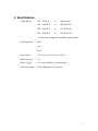
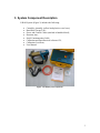
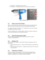
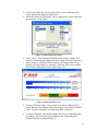
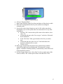
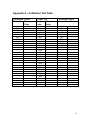
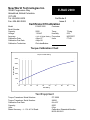
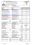
Table Of Contents 1. 2. 3. 3.1. 3.2. 3.3. 3.4. 3.5. 3.6. 4. 5. 6. Introduction................................................................. 1 Specifications.............................................................. 2 System Component Description ................................. 3 Controller Assembly ........................................................................................... 4 Hand Held Tool................................................................................................... 4 Power and Control Cables .................................................................................. 5 Serial Communication Cable .............................................................................. 5 Software CD........................................................................................................ 5 Calibration Certificate......................................................................................... 5 System Setup............................................................... 6 Operation Instructions................................................. 7 Calibration Procedure ................................................. 9 6.1. Calibration Equipment ........................................................................................ 9 6.2. Calibration Period ............................................................................................... 9 6.3. Calibration overview........................................................................................... 9 6.4. Calibration Software ......................................................................................... 10 6.4.1. Installation................................................................................................. 10 6.4.2. Uninstalling E-RADCal program ............................................................. 10 6.5. Calibration Software Operation ........................................................................ 10 6.6. Calibration Testing............................................................................................ 13 6.7. Calibration Adjustment Example...................................................................... 14 7. 7.1. Data Retrieval ........................................................... 15 Data Retrieval Operation .................................................................................. 15 Appendix A – Calibration Test Table............................... 18 Appendix B – Sample Calibration Certificate .................. 19 Appendix C – Selector Switch Option.............................. 20 Appendix D – Torque Angle Option ................................ 21 Appendix E – Contact Information................................... 23 IMPORTANT: DO NOT OPERATE THE TOOL BEFORE READING THIS USER MANUAL. IF BREAKDOWN, MALFUNCTION OR DAMAGE OCCURS, DO NOT ATTEMPT TO REPAIR. CONTACT NEW WORLD TECHNOLOGIES INC. OR YOUR LOCAL DISTRIBUTOR IMMEDIATELY. IMPORTANT: WHEN USING A POWER PLUG ADAPTER, MAKE SURE THE EARTH GROUND PIN IS PRESENT AND CONNECTED IN THE ADAPTER. NEW WORLD TECHNOLOGIES INC. DOES NOT RECOMMEND REAPLCING THE SUPPLIED POWER CORD. IN THE EVENT THE POWER CORD IS REPLACED MAKE SURE THE NEW POWER CORD HAS AN EARTH GROUND PIN. 1. Introduction The E-RAD electric torque wrench tool is a highly accurate and repeatable bolt torque system. The E-RAD is self-contained, portable, and operates with the use of a standard 115V or 220V AC power source. Its rugged, splash-proof design makes it fully capable of operating in harsh industrial environments. E-RAD is also offered in an upright heavy duty steel case. Torque value is set via two buttons on the touch pad mounted on the main unit. Torque is applied when the trigger on the hand tool is pressed. Both torque set and achieved torque are displayed on the LCD display, in a variety of user-selectable units. The E-RAD Torque Wrench is available in several torque ranges, from 700 (950) lb-ft (Nm) to 3000 (4050) lb-ft (Nm). Custom torque ranges are available upon request. Figure 1: E-RAD System 1 2. Specifications Torque Range: 300 – 700 lb-ft or 400-950 Nm 300 – 1200 lb-ft or 400-1600 Nm 500 – 2000 lb-ft or 675-2700 Nm 500 – 3000 lb-ft or 675-4050 Nm *Custom torque ranges are available up upon request Units Supported: Lb-Ft Nm Kg.F Power Source: 115V AC @ 10A or 220V AC @ 5A Stated Accuracy: 3% Cables Length: 15 ft / 4m, 18 ft/6m, or custom length Control Assembly: Yellow hard plastic or steel case 2 3. System Component Description E-RAD System (Figure 2) includes the following: • • • • • • • • Controller Assembly (yellow hard plastic or steel case); Hand Held Torque Tool ; Power and Control Cables (attached to hand held tool); Reaction Arm; Serial Communication Cable; Calibration and Data Retrieval software CD; Calibration Certificate; User Manual. Figure 2: E-RAD System components 3 3.1. Controller Assembly The Controller Assembly contains a motor power source and motor drive controller for the hand held tool. Four connectors on the side of the unit (Figure 3) provide interface to the Controller Assembly: • Main Power Connector (1) - 115V AC (or 220V AC, depending on the unit) main power input; • Serial Communication Connector (2) – standard PC serial communication interface. • Hand Held Tool Power and Control Connectors (3) – military style connector provide interface between the Controller Assembly and the Hand Held Tool. 2 3 1 Figure 3: Controller Assembly Connections User Interface (Figure 4) is provided by: • 3 Button Touch Pad Overlay (1)– provides the user the ability to increase/decrease and change the units of measurement of the torque setting; • LCD Display (2) – visual feedback of the torque setting, torque achieved and direction of rotation. • On/Off main power switch (3) – connects/disconnects main power 115V AC (or 220V AC, depending on the unit). • Green Light Lens (4) – lights on when power is connected and turned on. 3 4 2 1 Figure 4: User Interface 3.2. Hand Held Tool The tool provides 2 user control switches and 3 visual status feedback (Figure 5): • On/Off Trigger switch (1) – hand tool activation; • Forward/Reverse switch (2) – controls direction of rotation FORWARD/REVERSE (CW/CCW); • System Ready light (3) – Green light when the tool is ready for use; 4 • • Fail light (4) – Red light when the tool fails; Pass light (5) – Green light when the tool completes torque operation. 3 2 4 1 5 Figure 5: Hand Held Tool 3.3. Power and Control Cables Both power and control cables are hard wired in the factory to the hand tool. Each cable is secured with a spring strain relief to provide durability and flexibility. The length of the cables is normally 15’/18’ in length, but can be custom ordered to any length specified by the customer. Cables are terminated with ¼ turn lock military style metal connectors and provide secure and solid connection to the Controller Assembly. 3.4. Serial Communication Cable This cable enables serial communication interface between the Controller Assembly via standard RS232. 3.5. Software CD E-RAD software CD contains 2 custom made windows based programs for the ERAD system: • E-RAD Calibration software – enables Lab/Field calibration of the hand held tool; • E-RAD Data Retrieval Software – enables the retrieval of up to 750 successful torque operations. 3.6. Calibration Certificate Each unit is calibrated with compliance to ISO 10012 using equipment that is calibrated according to known industry accepted standards traceable via NIST standards. See appendix A for a Calibration Certificate Sample. 5 4. System Setup Caution Before plugging in main power cord or Hand Held Tool cables; make sure main power switch is in the OFF position. Failure to comply may result in equipment failure or equipment damage Before powering up the unit, perform the following steps: Caution Do not force the connectors onto the Controller Assembly. Failure to comply may result in damage to the connectors. Caution Never lift the tool by the cables. Do not pull excessively on the cables or drag the Controller Assembly by pulling on the cables. Failure to comply may result in damage to equipment. • • • • Align control cable notch to the notch in the controller Assembly. Push the connector in forward and turn clock wise at least ¼ turn until the plug locks into the connector on the case; Align power cable notch to the notch in the controller Assembly. Push the connector in forward and turn clock wise at least ¼ turn until the plug locks into the connector on the case; Connect main AC power plug to an appropriate AC power source (115V AC or 220V AC according to the model); Make sure serial communication cable is disconnected. 6 5. Operation Instructions This section details the operation of the E-RAD system. Caution Make sure that all connectors are secured prior to turning the power switch ON. Failure to comply may result in equipment failure and/or equipment damage. When the tool is in operation, the Reaction Arm rotates in the opposite direction to the Output Square Drive and must be allowed to rest securely against a solid object or surface adjacent to the bolt to be tightened (Figure 6). Warning Keep hands clear of the reaction arm when the tool is in use. Failure to comply may result in serious injury. Figure 6: Reaction Arm • • • • Turn main power switch to ON position. Green ON light on the controller Assembly is illuminated. Once internal self test is completed and passed, the System Ready light on the hand held tool is illuminated. The display will flash model and firmware revision for 2 seconds, then displays on the top row, last used torque setting and on the bottom row, the actual torque reading. Readings are in the recently used units of measurement. To increase torque setting, press on the INCREASE arrow. If maximum value of torque setting is reached, the displayed value does not change. If the buttons are pressed briefly, the torque changes by a single count. If the buttons are held down for 3 seconds, the torque will start to change in single counts, then in increments of 10 counts, and finally in increments 100 counts. To decrease torque setting, press on the DECREASE arrow. If minimum value of torque setting is reached, the displayed value does not change. If the buttons are pressed briefly, the torque changes by a single count. If the buttons 7 • • • are held down for 3 seconds, the torque will start to change in single counts, then in increments of 10 counts, and finally in increments 100 counts. To change units of measurements press on UNITS. The units will cycle between Ft.Lb, Nm and Kg.F. Set the torque to the setting required for your application. To perform a torque operation: o Make sure the torque setting is correct; o Couple the hand held tool to the bolt; o Make sure the direction switch is set to forward (verify display does not show REVERSE on the bottom row); o Make sure reaction arm has a proper and safe point of reaction; o Depress the ON/OFF trigger and keep it pressed until the hand held tool stop rotating and the Pass light illuminates. The hand held tool operates until the torque reaches the preset value (Pass indicator Illuminated), and then stops automatically. If the Trigger is released before the set torque is reached, or the tool fails to reach the required torque, the Failed indicator light is illuminated. o To clear an error or a failed indicator illumination set the direction switch to REVERSE (bottom line of LCD displays “REVERSE”) Any error or failed indicator illumination is cleared; Holding the Trigger depressed causes the tool to operate in the reverse direction as long as the Trigger is depressed. o If the tool is unable to reach the correct torque, switch the Direction switch to reverse, and back the bolt off for a couple of seconds, then repeat the torque operation. IMPORTANT NOTE: If the tool is running for more than 20 seconds and the correct torque is not reached, the tool stops, and the Red Failed indicator illuminates on the handgrip. o Once the set torque is reached and the green Pass light is illuminated, the tool reverses direction for a short pulse motion to release the chuck from the bolt. • • Upon completion of the bolting job or at the end of the day, power down the controller assembly by turning the ON/OFF switch to OFF. It is not necessary to disconnect the cables from the controller assembly. Download the torque records to a Personal Computer (windows based) if desired (recommended at the end of a job). See section 8. 8 6. Calibration Procedure All E-RAD systems leaving New World Technologies Inc are calibrated in the Lab prior to shipping. A Calibration Certificate (see appendix B) is issued for each tool and shipped with each tool. 6.1. Calibration Equipment Basic requirements: • Personal Computer with CD-ROM and a serial port or a USB port with a USB-SERIAL adapter; • Windows NT, Windows 2000 or Windows XP; • Torque measuring equipment (display, transducer, ETC.) 6.2. Calibration Period New World Technologies Inc recommends that the system be calibrated once a year according to the date specified on the Calibration Certificate. The calibration period complies with industry standards for precision measuring devices. Customers may wish to perform calibration in their facility at different intervals within the period listed above for various reasons: • Tool was exposed to extreme temperatures • Rough handling or significant shock to the system • Tool seems to be exceeding the accepted torque error or tolerance margin. 6.3. Calibration overview To perform E-RAD calibration, the controller assembly must be connected to a PC via a serial cable. The PC must have the E-RADCal calibration software installed prior to calibration.The hand held tool must be coupled to a suitable test jig fitted with a torque sensor. Using the calibration software, ten calibration output settings are selected on the tool. Torque is applied to the calibration jig using these settings, and the resulting torque values as measured by the torque sensor are recorded. The ten torque readings are then entered into the calibration software, and the calibration data is downloaded to the tool. 9 6.4. Calibration Software This is standard windows based software and is included with every shipped tool. 6.4.1. Installation To install E-RADCal software: • Place the E-RADCal software CD in the CD-Rom drive; • If installation does not start automatically, select my computer and double click (open) on the CD-ROM drive. Select and double click the “setup” file; this will launch the installation program. • Software is installed in the default folder used by the installation program; • If prompt to select the users allowed to use this software, you may want to use “everyone” so all users have access to the calibration software; • Select “Next”; • Select “Install” • Select “Finish” • Installation is completed with a placement of a short cut in the Start Menu. 6.4.2. Uninstalling E-RADCal program If for any reason you desire to remove the calibration software, follow these steps: • Click on Start Menu; • Select Control Panel; • Select Add/Remove Programs; • Find and select E-RADCal in the program list and click on the Remove Button to remove the software from your computer. 6.5. Calibration Software Operation Before launching the calibration software, make sure the calibration system is set up as follows: • Serial Cable is connected between the computer and the controller assembly. Use the supplied USB to Serial adapter provided with the tool if you are using a computer that has only USB ports and no Serial port; • Control assembly in connected to main power source; • Hand held tool is coupled to the calibration fixture with a transducer in place; • Turn ON/OFF switch on the controller assembly to ON position; • Wait until the System ready green light is illuminated on the tool. On the Computer: 1. Click on Start Menu 2. Select “all programs” 3. Find and select “E RAD” then select “Rad Calibration” 10 4. Click on the PORT tab, top left corner of the screen. Communication screen appears and display available ports. 5. Select the serial port (COM port) you are connected to, chose 9600 baud rate and node 2 as in figure 7. Figure 7: Communication Port Setup 6. Select “Okay”. Screen displays that Mint found at these settings. If no mint drive found message appears then the settings selected are incorrect. 7. Once connected, calibration values under the percentage intervals are displayed. Screen displays “Connected” at the top of the screen and the New World Technologies Globe rotates (Figure 8); Figure 8: Main Calibration Screen 8. To enter calibration mode, click on the Green “Enter Calibrate Mode” button. Button color changes to Red and displays “exit calibration mode”. Center Top screen displays “In Calibration Mode” (Figure 9); 9. To begin calibration, click the percentage intervals in a sequential order, according to the motor power percentage desired. Tab background changes from blue to purple (Figure 9); 11 Figure 9: Start Calibration Screen Attention: Under Current Motor Load Setting, 3%, 5%, 7% are used in special applications. These values must read 0 in the calibration page and saved as 0 to the E-RAD. 10. Select 10%, motor load to limit motor power output to 10%, and so on. 11. Make sure direction switch on the tool is in Forward position (REVERSE does not appear on the controller assembly display); and depress the trigger on the tool to torque. Do not let the trigger go until the tool stops automatically. 12. If the tool is stopped and the green Pass light on the tool is not illuminated or the Fail red light is illuminated, place the direction switch in REVERSE and depress the trigger for a coupe of seconds. Repeat step 12. 13. Record the reading on the transducer’s display, take a couple more readings to make sure that the readings are in the same value range and take the average of the values. 14. In the Calibration Torque table, place the cursor in the text box to the right of the label value of 10% and type the average value calculated in the previous step. Press Enter. Attention: Enter must be pressed after every entry, otherwise the value will not be recorded. 15. Repeat steps 11 to 15 for the other settings of 20% - 100% load; 16. Click on “Save Settings”. A “busy” message appears above the buttons. This means that the controller communicated the calibration values to the computer and the values are saved. 17. Turn ON/OFF switch on the controller assembly to OFF position; 18. Disconnect Serial Cable from the controller assembly. 12 6.6. Calibration Testing After calibrating the tool it is recommended to perform a calibration test to verify the tool’s accuracy and validity of the calibration values: 1. Turn ON/OFF switch on the controller assembly to ON position; 2. Press on DECREASE button of the touchpad overlay on the controller assembly until the set torque value displayed is at the lowest setting (value stops changing); 3. Set the tool in Forward direction and depress the trigger. Let the tool stop automatically and make sure that the Pass light illuminates without the fail light. Record the value displayed on the transducer’s display. 4. Set the tool in REVERSE and depress the trigger for a few seconds. Repeat previous step. After the second reading, record the average value of the 2 readings observed on the transducer’s display; 5. Press on INCREASE button to increase the set torque value and repeat previous step for all torque settings in 100 increments until the maximum torque is reached (set torque value does not change); 6. Record the averages in a table, such as the one depicted below. A blank table can be found in Appendix A. Make copies of the sheet and use as needed. Calibration Values Motor % Torque Value 3% 0 5% 0 7% 0 10% 230 20% 490 30% 720 40% 960 50% 1210 60% 1470 70% 1720 80% 1950 90% 2150 100% 2300 Torque Test Set Transducer Value Value 0 0 0 0 0 0 300 303 400 360 500 489 600 575 700 680 800 796 900 899 1000 1010 1100 1099 1200 1211 1300 1304 1400 1396 1500 1502 1600 1594 1700 1703 1800 1812 1900 1916 2000 2005 Calibration Check Areas to Recalibrate 3% 0 5% 0 7% 0 10% Good 20% Adjust 30% Adjust 40% Good 50% Good 60% Good 70% Good 80% Good 90% Good 100% Good 13 7. Adjust values that are not in the accepted tolerance (goal is +/- 3%) as follows: IMPORTANT NOTE: If calibration values are increased, actual torque applied decreases. If calibration values are decreased, actual torque applied increases a) Adjust the calibration value closest to the actual torque value you want to change. Proceed to the next value to be changed if you require adjustment on a subsequent calibration value, even if the next value is farther than the one previously changed. b) In general, the farther away from the calibration value the change is made, the less it will affect the actual torque value being changed. c) A general rule for adjusting the calibration value is a ratio of 2:1 between calibration value and applied torque. For example, to make a change of +20 ft-lb to the actual applied torque, reduce the calibration value by 10. 6.7. Calibration Adjustment Example The table in section 6.8 shows the value of 20% motor power to be outside the accepted tolerance of 3%. Actual torque reading is 360 Ft-Lb whereas the value on the controller assembly is set to 400 Ft-Lb (error of 10%). To correct the calibration value, the following procedure is executed: • Controller assembly is turned off; • Controller assembly connected to a PC with calibration software installed and running; • “Connect” is selected and calibration software actively connected to the controller; • Calibration value adjacent to the 20% label is changed from 490 to 470 (2:1 ratio, i.e. to increase actual torque by about 40 Ft-Lb, reduce calibration value by 20); • Controller assembly disconnected from the PC and its power cycled; • Torque calibration is tested again for the values close to the changed range and adjustment is repeated if necessary. 14 7. Data Retrieval E-RAD torque system stores the record of up to 750 successful bolt torque operations. It does not store failed to reach torque since the user re-torques any failed attempts. The Software CD contains a program to retrieve the stored data. Minimum Requirements: 1. Windows based PC with Windows NT, Windows 2000 or Windows XP; 2. E-RAD Calibration software already installed on the same PC; 3. CD – ROM drive; 4. Microsoft Excel installed on the same PC. The software does not require installation but the following setup must be performed: 1. Insert E-RAD Calibration Software CD in to the CD-ROM drive; 2. Select my computer and double click (open) on the CD-ROM drive. Select “E-RAD Data Logger”. In the Edit drop menu (top left of the window opened) select “copy”. 3. Navigate to the folder you want to place the software in. choosing the same folder in which the calibration software was installed or on the Desktop is recommended. 4. Connect a Serial communication cable between the PC and the controller assembly. 7.1. Data Retrieval Operation Check to which com port you are connected on the PC and that there is no other program running that may use the serial port for communication. 1. Turn the ON/OFF switch on the controller assembly to ON position; 2. If running the program for the first time the following port setup screen may appear (Figure 10): Figure 10: Comm Port Setup 15 3. Select the Com port you are connected to and set Baud Rate to 9600 and Drive Node to Node 2 as depicted above. Click on “SAVE SETINGS”; 4. Main Screen appears (Figure 11) Figure 11: Data Retrieval Main Screen Fill in the following information: IMPORTANT NOTE: Download Date and Download Time are automatically retrieved from the computer. Make sure that the time set on your PC is correct. • • • • • Operator ID; Job Number; Job Location; Completion Date; Completion Time. 5. Click on “Setup” in the drop menu at the top of the page and select “Connect”. Red background “Disconnected” message changes to green background “Connected” message (Figure 12); 16 Figure 12: Connected Screen 6. Click on “Download Data”; 7. Data Logger Software opens Excel sheet and places all the data in a table. 8. Data may be manipulated in Excel by the customer according the customer needs. 9. Save the file in the desired location as and .xls file with a name that is meaningful to you; such as jobsite-date.xls or date-time.xls or any other combination: • From the “File” menu at the top left corner of the window, select “Save As”; • Click on the tab next to the “Save as type:” and select “Microsoft Excel Workbook”; • In the “File Name” field, type the name of the file you wish to save; • Click on the tab next to the “Save in:” label and choose the location in which the file is saved; • Click on “Save”. 10. Data Logger automatically disconnects the communication with the controller assembly and a red background “Disconnected” message appears. Controller Assembly memory is automatically cleared at the end of the download operation. 11. On Data Logger main screen, click of the X at the top right corner of the screen or choose “file” at the top left of the screen and select “Exit”. 17 Appendix A – Calibration Test Table Calibration Values Motor % Torque Value 10% 20% 30% 40% 50% 60% 70% 80% 90% 100% Torque Test Calibration Check Set Transducer Areas to Recalibrate Value Value 300 400 500 600 700 800 900 1000 1100 1200 1300 1400 1500 1600 1700 1800 1900 2000 2100 2200 2300 2400 2500 2600 2700 2800 2900 3000 10% 20% 30% 40% 50% 60% 70% 80% 90% 100% 18 New World Technologies Inc. E-RAD 2000 30580 Progressive Way Abbotsford, British Columbia. V2T 6Z2 Tel: 604-852-0405 Fax: 604-852-0269 Certificate # Issue # 1 Certificate Of Calibration Model Serial Number Capacity Voltage Accuracy Calibration Date Calibration Due Date Calibration Technician E-RAD 2000 Customer 2000 115VAC Temp Humidity +/-3% of Digital Setting Procedure 4-Apr-07 Units 4-Apr-08 Chris denBraber 72 deg. 52% NWT0007 FT.LB Torque Calibration Chart Torque Vs Dial Setting 2500 Torque (FT.LB) 2000 1500 1000 500 0 10 20 30 40 50 60 70 80 90 100 Dial Setting Test Equipment Torque Transducer Model Number: Torque Transducer Serial Number: Calibration Due Date: Capacity: Units: Stated Accuracy : +/- .5% of Full Scale ITF-5000 2858-1 8-Jul-07 5000 ft.lbs. Calibration Stanadard Number: MI-09-04-8041 Appendix C – Selector Switch Option Selector switch provides the ability to program up to 8 torque settings, 1 per switch position. These settings are usually the most common settings used and allow a fast switch between torque settings instead of dialing up/down the torque each time a different torque is required. This option includes a lockout key switch which enables/disables torque changes via the keypad and switch position programming. Programming a switch position: 1. Place the switch knob to the position to be programmed; 2. Turn the key to the right (in this position key removal in not allowed); 3. Press increase or decrease to reach the torque setting required; 4. if more position are required to be programmed, turn the switch know to the next position and repeat step 3; 5. After the last position programming turn the key left and remove the key; 6. Positions are now programmed and ready to use. Note: when the key is removed the keypad is disabled, pressing on any of the buttons will have no effect. 20 Appendix D – Torque Angle Option Basic ERAD torque angle option allows for one set of torque and angle values. The values (initial torque and estimated final torque after the completion of the angle motion) for the torque angle option must be specified by the customer when placing an order for an angle tool. Customer should include the following information as well: Bolt TPI, joint configuration and joint stiffness (if possible). . When the angle option is not activated, the tool acts as a standard ERAD as described in the above mentioned paragraphs. Torque Angle Activation: 1. Tool needs to be in standard ERAD operation mode. 2. Simultaneously press on INCREASE and DECREASE buttons on the 3 Button Touch Pad Overlay. 3. Verify on the LCD display that the torque changed to the proper pre-torque setting and “ANGLE” is displayed with the proper desired angle setting. Operation: Pressing on the On/Off trigger on the tool will start to torque the bolt. Releasing the trigger any time prior to reaching the set pre-torque will illuminate the fail light. Once pre-torque is reached the fail light and pass light illuminate on the tool. Pass light to indicate pre-torque is reached and fail to indicate cycle in incomplete – angle not reached. Once pre-torque setting is reached, the tool pauses for a brief moment before continuing to the angle cycle. IMPORTANT NOTE: The tool cannot be stopped once it enters the angle cycle. Tool will complete the full angle setting before stopping to achieve the best accurate result in reaching the angle. Torque Angle Deactivation: 4. Tool needs to be in Torque Angle operation mode. 5. Simultaneously press on INCREASE and DECREASE buttons on the 3 Button Touch Pad Overlay. 6. Verify on the LCD display that the torque changed to the proper torque setting and “ANGLE” is not displayed. Additional Options: Addition of a selector switch in a torque/angle tool only, allows the programming of multiple sets (up to 8) of torque with angle setting. These settings need to be specified by the customer when ordering a tool. A second option allows the programming of multiple sets (up to 7) of torque with angle setting. The 8th available setting is preprogrammed in the factory to angle 0, 21 allowing the tool to operate as a standard ERAD tool with no angle. This is not a standard option and requires the customer to place a request for upgrading to this option when ordering. 22 Appendix E – Contact Information New World Technologies Inc. 30580 Progressive Way Abbotsford B.C. Canada V2T 6Z2 Tel: (604) – 852 – 0405 Toll Free: 1-800-983-0044 Fax: (604) – 852 – 0269 Email: [email protected] www.radtorque.com 23