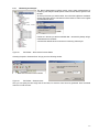
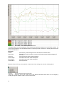
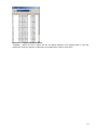
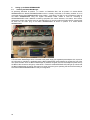
1
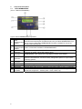
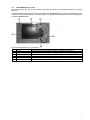
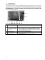
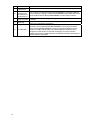
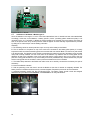
BACS WEBMANAGER
Ethernet Microcomputer for
BACS - Battery Analysis & Care System
User Manual – English
Rel.2
Limited Warranty:
This software and the enclosed materials are provided without warranty of any kind. The entire risk as to software
quality, performance of the program, media free of defects, faulty workmanship, incorrect use of the software or
UPS, error free documentation and enclosed material is assumed by the user. We do not take any warranty to the
correct functions of the software and the security of your system nor files, that might be damaged to due to possibly
not correct function of our software. No warranty to correct functions of the software with the operating systems,
loss of data or interruption of work processes, other UPS problems or to other errors that may occur out of this
combination.
Copyright:
The information contained in this manual is non-conditional and may be changed without due notice. The software
manufacturer undertakes no obligations with this information. The software described in this brochure is given on
the basis of a license contract and an obligation to secrecy (i.e. an obligation not to further publicize the software
material). The purchaser may make a single copy of the software material for backup purposes. No parts of this
manual may be transferred to third persons, either electronically or mechanically, or by photocopies or similar
means, without the express written permission of the software manufacturer.
The UPS-Management software includes a license key for each license. This license is valid for using the UPS
service on one server with one UPS and an unlimited number of connected UPSMON-WINDOWS workstations.
For operation on several servers a license for every new server is required, disregarding the fact if UPS service
runs at that location or if the server is halted by an UPS service via remote command RCCMD. The same
regulations are applicable to the use of remote send/receive modules RCCMD and multiserver shutdown under
Windows OS, MAC OS and Unix. The service programs are generally delivered as a single license. If there is more
than one disk in one package all of them have the same serial number and must not be used for future
installations. To use a single CD-ROM for several multiserver shutdown installations you have to purchase
additional CD license keys.
Copyright of the European Union is effective (Copyright EU).
Copyright (c) 1995-2007 GENEREX GmbH, Hamburg, Germany. All rights reserved.
English Manual
Dieses Handbuch ist auch in Deutsch verfügbar!
Eine aktuelle Kopie erhalten Sie unter download bei www.generex.de.
This manual is also available in German!
To obtain an actual copy please see the download-page of www.generex.de
2
Contents
English Manual
1.
2.
3.
3.1
3.2
3.3
3.4
3.5
4.
4.1
4.2
4.3
4.4
5.
5.1
5.1.1
5.1.2
5.2
5.2.1
5.2.2
5.2.3
5.3
5.3.1
6.
6.1
6.2
6.3
6.4
7.
8.
Introduction
Unpacking
Component descriptions
BACS WEBMANAGER
BACS MODULE Type C2-C4
DISTRIBUTION BOX
BACS – PROGRAMMER / PROGRAMMER II
Overview - BACS – SYSTEM:
Installing the components
Connecting the modules to the batteries
General Installation / Preparing the BACS Linkcable
Installation of the BACS C Module type C1
Installation of the BACS C Modules types C2 – C4
BACS – SOFTWARE
BACS Programmer / Programmer II
Battery profile and address configuration of the Module
Using the BACS Programmer Software
The BACS Viewer
Installation
Basic settings for the logfile transfer via FTP
Gaining the logfiles
Deleting logfiles from the BACS Webmanager
Monitoring and analysis
Setting up the BACS WEBMANAGER
Installing the BACS WebManager
Quick start network setup for the BACS WebManager
BACS Web server battery threshold value configuration
BACS Status
Technical Data BACS WEBMANAGER
Ordering Information
2
4
5
6
6
7
8
9
11
11
11
11
12
13
13
13
13
14
15
15
15
16
16
17
20
20
21
22
23
23
25
Appendix
26
A.
26
BACS – Technical data
Table of figures
27
3
1.
Introduction
The BACS "Battery Analysis & Care System" is a battery management system that increases the durability of 12V
and 6V batteries by over 30%. BACS also determines and manages the operational values of each individual
battery. In addition BACS optimizes battery charging and provides for homogenous battery packs using its patented
EQUALIZING technology which is the key to longer battery life.
Figure 1: BACS WEBMANAGER
Figure 2: BACS Battery Modules
In addition, BACS automatically takes care of many routine maintenance tasks like the removal of corrosive build
up and the controlling of battery measurements for the values of voltage, internal resistance and temperature
curves that are necessary for precisely determining battery conditions. BACS also has the ability to renew old
batteries so that they can perform uniformly with the rest of the battery pack.
BACS technology is founded on an "Equalizing" principle, a process that harmonizes both the charging and
discharging of the individual units in a group of batteries. This "Equalizing" process functions with AC- and DCcharging units alike and guarantees that each single battery will be charged in an individual fashion that is best
suited for its capacity even though battery group is being supplied by one charging unit. This treatment provides for
the simultaneous attainment of the targeted charging capacity and avoids problems related to the negative
influence of the individual batteries upon one another when imbalanced charging conditions are present. Most
importantly, BACS protects batteries from being irreversibly damaged by preventing total discharging.
The BACS WEBMANAGER makes sure that each battery is being constantly monitored and this increases the
level of security to guarantee that no battery failure will go unnoticed. BACS works as an alarm system that avoids
power failures due to battery errors by notifying the responsible parties of developing conditions that can lead to
problems in the battery group.
A data sheet summarizing the features of BACS is available online under the following link:
http://www.generex.de/e/download/dokus/data-sheets/GENEREX_BACS_Eng.pdf
This manual is a supplement to the CS121 User Manual and deals with the BACS WEBMANAGER. The BACS
WEBMANAGER is a universal device that not only can be used for the central management of up to 192 batteries
but the BACS WEBMANAGER can also manage all types of UPS systems and all types of environmental data
(temperature, humidity, air conditioning and etc.) via the SENSORMANAGER.
The BACS WEBMANAGER is based on the CS121 UPS MANAGER and extends the functionality thereof
considerably. The operational functions and usage of the BACS WEBMANAGER in relation to the CS121 and
SENSORMANAGER are described in the CS121 User Manual. Additional functions pertaining only to the BACS
WEBMANAGER will be described in the rest of this supplement.
4
2.
Unpacking
Carefully open the packaging and remove the components. Check the packaging and contents for damage.
Check the contents for the following items:
This BACS WEBMANAGER document
1 Piece
User manual CS121
1 Piece
BACS WebManager
1 Piece
Power supply (5V/1,2A/regulated)
1 Piece
Distribution box
1 Piece
BACS Bus cable
1 Piece
Alarm contact
1 Piece
Please contact your supplier of dealership immediately if any items are damaged or missing.
Warning
Caution
Injury danger
Defect
Installation
Mortal danger!
Place no objects on the batteries or on the BACS Modules. Danger of accident.
Place no magnet sensitive equipment near or on the BACS WEBMANAGER like monitors,
floppy discs, memory chips or magnetic tapes.
The magnetic field of the UPS can damage the data stored on these devices.
BACS can only be installed by a qualified technician.
The BACS connection cables may be live wires! Do not directly touch the contacts of the BACS
cabling.
Installation area
Do not install BACS in the following areas:
Out in the open or in non-weather proof enclosures. (Exceptions: Specially insulated models of BACS)
Damp or dusty places. (Exceptions: Specially insulated models of BACS)
Areas that have high levels salt or oxidizing gases. (Exceptions: Specially insulated models of BACS)
In close proximity to fires, sparks or heating, in areas with extreme temperatures
(<0 ° or > 30 >C°) or in places with high temperature variances
In areas of high vibrations or in places that are prone to shaking conditions. (Exceptions: Specially sealed and
capped models of BACS)
5
3.
Component descriptions
3.1
BACS WEBMANAGER
(Art. Nr. : BMCUCOGX00000001)
Figure 3: BACS WEBMANAGER components
Pos. Description :
Task / Function
Used to connect UPS using their original UPS RS-232 Cable. Install the appropriate
COM1
BACS Firmware matching the UPS Manufacturer onto your BACS WEBMANAGER if you
(1) connection serial
wish to connect a UPS. BACS WEBMANAGER Firmware is available for most of the
interface
prevalent UPS manufacturers.
COM2
(2) connection serial Used to connect either a Modem or SENSORMANAGER
interface
LAN Used for connecting to the LAN. The LED show the communication status. Green LED=
(3)
Connection
connection to network, yellow LED= network activity
DC – Inp. 5V (4)
WEBMANAGER power supply using a regulated 5V/1200mA power adapter
Connection
Connection for outgoing alarms. Used for automated monitoring. The contact will close for
Alarm (5)
all errors and disturbances. Connects to facility management systems or super ordinate
Connection
monitoring systems.
Battery-Bus (6)
For connecting the BACS – Bus cable to the DISTRIBUTION BOX.
Connection
(7) Reset-Button
Used for Shutting off alarms beeps >2sec. and for acknowledging error calls >10sec.
(8) Fault-Diode
Optical display of errors
(9) LCD-Display
Displays status values and error messages of the BACS System (2 rows x 16 characters)
SW1 Mode –
Used to activate the Default IP – address for configuration (both Switches up) or to
(10)
DIP Switch
activate the configured IP – address (switch 1 down, switch 2 up)
6
3.2
BACS MODULE Type C2-C4
(The actual models may vary from the picture below since all Modules are individually designed to fit specific
batteries.)
This BACS Module performs the task of providing the BACS WEBMANAGER with pertinent information about the
conditions of one individual battery in the BACS system. This Module also performs the instructions resulting from
the BACS WEBMANAGER.
Figure 4: BACS Modules C2-C4 components
Pos. Description
Task/Function
(1) Carrier
Battery specific mounting plate for attaching the Module to the battery
(2) Thermo element
Distributes the heat resulting from the bypass operations during charging phases
(3) Temperature sensor
Measurement of the battery temperature
(4) Connection Minus pole Connects BACS Module to the minus pole of the battery
(5) Connection Plus pole Connects BACS Module to the plus pole of the battery
(6) Module
Circuit board for the necessary electronics
7
3.3
DISTRIBUTION BOX
(Art. Nr. BMSUDBOX00000001)
The DISTRIBUTION BOX protects the BACS WEBMANAGERS and super ordinate system from power surges that
may occur within the circuitry of the battery pack. In addition the DISTRIBUTION BOX provides for a star formed
distribution of the bus connection to the Modules. Using a second BACS-Bus connection (Daisy Chain) additional
DISTRIBUTION BOXes can be passed through as well. Up to 192 BACS Modules can be managed by a single
BACS WEBMANAGER, and the number of DISTRIBUTION BOXes is unlimited as long the individual battery link
connection cables do not exceed 10 M.
Figure 5: DISTRIBUTION BOX components
Pos. Description :
Task / Function :
(1) BACS BUSCABLE
Used for connecting to the BACS WEBMANAGER via the BACS
Connection
BUSCABLE
When necessary this connection is used to pass through to the next
(2) BACS BUSCABLE
Connection for connecting to DISTRIBUTION BOX via the BACS BUSCABLE. NOTE: Up to 192 BACS
the next DISTRIBUTION BOX Modules can be managed by a single BACS WEBMANAGER, and the
number of DISTRIBUTION BOXes is unlimited as long the individual battery
(Daisy Chain)
link connection cables do not exceed 10 M.
(3) Ground connection
Used for grounding the DISTRIBUTION BOX
(4) Bus connection socket
6 –sockets for connecting the DISTRIBUTION BOX with the battery Modules
via the BACS LINK CABLE
(5) BACS LINK CABLE
This is a bus cable for connecting the BACS C Modules.
8
3.4
BACS – PROGRAMMER / PROGRAMMER II
(Art. Nr. BACSPRGBOX)
The BACS – PROGRAMMER is a tool used by system installer for the procedure of configuring the BACS C
battery Modules. This procedure is necessary in order to make the individual Modules uniquely identifiable for the
BACS WEBMANAGER as well as for setting the property values to match the connected battery type.
Figure 6: BACS PROGRAMMER components
Pos. Description
Task / Function
(1) Power supply
BACS – PROGRAMMER power supply connection for use with IEC power cord (included).
connection
This is used for connecting the BACS PROGRAMMER to a specified COM port on the
(2) COM –
Connection for configuring computer. The BACS PROGRAMMER SOFTWARE will conduct
serial interface communications with the BACS PROGRAMMER via this cable connection.
of a Windows
PC
(3) BattMod Bus
Connection for the BACS LINK CABLE to the BACS C Module. All of the BACS C Modules
connection
within a given bus cable circuitry unit, that is to say all of the BACS C Modules belonging to
a particular BACS WEBMANAGER, will be connected and configured consecutively via the
BACS LINK CABLE / BACS PROGRAMMER connection using the BACS PROGRAMMER
SOFTWARE. IMPORTANT! The individual BACS C Modules must be configured one after
another for the sake of assigning the correct individual address to each BACS C Module
because each BACS C Module is preconfigured with the address 0 per default!
(4) CoreMod Bus
FOR BACS SERVICE PERSONEL ONLY! This connection is used for programming the
connection
BACS Core SB Module and is usually covered by a BACS CONNECTOR to help prevent
connecting the BACS LINKCABLE to this connection by mistake.
• BACS – PROGRAMMER II:
(Art. Nr. BACSPROG)
Figure 7: BACS PROGRAMMER II components
The BACS – PROGRAMMER II is a tool used by system installer for the procedure of configuring the BACS C
battery Modules. This procedure is necessary in order to make the individual Modules uniquely identifiable for the
BACS WEBMANAGER as well as for setting the property values to match the connected battery type.
9
Pos. Description
BACS(1)
Programmer II
RS232–Port for
connection with
(2)
the serial Port of
the Windows PC
Plug power
(3)
supply unit 5V/2A
10
(4)
hollow plug
(5)
RJ11-Buscable
Task / Function
Programmdevice to adress the BACS-Modules
This is used for connecting the BACS PROGRAMMER II to a specified COM port
on the configuring computer. The BACS PROGRAMMER SOFTWARE will conduct
communications with the BACS PROGRAMMER II via this cable connection.
BACS – PROGRAMMER II plug power supply unit for use with IEC power cord
(included).
This is used for connection between the plug power supply unit and the power
supply port of the BACS-Programmer II .
This is used for the connection between the PROGRAMMER II and the bus cable
connection port of the BACS-DISTRIBUTIONSBOX. From the Bus connection
socket of the DISTRIBUTIONSBOX you have to connect the Modules over the
BACS-FLATCABLE. IMPORTANT! The individual BACS C Modules must be
configured one after another for the sake of assigning the correct individual
address to each BACS C Module because each BACS C Module is preconfigured
with the address 0 per default!
3.5
Overview - BACS – SYSTEM:
Note:
When using many BACS C battery modules, it is important to protect the BACS Buscable and
Linkcable where they connect to the BACS WEBMANAGER against electrical interference by
placing ferrit coils around them.
The following figure shows an example BACS System installation in operation. The BACS WEBMANAGER (1) is
connected via the BACS BUSCABLE (2) with the BACS DISTRIBUITONBOX (3). Leading from the
DISTRIBUTIONBOX, the BACS LINKCABLE (4) is attached to the individual BACS C1 Modules (6) via the BACS
CONNECTORs (5).
Figure 8: BACS System overview components
4.
4.1
Installing the components
Connecting the modules to the batteries
Note:
Warning: Module installation by trained professionals only! The shape and types of connections
and components used vary in relation to the different battery capacities and in relationship to the
different battery designs.
4.2
General Installation / Preparing the BACS Linkcable
The maximum length per Linkcable is 10 meters. For lengths in excess of 10 meters an additional cable must be
connected to the BACS Distributionbox. Although there is no limit to the number of connecting plugs (5) that can be
used, the BACS Webmanager is limited to a maximum total of 192 batteries.
The BACS CONNECTORs and the flat band BACS BUSCABLEs used in assembling the BACS LINKCABLE are
not included with delivery. These components must be provided and assembled into form by the BACS installer.
The necessary tools (BACS CRIMP NIPPER, BACS DISMANTLING GRIPPER) are only available through
authorized BACS Installation service providers. It is strongly recommended to have BACS installed only by
specially trained professionals. Absolutely no liability will be assumed for damages, errors and losses caused by
faulty installations of the BACS System.
All BACS C Modules are tested for proper functioning before delivery. Pay special attention to only connect the
BACS C Modules to the plus and minus poles of the battery using only the provided BACS cabling. It is also of utter
importance that the temperature sensor (indicated by the red circle and arrow in the following figure) of the C1
never comes into contact with any of the conduit.
11
Figure 9: BACS C1 Module
4.3
Installation of the BACS C Module type C1
Since all batteries in the range of 7-12 AH have been standardized, the C1 Module has been also standardized
accordingly. Unlike the C2-C4 Modules, a battery specific „Carrier“ (Insulating plastic attachment plate) is not
necessary for the C1. The BACS C1 Module is always intended to be clamped onto to the battery pole barbs as
seen in the picture below. Only contact protection need be applied. All other assembly requirements are provided
by sliding the C1 cable clamps onto the battery pole barbs.
Assembly:
A. The insulating carrier as contact protection is put out on top of the battery and unfolded.
B. The C1 Module is to be placed on top of the carrier and connected to the battery poles (barbs). It is utterly
important to make sure that the matching poles are connected with one another! Black is for the minus pole and red
is for the plus pole! The Module is to be carefully connected to the bottom minus pole of the battery using the cable
clamp that is solidly soldered onto the circuit board of the Module. Pay attention that the cooling plate will not
dispense its heat to the underside of the circuit board and that the cooling plate is also not too close to the plus
pole! The cooling plate should lie on top of the battery as close as possible and any contact between the plus pole
and the cooling plate must be avoided in order to prevent the destruction of the C1 Module.
C. The Cable clamp attached to the flexible red cable is then to be carefully connected to the bottom plus pole of
the battery.
D. Connect the BACS Linkcable.
E. Fold the protecting cover and close it around the Module so that the C1 Module is completely shielded. The
battery and the C1 Module should be soundly connected together. Repeat this process for all of the batteries.
A completed assembly should look like the following figure. The battery names should include the assigned
addresses set by the BACS PROGRAMMER / PROGRAMMER II for easy identification.
Figure 10:
12
BACS C1 Module installation
4.4
Installation of the BACS C Modules types C2 – C4
These Modules include plastic insulating „Carrier“ plates that are specifically designed to fit different types and
makes of batteries. For this reason it is very important to include information about the battery types and system
housing that will be used when ordering these Modules. These considerations will determine how the „Carrier“
plates are formed.
Figure 11:
BACS C2-C4 Module installation
Assembly:
The assembly of these Modules is mostly the same as with the C1 Modules. The few differences pertain to the
assembly of the temperature sensors (3), the attachment of the „Carriers“ (4) onto the battery poles (1 + 2) and the
usage of the batteries own post clamps or screws for attachment of the Module.
Correctly matching the polarity is an absolute must! Black for Minus and red for Plus! The Module is attached to the
battery so that the battery posts go through the opening holes in the „Carrier“ plate placing the Module into a fixed
position.
Depending on the type post connections that the battery has, the cables will either be plugged onto or screwed
onto the battery posts. The temperature sensor should be placed towards the top of the battery preferably closer to
the plus pole of the battery using either tape or cable bindings which ever is better suited for the installation
settings. This process is to be repeated for all of the batteries.
5.
BACS – SOFTWARE
The BACS – Software refers to additional programs that can be installed on a windows computer and not to the
software (firmware) belonging to the hardware components. This section will cover the BACS Programmer /
Programmer II which is a setup tool for use by person configuring the BACS installation and the BACS Viewer
which is a tool for graphing BACS data in an interactive viewing panel.
5.1
BACS Programmer / Programmer II
5.1.1
Battery profile and address configuration of the Module
Before the Modules are to be connected with the BACS WebManager they must be setup using the BACS
Programmer / Programmer II and the BACS Programmer Windows Software that are included in the BACS StarterKit. This also requires that the computer upon which the BACS Programmer Software is running also has an
available COM port for attaching a 1:1 Cable to the BACS PROGRAMMER / PROGRAMMER II. After the BACS
PROGRAMMER / PROGRAMMER II is ready for operation, the Modules to be programmed are to be connected to
the BACS PROGRAMMER (PROGRAMMER II : connect to the Bus connection socket of the
DISTRIBUTIONSBOX and the Rj11 Buscable from the PROGRAMMER II to the BACS BUSCABLE Connection
Port of the DISTRIBUTIONSBOX) using a BACS Linkcable. The bus cable is connected to the „BatMod“ plug of the
BACS Programmer and is also connected to the Bus connection plug of the Module.
After the connection is made, the BACS Programmer Software is to be started and all of the Modules are to be
configured one after the other in the order in which they come; the furthest Module being the first and the one
closest to the BACS WEBMANAGER being the last. It is recommended that all Modules be marked with there
address so that they can more rapidly be identified in reference to status messages.
13
5.1.2
Using the BACS Programmer Software
Figure 12:
BACS PROGRAMMER GUI
The BACS PROGRAMMER SOFTWARE is included on a disc in the BACS Starter-Kit and can also be
downloaded from the GENEREX Website (http://www.generex.de/d/download/bacs/bacs-win.html) .
1. Start the BACS Programmer Software by double clicking the BACS_Prg.exe file and select the COM - Port to
which the BACS Programmer / Programmer II is connected.
2. Select the type of C Module that is being used from the dropdown menu and enter the capacity of the battery in
the field next to it.
3. Assemble the BACS Linkcable making sure that all of the BACS Modules are correctly placed next to one
another and fit the length of the BACS Link cables accordingly. Also fit the length of the BACS Linkcable to match
the installation location of the BACS DISTRIBUTIONXBOX / Webmanager. But do not yet connect the BACS
Linkcable!
4. Connect the BACS LINKCABLE to the first BACS C Module – none of the other Modules should be connected at
this point. Now click the button “Set Next Free Module“. Per default each Module has the address 0. When the
BACS Programmer / Programmer II finds the Module it automatically assigns it the address 1.
5. Attach the next Module to the BACS LINKCABLE and repeat the previous steps and this time the address 2
should be assigned. Continue on with the following Modules incrementing the address by one 3, 4,…etc. The next
address will automatically appear. Finally, all of the Modules should be connected to the BACS LINKCABLE each
of them having there own address from 1 – N.
6. Using the “Set“ button the Module address can be configured manually. With the “Test“ button the connection to
the addressed Module can be checked. Once all of the Modules have been configured the BACS PROGRAMMER
SOFTWARE can be closed and the BACS LINKCABLE can be removed from the BACS PROGRAMMER and
connected to the BACS DISTRIBUITONBOX. If you used the PROGRAMMER II you have to leave in the BACS
LINKCABLE and disconnect only the RJ11-Buscable of the PROGRAMMER II.
7. This concludes the preparation of the Modules for use with the BACS WebManager. At this point it is time to
configure the BACS Webmanager for use in the network.
14
5.2
The BACS Viewer
The BACS Viewer offers various possibilities for monitoring and analysing of all recorded battery data by the BACS
Webmanager. BACSView is an optional Windows program for graphically processing the log files of the BACS
battery management system. The BACS Viewer is available as a free download from the GENEREX website
(http://www.generex.de).
5.2.1
Installation
Download “bacsutil” from www.generex.de, extract the archive to your local disk and call setup.exe. The setup
procedure contains a wizard, which guides you through the installation. The installation automatically creates a
BACS program group containing a link to the BACS Viewer.
After starting the BACS Viewer (BACSView.exe) an empty BACSView console window is opened.
Figure 13:
BACSView - Startup screen
5.2.2
Basic settings for the logfile transfer via FTP
Generally, BACSView works with the logfiles written continous by the BACS Webmanager. These logfiles are
stored on the BACS Webmanager unit and contain all data concerning the internal measurements and status of
BACS C-Moduls. The logfile entries will be written periodically whereas the loop can be configurated in the
Webinterface (see menu “BACS Config”). For each recorded day a separate logfile will be created.
At startup therefore, you have to configure the connection (by FTP) to the BACS Webmanager to gain the
Webmanagers logfiles, you wish to monitor. Choose from the main menu the option “Configure BACS devices …”
and click the “Add..”-button to insert a new BACS device.
Figure 14:
BACSView - Configure BACS Devices
Type in a name for the device, which e.g. describes the location or adress of the device (here “BACS at central
unit”) and set the IP-address of the BACS Webmanager. In the field “Destination Dir” you have to set the path,
where the logfiles are to be stored on your local machine. (Each logfile will be just picked up once. Before starting
the file transfer BACSView checks, whether the file already exists in the local folder and only picks up the file again,
if it has changed on the BACS Webmanager.) To indicate the folder use also the “Browse…”-button. It is strongly
recommended to store the logfiles from each device in its own folder! Please configure in this manner all devices
you wish to monitor.
15
5.2.3
Gaining the logfiles
After having finished the basic settings you can start transfering the desired logfiles to your local machine. Just click
the FTP button on the toolbar or choose “Download Logfiles” in the main menu. Within the following window choose
the device from which you wish to obtain its logfiles for monitoring (“Select Source”). With the drop-down menu
“Download range” you can specify the period from which you wish to gain the logfiles. Finally, type in the username
and password (defined in “network & security” of the webmanagers configuration page - default setting is “cs121snmp”) and press “Download”.
Figure 15:
BACSView – Download Logfiles
A progress bar will inform you about the FTP process.
Figure 16:
BACSView – Logfile transfer – progress bar
5.3
Deleting logfiles from the BACS Webmanager
Downloading logfiles from the BACS Webmanager module to your local host will not delete the logfiles on the
Webmanager. Thus it is possible to gain the logfiles multiple on the same or on different hosts.
It is advised to archive the logfiles from time to time on a local machine or extern volume and to free memory on the
Webmanager. This is provided through a button at the toolbar.
Figure 17:
BACSView – Delete Logfiles
Just select the device from the drop down menu, enter the login and apply “Deleting files”.
16
5.3.1
Monitoring and analysis
The BACS Webmanager’s logfiles contain various data measurements for
monitoring and analysis. Isolate specific values with the filetree, figured on the
left side.
At the top of the tree you see the folder, from which the logfiles are evaluated.
Change the folder with the menuitem as shown below to switch to the logfiles
of another BACS device.
Further on in the tree you see the available data – structured by battery strings,
measurements and modules.
Just mark the desired values or sections for monitoring and analysis.
Figure 18:
BACSView – Select values from the filetree
Choosing the option “Generate Chart” brings you to the following window.
Figure 19:
BACSView – Generate Chart
Here you can specify the time range and the end date, for which the chart has to be generated. Press “Generate
chart” then to call the chart.
17
Figure 20:
BACSView – Chart with temperature sequence
In the figure above you see exemplarily a chart showing the temperature sequence of some BACS modules. The
viewing area provides the user with additional tools for inspecting the data. The keys for activating the functions are
listed in the table below.
Navigation
Zoom In:
Press Ctrl key, while marking the zoom area with the left mouse button.
Pan (Scroll):
Press Shift key, while moving the mouse with left button pressed inside the diagram (if
zoomed).
Zoom Out:
Press right mouse button inside the diagram.
Show Tooltips:
Press left mouse button inside the diagram.
Move Legend:
Press left mouse button inside the legend.
Context Menu
Press right mouse
Below the “Zoom Out” entry in the right-click context menu of the viewing area, are other viewing options.
Figure 21:
BACS Viewer right-click context menu
“Chart Info…” allows the user to get a table view of the different individual values which can be changed by
scrolling through the dropdown “Chart” menu as shown below.
18
Figure 22:
Viewer Chart Info Value table
“Properties…” allows the user to change the look and display elements of the graphing area to suite user
preferences. Finally, the right-click context menu is concluded with a common “About” entry.
19
6.
Setting up the BACS WEBMANAGER
6.1
Installing the BACS WebManager
As previously described for position 1 in section 3.3 Distribution Box, and for positon 6 in section BACS
WEBMANAGER the BACS DISTRIBUITIONBOX which is already connected to the battery modules is to be
connected with the BACS WEBMANAGER using a BACS - Bus cable. The UPS is to be connected to COM1 of
the BACS WEBMANAGER using the original UPS-RS232 Cable. COM2 is used for connecting a
SENSORMANAGER when additional monitoring equipment like motion detectors, fire alarms, door alarms,
temperature sensors and the like are to be used with BACS. For out going alarms the alarm device contacts must
be wired into the alarm plug of the BACS WEBMANAGER as shown in position 6 of section BACS
WEBMANAGER.
Figure 23:
BACS System installation
Then the BACS WebManager will be connected to the power supply (the regulated power adapter 5V/2,1A) and to
the LAN cable. If possible it is preferable that the BACS Webmanager power adapter be plugged into one of the
UPS power sockets. Once the BACS Webmanager is powered, the green LED and eventually the yellow LED by
the BACS LAN connection will light up. After about 1 minute the red BOOT/ERROR LED will light up to show that
the BACS Webmanager is booting. After about one more minute the green operating LED should start blinking to
show that the BACS WEBMANAGER is ready for configuration.
20
6.2
Quick start network setup for the BACS WebManager
The following step by step instructions show how to configure the IP address and also if need be how to select the
UPS model that is to be connected to the BACS WebManager using a web browser.
The CS121 user manual also describes how to use all of the other features and functions of the BACS
WebManager like Email, Email-2- SMS, Timer server, EVENTS, RCCMD Shutdown and Messaging, MODBUS,
Updates, and many others.
The following instructions require that the newest firmware be used which is available from http://www.generex.de.
The following steps compose the initial web browser configuration method.
1. Check that DIP switches 1 and 2 are in the OFF position. This will insure that the device has the IP address
10.10.10.10 which is the default for putting the firmware onto the device.
2. Connect the network cable and power cable to the BACS WEBMANAGER.
3. Wait between 1 and 3 minutes for the BACS WebManager to go through its start up boot sequence. The BACS
WebManager starts showing a blinking green Traffic LED underneath the red ERROR LED once the booting has
finished. The red ERROR/ BOOT LED is lit only during the boot phase.
4. Use a DOS BOX to enter the console command that will route your machine to the BACS WebManager as
follows:
"route add 10.10.10.10 <your IP address>". (For example: route add 10.10.10.10 192.168.202.111)
5. If your station receives no answer when checking the network connection with the command "PING 10.10.10.10"
then check the routing table for the inclusion of IP 10.10.10.10 by entering "route print".
6. Now using a web browser (RECOMMENDATION: Microsoft Internet Explorer 6+) enter the following:
http://10.10.10.10
The BACS WEBMANAGER interface should appear and the configuration can begin.
7. Click the Network & Security link in the configuration menu. Type in the user name "admin" and the password
"cs121-snmp" and click the OK-Button.
8. Enter all of the necessary network settings into the fields and click the APPLY-Button.
9. (OPTIONAL) To connect a UPS to the BACS Webmanager on COM1 click the UPS Model & System link in the
configuration menu. From the dropdown menu UPS Model select the UPS corresponding to the one that is to be
connected followed by clicking the APPLY-Button.
10. When all configuration changes are finished click on the Save Configuration
link. In the window that
appears click the Save, Exit & Reboot link.
11. The following message will appear "Adapter will reboot now!". After rebooting, the BACS WEBMANAGER will
be operable in the web browser again and then it is time to disconnect the BACS WEBMANAGER from its power
supply and flip DIP 1 into the ON position which releases the device from the default IP 10.10.10.10. Connect the
BACS WEBMANAGER back to its power supply. After rebooting, the adapter will be reachable under the IP
address that was configured in the previous steps.
12. The BACS Batteries should now be available in the viewing screen (see BACS Web server Status window). All
alarms can be relayed using email or RCCMD to other parties in the EVENTS / ALARMS configuration menu. The
usage of RCCMD functions requires that the targeted machines have a running licensed installation of RCCMD
Software.
13. All changes to the configuration of the BACS WEBMANAGER require that the each change first be applied and
then when finished that the BACS WEBMANAGER settings be activated through a “save, exit and reboot”
procedure.
Afterwards the web browser can once again be used to check the system status or to check log file data using the
Windows Log file Viewer. End of initial configuration.
Also, once the BACS WEBMANAGER is available via the new IP address, the alarm threshold values can be set in
the BACS Configuration window as seen in BACS Web server configuration.
21
6.3
BACS Web server battery threshold value configuration
Figure 24:
BACS Web server configuration
The „BACS Configuration“ allows the user to define alarm levels according to system requirements. (user name:
admin, pass word (default): cs121-snmp)
Module Type : Dropdown menu for selecting the module type BACS C1 – C4
Battery Capacity : battery capacity for a single battery in Ah
Log Rate (Normal Operation) : Interval for writing the BACS battery measurements into the log file during normal
operation (default rate every 1200 seconds - slow)
Log Rate (Charge / Discharge) : Interval for writing the BACS battery measurements into the log file in alarm mode
(default rate every 120 seconds – fast)
Number of Battery Modules : number of batteries in a string
Number of Battery Strings : the number of bus strings used
Battery Alarm Level : Internal resistance alarm upper limit. Consult the manufacturers battery specifications which
usually state this value.
Battery Warning Level : This value should be set to a value that is 10% less than the alarm level. If the value is
exceeded a warning will be sent out.
Temp. Alarm below : This is the low temperature limit which will cause an alarm if the temperature falls below this
value.
Temp. Alarm above : This is the high temperature limit which will cause an alarm if the temperature rises above this
value.
Poll rate Internal Resistance : This is the rate in minutes for taking the measurement of the internal resistance.
Volt. Alarm below : This is the low voltage limit which will cause an alarm if the voltage sinks below this value.
Volt. Alarm above : This is the high voltage limit which will cause an alarm if the voltage rises above this value.
After making these settings be sure to click the „Apply“ button and then go and click the „Save, Exit and Reboot“ in
the „Save Configuration“ menu to restart the BACS WebManager with the new settings.
22
6.4
BACS Status
Figure 25:
BACS Web server Status window
The „BACS Status“ displays a status chart of all the batteries in the system.
Volt [V] : battery voltage
Temp. [°C] : battery temperature
Bypass [%] : Bypass activity in percent (Max. 10% of the battery capacity can be bypassed via EQUALIZING over
the cooling plate.)
Resist. [mΩ] : battery internal resistance
State [green/yellow/red] : Overall battery status color indicator
green= battery OK and is operating within threshold values
red= battery error and the system indicates an alarm
yellow= battery internal resistance has breached a critical warning value, but not yet at an alarm level. Battery is
marked as being monitored and will be monitored and regulated by BACS using the Equalizing process.
This section also indicates that the BACS System is running properly. In the alarm log file all of the errors and
alarms are protocolled in clear text. The data log charts are archived for graphical data, this can be used to show
up to 24 hours of UPS and BACS data. For evaluating the individual battery data the Windows „BACS GCHART
Reader“ is required and can be downloaded free of charge from the GENEREX Website.
7.
Technical Data BACS WEBMANAGER
Figure 26:
BACS Webmanager with and without casing
BACS WEBManager, regulated power adapter AC 230 V, DC 5 V, 1200 mA, BACS
BACS WebManager
Bus cable, printed user manual.
Art. Nr.
BMCUCOGX00000001
Contents
Processor/Memory
32-Bit RISC-Processor with 4MB RAM
Display
2 Rows x 16 Characters
Operation
1 Button: Reset
Number of Battery blocks /
-Module
Max. 192
Bus-System
Serial Data transfer, 4800 baud, asynchronous
23
BACS WebManager
Art. Nr.
BMCUCOGX00000001
Contents
BACS WEBManager, regulated power adapter AC 230 V, DC 5 V, 1200 mA, BACS
Bus cable, printed user manual.
Serial Connection (for
example, to the UPS)
V.24/RS-232, D-Sub9-Box or MiniDIN8, Bit rate: 300 – 23400 bit/s, asynchronous
Network connection
RJ 45, 10/100 Mbit Base T autosence, LED Status display
Alarm out
Connection pinch Pin 1 u. 2, max. 10 V, 500 mA
Power supply
External regulated Power adapter, Cinch-Box, 5 V DC, 1200mA,
Housing
sturdy Aluminum housing, Color: grey, optional 19“ Mounting iron 1 RU or
DIN 35 mm Mounting rail
Size (WxHxL), Weight
70x40x126 mm, 240 gr
Software
BACS Management software in ROM , Statistical display of measurements, Warnings
via Email, SNMP, Network messaging, execute external programs and predefined
batch files, Logging, Client software for automatic alarming and response actions
(RCCMD) for Windows 98/Me/NT4/2000/2003/XP, MAC X, all UNIX Versions,
NOVELL, OS/2, VMS. MODBUS over TCPIP Connection. Telnet, FTP.
BACS Module:
C001
C002
C003
C004
Voltage supply nom. :
12 V
12 V
12 V
12 V
Voltage range:
7 – 23 V
7 – 23 V
7 – 23 V
7 – 23 V
Precision (V- Measurement):
< 0,5 %
< 0,5 %
< 0,5 %
< 0,5 %
Valid Block voltage range:
9 V < UBlock <
15V
9 V < UBlock <
15V
9 V < UBlock <
15V
9 V < UBlock <
15V
„Shut off“- Voltage (RTV):
8V
8V
8V
8V
Module- power consumption:
ca. 100 mW
ca. 100 mW
ca. 100 mW
ca. 100 mW
Accumulator capacity:
7 – 12 Ah
13 – 28 Ah
29 – 65 Ah
66 – 200 Ah
Accumulator type:
Lead: Gel cell
Lead: Gel cell
Lead: Gel cell
Lead: Gel cell
Max. Bypass Current eff. (equalize):
0,1 A
0,3 A
0,8 A
3A
Bypass Peak current (R- Mess.):
Internal resistance nominal:
Internal resistance measurement
range:
Precision (R- Measurement) :
Operational temperature range:
Temperature measurement range:
Valid temperature range:
Precision (T- Measurement) :
communication / Pegel:
0,2 A
20 – 13 mΩ
1,1 – 110 mΩ
0,6 A
13 – 7 mΩ
1,0 – 100 mΩ
1,6 A
7 – 4 mΩ
0,6 – 60 mΩ
4,6 A
4 – 2,7 mΩ
0,3 – 30 mΩ
<3%
TU [0 – 55]°C
TRange [-5 – 60]°C
TBlock [0 – 45]°C
<4%
serial, RS232 /
5V
4800 baud
<3%
TU [0 – 55]°C
TRange [-5 – 60]°C
TBlock [0 – 45]°C
<3%
serial, RS232 /
5V
4800 baud
<3%
TU [0 – 55]°C
TRange [-5 – 60]°C
TBlock [0 – 45]°C
<3%
serial, RS232 /
5V
4800 baud
<3%
TU [0 – 55]°C
TRange [-5 – 60]°C
TBlock [0 – 45]°C
<3%
serial, RS232 /
5V
4800 baud
Communication speed:
LED Display
Status LED, Display of operation mode and error codes, 2 Rows x 16 Characters
Battery
connection
Flat connection, 6,3 mm, with one sided Cable connection for adjusting differences in distances
between battery connections, assembly by sliding the connectors onto the battery post barbs
Bus connection
MISA04/SMD 04 RP
Data
communication
Serial, asynchronous, 4800 baud
Housing forms
Insulated circuit board
contents
BACS Battery-Module Cx, printed user manual
24
Certifications
CE- conformance with EN 53091-3. Worldwide Patent Pending
Guaranty
2 Years, Extended warranty options for 3,4 and 5 years
8.
Ordering Information
(please see GENEREX Pricelist for Article numbers)
Product
Art. Xx, BACS Battery-Module C1 for 7-12Ah
Product
Art. Xx, BACS Battery-Module C2 for 14 – 28Ah
Product
Art. Xx, BACS Battery-Module C3 for 30 – 65Ah
Product
Art. Xx, BACS Battery-Module C4 for 65 – 200Ah
Product
Art. Xx, BACS Core Controller SB external
Product
Art. Xx, BACS WEBManager
Product
Art. Xx, Bus cable to the DISTRIBUTIONBOX
Product
Art. Xx DISTRIBUTIONBOX
Business contact Tel. 040 46072036, Email [email protected]
© Copyright - All rights reserved by GENEREX Germany Tel. +49 40 46072036 – www.generex.de
25
Appendix
A.
BACS – Technical data
Eingangsspannung:
Maximale Stromaufnahme:
Ruhestrom:
Max. zulässiger Strom pro Ausgang:
Maße:
mit Halterwinkeln:
Betriebstemperatur:
Rel. Luftfeuchte:
Schutzart:
12 - 230V AC +/- 5%
16A
typ. 25mA (bei 230V Eingangsspannung, alle Ausgänge ausgeschaltet)
8A (bei ohmscher Last, cos phi 1)
270mm x 160mm x 70mm (BxTxH)
19”, 1,5HE
0 - 40°C
0 - 95%, nicht betauend
IP 20
Anzeigen Vorderseite:
1 – Steckdose 1 an/aus (LED AN = Steckdose AN)
2 – Steckdose 1 an/aus (LED AN = Steckdose AN)
3 – Steckdose 1 an/aus (LED AN = Steckdose AN)
4 – Steckdose 1 an/aus (LED AN = Steckdose AN)
Anschlüsse/ Schalter Rückseite:
1 – Stromversorgung IEC 16A
2 - 4 Kaltgeräte Steckdosen 8A
3 - Sicherung 230V 16A
4 - LAN-Anschluss
5 - COM 2 Anschluss
6 - Schalter zur Konfiguration CS121
26
Table of figures
Figure 1:
Figure 2:
Figure 3:
Figure 4:
Figure 5:
Figure 6:
Figure 7:
Figure 8:
Figure 9:
Figure 10:
Figure 11:
Figure 12:
Figure 13:
Figure 14:
Figure 15:
Figure 16:
Figure 17:
Figure 18:
Figure 19:
Figure 20:
Figure 21:
Figure 22:
Figure 23:
Figure 24:
Figure 25:
Figure 26:
BACS WEBMANAGER ........................................................................................................................... 4
BACS Battery Modules............................................................................................................................ 4
BACS WEBMANAGER components....................................................................................................... 6
BACS Modules C2-C4 components ........................................................................................................ 7
DISTRIBUTION BOX components .......................................................................................................... 8
BACS PROGRAMMER components....................................................................................................... 9
BACS PROGRAMMER II components.................................................................................................... 9
BACS System overview components .................................................................................................... 11
BACS C1 Module .................................................................................................................................. 12
BACS C1 Module installation ................................................................................................................ 12
BACS C2-C4 Module installation........................................................................................................... 13
BACS PROGRAMMER GUI.................................................................................................................. 14
BACSView - Startup screen .................................................................................................................. 15
BACSView - Configure BACS Devices.................................................................................................. 15
BACSView – Download Logfiles............................................................................................................ 16
BACSView – Logfile transfer – progress bar ......................................................................................... 16
BACSView – Delete Logfiles ................................................................................................................. 16
BACSView – Select values from the filetree.......................................................................................... 17
BACSView – Generate Chart ................................................................................................................ 17
BACSView – Chart with temperature sequence .................................................................................... 18
BACS Viewer right-click context menu .................................................................................................. 18
Viewer Chart Info Value table................................................................................................................ 19
BACS System installation...................................................................................................................... 20
BACS Web server configuration............................................................................................................ 22
BACS Web server Status window ......................................................................................................... 23
BACS Webmanager with and without casing ........................................................................................ 23
27