1
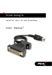
PCAN-Dongle
Parallel Port to CAN Interface
User Manual
PCAN-Dongle – User Manual
Products taken into account
Product Name
Model
Item Number
PCAN-Dongle
DIN
IPEH-002015
PCAN-Dongle
PS/2
IPEH-002019
PCAN-Dongle opto-decoupled PS/2
IPEH-002020
The cover picture shows the PCAN-Dongle opto-decoupled. The other models have a
case with silver-colored coating.
Product names mentioned in this manual may be the trademarks or registered
trademarks of their respective companies. They are not explicitly marked by “™” and
“®”.
© 2013 PEAK-System Technik GmbH
PEAK-System Technik GmbH
Otto-Roehm-Strasse 69
D-64293 Darmstadt
Germany
Phone: +49 (0)6151-8173-20
Fax:
+49 (0)6151-8173-29
www.peak-system.com
[email protected]
Issued 2013-11-18
2
PCAN-Dongle – User Manual
Contents
1
1.1
1.2
1.3
2
2.1
2.2
2.3
Introduction
4
Properties at a Glance
System Requirements
Scope of Supply
Hardware Installation
4
5
5
6
Connecting to the Computer
Connecting a CAN Bus
5-Volt Supply at the CAN Connector
6
7
7
3
Software Setup
10
4
Operation
11
4.1
4.2
4.3
4.4
Prerequisites for the Operation
Interface Information
Operating Modes
PCAN-View for Windows
11
12
14
15
5
Linking Own Programs with PCAN-Light
18
6
Frequently Asked Questions (FAQ)
19
7
Technical Specifications
20
Appendix A
CE Certificate
22
Appendix B
Quick Reference
23
3
PCAN-Dongle – User Manual
1
Introduction
Tip: At the end of this manual (Appendix B) you can find a
Quick Reference with brief information about the installation
and operation of the PCAN-Dongle.
The PCAN-Dongle allows the connection of a CAN bus to the
parallel port of a computer. Therefore the computer can easily be
integrated into a High-speed CAN network.
The opto-decoupled model of the PCAN-Dongle additionally
contains a galvanic isolation. An isolation of up to 500 V between
the computer and the CAN parts of the interface is achieved by use
of a DC/DC converter and an optocoupler.
Note: This manual refers to both the PCAN-Dongle standard
model as well as the one with galvanic isolation. Differences at
use and at the technical specifications are mentioned
accordingly in this manual.
1.1
Properties at a Glance
Connection of a High-speed CAN network (CAN specifications
2.0A and 2.0B) to a computer
Use of any parallel port that is capable of interrupts
Supports all interrupt and port address settings for the parallel
interface
Supports the standard and the ECP mode of a parallel interface
Equipped with the CAN controller SJA1000T by Philips/EXP
CAN transfer rate up to 1 MBit/s
4
PCAN-Dongle – User Manual
CAN connection 9-pin D-Sub male, pin assignment according to
CiA recommendation DS 102
Galvanic isolation up to 500 V for the CAN interface (only optodecoupled model)
Power supply (5 V) via cable with T-piece for keyboard
connector (DIN or PS/2)
Support for operating systems Windows (starting with 2000) and
Linux
Note: This manual describes the use of the PCAN-Dongle with
Windows. You can find device drivers for Linux and the
corresponding information on PEAK-System's website under
www.peak-system.com/linux.
1.2
System Requirements
The following prerequisites must be given, so that the PCAN-Dongle
can be used properly:
A free parallel port (D-Sub, 25 pins) at the computer, capable of
interrupts
Operating system Windows (Vista, XP SP2, 2000 SP4) or Linux
1.3
Scope of Supply
The scope of supply normally consists of the following parts:
PCAN-Dongle (case with two ports and a cable with T-piece for
DIN or PS/2 keyboard connector)
CD-ROM with software (drivers, utilities), programming
examples, and documentation
5
PCAN-Dongle – User Manual
2
Hardware Installation
2.1
Connecting to the Computer
1.
Make sure that the computer is turned off.
2.
Connect the PCAN-Dongle with the wider port (25 pins) to
the free parallel port at the computer.
3.
Pull the keyboard connector from the corresponding port at
the computer.
4.
Connect the T-piece at the cable of the PCAN-Dongle to the
keyboard port.
5.
Now reconnect the keyboard to the free end of the T-piece.
A configuration of the hardware is not needed. However, you
should check the settings for the parallel interface in the computer's
BIOS setup.
If the computer has a parallel interface with EPP as well as ECP
properties, the corresponding setting in the BIOS set-up should be
“ECP” (not “EPP” and not “EPP+ECP”). Although the extended
properties of the PCAN-Dongle usually will work with the lastmentioned setting some systems may have problems with it.
Therefore the setting for the “pure” ECP mode should be preferred.
Further information about the different operating modes of the
PCAN-Dongle can be found in chapter 4.3 Operating Modes on page
14.
6
PCAN-Dongle – User Manual
First Test
After turning on the computer the red LED at the PCAN-Dongle
must be permanently on. This indicates that the power supply for
the PCAN-Dongle is correct.
Attention! Don't remove PCAN-Dongle from the computer
while powered on (red LED on PCAN-Dongle is lit). Electronic
parts of the PCAN-Dongle or the computer's parallel interface
may be harmed.
2.2
Connecting a CAN Bus
A High-speed CAN bus (ISO 11898-2) is connected to the 9-pin
D-Sub port. The pin assignment corresponds to the CiA
recommendation DS 102-1.
Figure 1: Pin assignment HS-CAN
(view onto connector of the PCAN-Dongle)
2.3
5-Volt Supply at the CAN Connector
A 5-Volt supply can optionally be routed to pin 1 and/or pin 9 of the
CAN connector (PCAN-Dongle opto-decoupled: pin 1 only) by
setting solder bridges on the PCAN-Dongle PCB (Dongle case
opened). Thus devices with low power consumption (external
7
PCAN-Dongle – User Manual
transceivers or optocouplers, for example) can be directly supplied
via the CAN connector.
When using this option, the 5-Volt supply is directly connected to
the power supply of the PCAN-Dongle (coming from the computer)
and is not fused separately. The opto-decoupled model of the
Dongle contains an interconnected DC/DC converter. Therefore the
current output is limited to about 50 mA.
Attention! At this procedure special care is indispensable, since
there is a short circuit danger. The PCAN-Dongle could be destroyed and/or the power supply or electronics of the computer
or other components connected could be damaged.
Important note: PEAK-System Technik GmbH does not give
guarantee on damages which have resulted from application of
the option described in this section.
Do the following to set up a 5-Volt supply at the CAN connector:
1.
In order to access the PCB, open the case of the PCANDongle by cautiously levering the latches on both sides (risk
of breakage!), e.g. with a flat tip screwdriver.
2.
Set the solder bridges on the PCAN-Dongle PCB according
to the desired settings. Figure 2 and Figure 3 show the
possible positions of a solder bridge.
8
PCAN-Dongle – User Manual
+5 Volt at the CAN connector:
Figure 2:
PCB PCAN-Dongle (bottom view):
JP9, 2-1 (as shown) → Pin 1;
JP9, 2-3 → Pin 9
Figure 3:
PCB PCAN-Dongle opto-decoupled
(top view):
short-circuit pos. R11 → Pin 1
3.
For reassembly place the PCB overhead onto the top part of
the case. Make sure that the cable is lying in the side cut-out
with the strain relief inside the case, and that the LED is
placed in the corresponding hole of the top part of the case.
4.
Push the bottom part of the case onto the top part (the
latches click in).
9
PCAN-Dongle – User Manual
3
Software Setup
Under Windows a driver is needed that can access the PCANDongle and that provides the interface for Windows software.
Beside the mentioned device driver the CAN monitor PCAN-View
for Windows can also set up.
Do the following to setup the driver and, if applicable, additional
software:
1.
Please make sure that you are logged in as user with
administrator privileges (not needed for normal use of the
PCAN-Dongle later on).
2.
Insert the supplied CD-ROM into the drive of the computer.
Usually a navigation program appears a few moments later.
If not, start the file Intro.exe from the root directory of the
CD-ROM.
3.
Navigate through the menus to the driver installation for the
PCAN-Dongle (English > Drivers > PCAN-Dongle). Click on
Install now afterwards. The setup program for the driver is
executed. Under Windows Vista you may need to confirm
the note about the execution with elevated rights.
4.
Follow the instructions of the setup program.
10
PCAN-Dongle – User Manual
4
Operation
4.1
Prerequisites for the Operation
Under Windows you must explicitly determine the use of an
interrupt for the parallel interface. This is done in the Windows
Device Manager.
Do the following to assign an interrupt to the parallel interface
under Windows:
1.
Open the Windows Device Manager.
One way to do this is by accessing the context menu of the
desktop icon My Computer or Computer (right mouse click),
by selecting the menu item Manage, and then by selecting
the entry Device Manager from the tree view on the right.
2.
Under Ports (COM & LPT) in the tree view of the Device
Manager double click on the entry Printer Port (LPTx) or ECP
Printer Port (LPTx).
Figure 4: Entry in the Device Manager for the printer port
3.
Select the tab Port Settings.
4.
Activate the option Use any interrupt assigned to the port.
11
PCAN-Dongle – User Manual
Figure 5: Indicating the use of an interrupt
4.2
Interface Information
For the initialization of the PCAN-Dongle during the start of an
application you need information about the used interrupt and port
address of the parallel interface.
Do the following to find out the interrupt and the I/O range used
by the parallel interface:
1.
Open the Windows Device Manager.
One way to do this is by accessing the context menu of the
desktop icon My Computer or Computer (right mouse click),
by selecting the menu item Manage, and then by selecting
the entry Device Manager from the tree view on the left.
2.
Under Ports (COM & LPT) in the tree view of the Device
Manager double click on the entry Printer Port (LPTx) or ECP
Printer Port (LPTx).
12
PCAN-Dongle – User Manual
Figure 6: Entry in the Device Manager for the printer port
3.
Select the tab Resources.
4.
From the entries I/O Range (first value = port address) and
Interrupt or IRQ in the list you can see the needed
information. Write down this information for later use.
Figure 7: Resource information about the parallel interface
13
PCAN-Dongle – User Manual
4.3
Operating Modes
The PCAN-Dongle can be used in one of four possible operating
modes:
Name of Operating
Mode
Alternative
Identifier
Description
Multiplex Mode
PEAK Dongle-CAN
Standard Parallel Port (SPP)
EPP Mode
PEAK Dongle-CAN Extended Capability Port (ECP)
EPP
Multiplex PeliCAN
Mode
PEAK Dongle-CAN Standard Parallel Port (SPP),
SJA
extended CAN functionality (CAN
2.0B incl. 29-bit IDs)
EPP PeliCAN Mode
PEAK Dongle-CAN Extended Capability Port (ECP),
SJA EPP
extended CAN functionality (CAN
2.0B incl. 29-bit IDs)
The EPP PeliCAN Mode is recommended to gain the full CAN
functionality at lowest possible computer system load. If this mode
doesn't work correctly, you can fall back to one of the other
operating modes. The Multiplex Mode should work on any system.
Tip: You can find further information about the PeliCAN Mode
in the data sheet for the CAN controller SJA1000 by Philips/EXP
obtainable at the according website, for example.
You can find information about activating an operating mode in the
following section.
14
PCAN-Dongle – User Manual
4.4
PCAN-View for Windows
PCAN-View for Windows is a simple CAN monitor for viewing and
transmitting CAN messages.
Figure 8: PCAN-View main window
Installation
You can install the application optionally during the driver setup
procedure (see also chapter 3 Software Setup on page 10).
Program Start
In the Start menu of the Windows desktop you can find the entry
“PCAN Hardware”. From there you can execute the program PCANView.
A dialog for the selection of the CAN hardware as well as the setting
of the CAN parameters appears after the program start.
15
PCAN-Dongle – User Manual
Figure 9: Selection of the CAN specific parameters
If no entry is in the list “Available CAN hardware” (for example at
the first program start), you need to add one (administrator rights
needed):
1.
Press the button Add. The dialog box “Add CAN hardware”
appears.
2.
Select the connected hardware and the operating mode
from the list “Type of CAN hardware”. If the mode of the
parallel interface is set to ECP in the computer's BIOS setup,
you can register the PCAN-Dongle as “PEAK Dongle-CAN
SJA EPP”.
16
PCAN-Dongle – User Manual
Figure 10: Selection of hardware resources
3.
Enter the port address and the interrupt of the used parallel
interface established before (see section above).
4.
Confirm your input with OK.
In the dialog box “Connect to CAN hardware” make further settings
(baud rate and CAN message filter) for the created hardware entry.
If you need further help after the program start, use the online help
provided with the program (key [F1]).
17
PCAN-Dongle – User Manual
5
Linking Own Programs with
PCAN-Light
On the supplied CD-ROM you can find files that are provided for
software development. You can access them with the navigation
program (button Programming). The files exclusively serve the
linking of own programs to hardware by PEAK-System with the help
of the installed device driver under Windows.
Further more the CD-ROM contains header files and examples for
creating own applications in conjunction with the PCAN-Light
drivers. Please read the detailed documentation of the interface
(API) in each header file.
Tip: You can find further information in the file
PCANLight_enu.chm (Windows Help file) on the CD-ROM.
Notes about the License
Device drivers, the interface DLL, and further files needed for linking
are property of the PEAK-System Technik GmbH (PEAK-System)
and may be used only in connection with a hardware component
purchased from PEAK-System or one of its partners. If a CAN
hardware component of third party suppliers should be compatible
to one of PEAK-System, then you are not allowed to use or to pass
on the driver software of PEAK-System.
PEAK-System assumes no liability and no support for the PCANLight driver software and the necessary interface files. If third party
suppliers develop software based on the PCAN-Light driver and
problems occur during use of this software, please, consult the
software provider. To obtain development support, you need to
own a PCAN-Developer or PCAN-Evaluation version.
18
PCAN-Dongle – User Manual
6
Frequently Asked Questions
(FAQ)
Question
Answer
In the computer's BIOS
setup the parallel port
setting shows ECP but the
PCAN-Dongle works with
the EPP mode. Is this
correct?
Yes, it is. The naming of the
operating mode EPP of the PCANDongle has historical causes. The
parallel interface at the computer
went through various developments
in the nineties. Only the EPP
extension existed during the time,
when the PCAN-Dongle arose. With
version 1.9 the EPP extension already
had similarities to the ECP extension,
which is usually used in computers
today. The name of the operating
mode EPP was kept for the PCANDongle.
Can a printer still be
connected to the PCANDongle?
No. The PCAN-Dongle doesn't offer
any possibility to connect through the
parallel interface for the printer.
Is it possible to supply the Yes.
PCAN-Dongle PS/2 also via
the computer's mouse
connector?
I have problems running
the PCAN-Dongle under
Windows Vista/XP/2000.
The driver files PEAKCAN.SYS and
PCAN_DNG.SYS must be available at
least in version 2.30. You can
determine the currently used driver
version e.g. with the About dialog
box in PCAN-View (menu command
Help | About).
19
PCAN-Dongle – User Manual
7
Technical Specifications
Supply
Supply voltage
+5 V DC
Current consumption
PCAN-Dongle:
PCAN-Dongle opto-decoupled:
max. 80 mA
max. 140 mA
Connectors
Supply
Cable to the keyboard jack of the computer, length
about 50 cm/20 inches
Computer
D-Sub (m), 25 pins (to standard parallel port)
CAN
D-Sub (m), 9 pins
Pin assignment according to CiA recommendation
DS 102-1
IPEH-002020: galvanic isolation up to 500 V
CAN
Specification
ISO 11898-2
High-speed CAN (up to 1 MBit/s)
2.0A (standard format) and 2.0B (extended format)
Controller
Philips SJA1000T
Transceiver
Philips PCA82C251
Environment
Operating temperature
0 – 60 °C (32 – 140 °F)
Storage temperature
-20 – +80 °C (-4 – 176 °F)
Relative humidity
15 – 90 %, not condensing
EMC
EN 55024:2011-09
EN 55022:2011-12
EC directive 2004/108/EG
Continued on the next page
20
PCAN-Dongle – User Manual
Measures
Size
56 x 18 x 62 mm (2 3/16 x 11/16 x 2 7/16 Inches)
Weight
PCAN-Dongle (DIN):
52 g (1.83 oz.)
PCAN-Dongle (PS/2):
51 g (1.80 oz.)
PCAN-Dongle opto-decoupled: 52 g (1.83 oz.)
21
PCAN-Dongle – User Manual
Appendix A
CE Certificate
22
PCAN-Dongle – User Manual
Appendix B
Quick Reference
Hardware Installation
Connect the PCAN-Dongle to the computer's parallel port, insert the
T-piece at the cable's end between the keyboard port at the
computer and the keyboard connector (for power supply). When the
computer is turned on, the red LED indicates an existing power
supply.
Software setup and startup under Windows
Execute the driver installation program from the supplied CD-ROM.
Restart Windows after the setup procedure.
Run the CAN monitor PCAN-View for Windows from the Start menu
as a sample application for accessing the PCAN-Dongle. Get the
parameters of the parallel interface (I/O address, interrupt) needed
for initialization of the PCAN-Dongle from Windows' Device
Manager.
HS-CAN connector (D-Sub, 9 pins)
23