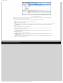
1
ASD:Suite User Manual
●
Home
●
Product
●
Technology
●
ASD:Suite User Manual
ASD:Suite Release 4 v8.5.0
TABLE OF CONTENTS
●
●
●
●
●
●
The ASD:Suite software design platform
Installation Prerequisities
Upgrading ASD models
ASD Concepts
❍ Components
❍ Models
❍ Sequence Based Specifications
❍ The ASD:Triangle and Correctness
❍ Operational semantics
■ Operational semantics of rule cases
■ Client requests
■ Notification interfaces
■ ASD Timers and the Timer Cancel Guarantee
❍ State types in a design model
❍ Used Services
The User Interface
❍ Tabs, Panes and "dockable" Windows
■ Panes and "dockable" windows
■ Meaning of colours in the SBS tab
■ The context field above each SBS
❍ Menus
■ File
■ Edit
■ View
■ Filters
■ Session
■ Verification
■ Code Generation
■ Tools
❍ Status bar
❍ State Diagram
❍ Model Navigator
❍ SBS Filters
❍ Un-saveable Data
Modelling
❍ Modelling
❍ Creating an Interface Model
■ Creating an Interface Model
■ Interfaces and Events
■ Yoking Notification Events
❍ Creating a Design Model
■ Creating a Design Model
■ Primary References
■ Sub Machines
■ State Variables for Used Service References
■ Singleton Notification Events
❍ Behaviour in an ASD Model
■ Behaviour in an ASD Model
■ State Variables
■ State Information
■ Actions
■ Target State
■ Comments
■ Tags
■ Guards
■ State Variable Updates
■ Invariants
■ Non-deterministic Behaviour
■ Adding or deleting a rule case
■ Inserting or replacing rule cases
❍ Parameters
■ Parameters
■ Parameter Declaration
■ Parameter Usage
■ Example of Parameter Passing
❍ Tags
❍ Broadcasting Notifications
❍ Construction Parameters
■ Construction Parameters
■ Passing parameters
■ Passing an instance of a used component
■ Passing a vector of instances
■ Passing a shared instance
■ Passing a primary reference
❍ Refactoring ASD Models
■ Refactoring ASD Models
■ Changing the Initial State for an SBS
■ Duplicate a State
■ Moving Events to a Different Interface
■ Deleting Events or Interfaces
■ Renaming Events or Interfaces
■ Changing Event Parameters
■ Changing the Order of Events or Interfaces
■ Replacing an Interface Model
http://community.verum.com/documentation/user_manual_pdf.aspx/8.5.0/toc (1 of 2) [03/12/2012 09:30:41]
Resources
●
Training
●
Purchase
●
Company
ASD:Suite User Manual
❍
●
●
●
●
●
Save As
Conflicts
❍ Conflicts
❍ Fixing conflicts
❍ Fixing IM-DM difference conflicts
❍ Fixing syntax related conflicts
❍ Fixing name duplicates
❍ Fixing interface related conflicts
❍ Fixing argument, parameter or component variable related conflicts
❍ Fixing used service references related conflicts
❍ Fixing rule case related conflicts
❍ Fixing state variable and guard related conflicts
❍ Fixing other conflicts
Verification
Code Generation
❍ Code Generation
❍ Preparing the ASD model for code generation
■ Preparing the ASD model for code generation
■ Specifying the component type
■ Specifying the execution model
■ Specifying a target language and the code generator version
■ Defining construction parameters
■ Specifying output path and attribute code with tracing information
■ Ensuring correct referencing of user defined types
■ Specifying path to user provided text for code customization
■ Serialising ASD components
❍ Generating code from an ASD model
❍ Generating stub code from an ASD interface model
❍ Downloading the ASD Runtime
Session Management
❍ Session Management
❍ Logging In
❍ Saving Connection Settings
❍ Long-latency Connections
Command-line tools
❍ Command-line tools
❍ ASD:Suite Commandline Client
❍ ASD:ModelConverter
❍ ASD:SetModelProperties
❍ ASD:Suite ModelCompare
© 2012 Verum Software Technologies B.V. All rights reserved
Terms of use | Privacy Policy
http://community.verum.com/documentation/user_manual_pdf.aspx/8.5.0/toc (2 of 2) [03/12/2012 09:30:41]
ASD:Suite User Manual
●
Home
●
Product
●
Technology
●
Resources
●
Training
●
Purchase
●
Company
The ASD:Suite software design platform
User Manual
ASD:Suite Release 4 v8.5.0
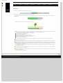
The ASD:Suite is a software design (CAD) platform based upon Verum's patented Analytical Software Design (ASD) technology. ASD
makes it possible to create systems from mathematically verified components.
The ASD:Suite is used to define and (automatically) verify models, and to (automatically) generate fully executable source code from
these models. The models specify both structure and behaviour of services, and of components that implement and use these
services. See the "ASD Concepts" section for details.
See "How to set up the ASD:Suite" for guidelines about installing and setting up the ASD:Suite.
Note: Starting with the ASD:Suite Release 3 v7.2.0 you have the possibility to install the ASD:Suite ModelCompare, a feature that
allows you to find and eliminate differences between two versions of an ASD model or between two related or unrelated ASD models.
The set of User Manuals for the ASD:Suite consists of:
●
The ASD:Suite Release Notes (see archive for latest and older versions).
●
The ASD:Suite User Manual (this document; see archive for older versions).
●
The ASD:Suite ModelCompare User Guide (see archive for latest and older versions).
●
The ASD:Suite Visual Verification Guide (see archive for latest and older versions).
●
The ASD Runtime Guide (see archive for latest and older versions).
A simple Alarm system example, consisting of a set of interface models and design models together with the related source code can
be downloaded from here. This is a fully executable system that can be built using Visual Studio (for C++ and C#) and Eclipse (for
Java).
To uninstall the ASD:Suite Release 4 v8.5.0 use the "Start -> All Programs -> ASD Suite Release 4 V8.5.0 -> Uninstall" item.
Copyright (c) 2008 - 2012 Verum Software Technologies B.V.
ASD is licensed under EU Patent 1749264 and Hong Kong Patent HK1104100
All rights are reserved. No part of this publication may be reproduced in any form or by any means, electronic, mechanical,
photocopying, recording, or otherwise, without the prior written permission of the copyright owner.
© 2012 Verum Software Technologies B.V. All rights reserved
Terms of use | Privacy Policy
http://community.verum.com/documentation/user_manual_pdf.aspx/8.5.0/overview [03/12/2012 09:30:45]
ASD:Suite User Manual
●
Home
●
Product
●
Technology
●
Resources
●
Training
●
Purchase
●
Company
ASD:Suite Release 4 v8.5.0
Installation Prerequisities
The ASD:Suite client-side software is developed specifically for the Microsoft Windows platform and is guaranteed compatible with
the versions (including correction packages) as specified below:
●
Microsoft Windows XP, Service Pack 3
●
Microsoft Windows 7, Service Pack 1
Supported Programming Languages and Compilers
The supported compilers for the various programming languages are specified below:
●
For C++ see "Supported compilers and boost versions for C++"
●
For C# see "Supported compilers and execution platforms for C#"
●
For C see "Supported compilers and execution platforms for C"
●
For Java see "Supported compilers and execution platforms for Java"
3rd Party Dependencies
The ASD:Suite includes software developed by the following parties:
●
Boost.org : "Boost Software License"
●
The OpenSSL Project & Cryptsoft : "OpenSSL License and Original SSLeay License"
●
Arabica - XML Parser Library : "Arabica XML and HTML Processing Toolkit License"
●
The Expat XML Parser : "Expat License"
●
The libexecstream library : "The libexecstream library license"
●
Apache Xerces C++ - XML Parser Library : "Apache License, Version 2.0"
●
Graphviz - Graph Visualization Software : "The Eclipse Public License - v 1.0"
●
XZip : "XZip original author comments"
© 2012 Verum Software Technologies B.V. All rights reserved
Terms of use | Privacy Policy
http://community.verum.com/documentation/user_manual_pdf.aspx/8.5.0/prerequisites_compilers_3rdparty [03/12/2012 09:30:48]
ASD:Suite User Manual
●
Home
●
Product
●
Technology
●
Resources
●
Training
●
Purchase
●
Company
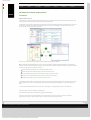
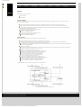
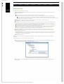
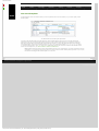
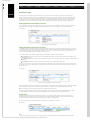
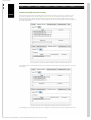
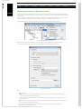
Upgrading ASD models
The ASD:Suite provides the possibility to automatically upgrade ASD models which were built using a previous major release of the
ASD:Suite.
Note: The major release is indicated as the first number out of the three indicating the version of the released ASD:Suite.
Tip: Use the "File->Upgrade Models..." menu item if you want to upgrade all the models located in a folder and its sub-folders.
Tip: If you need to set a new code generator version for multiple models, you can use the ASD:SetModelProperties command-line
tool.
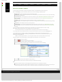
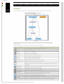
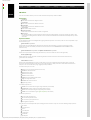
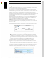
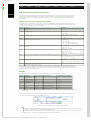
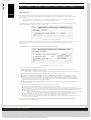
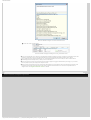
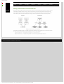
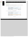
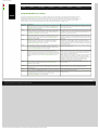
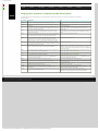
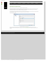
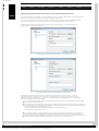
The following figure shows the dialog you see when you open a model of an older major version:
Upgrade dialog
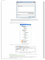
The following table shows the effect of choosing one out of the four options presented above in case of an interface model:
Operation
Model upgraded
Model saved
Upgrade
Yes
Yes
View Only
Yes
No
Upgrade All
Yes
Yes
Cancel
No
No
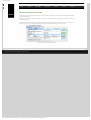
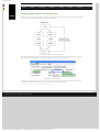
The following table shows the effect of choosing one out of the three options presented above in case of a design model:
Operation
Design Model
Related Interface Models
upgraded
saved
upgraded
saved
Upgrade
Yes
Yes
Yes
No
View Only
Yes
No
Yes
No
Upgrade All
Yes
Yes
Yes
Yes
Cancel
No
No
No
No
© 2012 Verum Software Technologies B.V. All rights reserved
Terms of use | Privacy Policy
http://community.verum.com/documentation/user_manual_pdf.aspx/8.5.0/upgrade [03/12/2012 09:30:51]
ASD:Suite User Manual
●
Home
●
Product
●
Technology
●
Resources
●
Training
●
Purchase
●
Company
ASD concepts
Components
ASD is a component-based technology in which systems are composed of a mixture of ASD components and Foreign components.
Within ASD, a component is a common unit of architectural decomposition, specification, design, mathematical verification, code
generation and runtime execution.
ASD components
ASD components are software components that are specified and designed using ASD. An interface model specifies the externally
visible behaviour of a component. A design model specifies its inner working and how it interacts with other components. All ASD
components must have both an interface model and a design model.
ASD components are mathematically verified. In the ASD:Suite this is done using a Software as a Service (SaaS) application. The
necessary mathematical models are generated automatically from both design and interface models. The source code to implement
an ASD component is generated automatically from its design model.
Foreign components
Foreign components are hardware or software components of a system which are not developed using ASD. As they have to be used
by ASD components, they must correctly interface and interact with them. They may be third party components, legacy code or
handwritten components representing those parts of a system that cannot be generated from ASD designs. All used foreign
components must have an interface model which specifies the externally visible behaviour of the component. Foreign components
do not have a corresponding design model.
The interface model of foreign components is used for two purposes:
1. For verifying ASD components that use these foreign components: formal models are generated automatically from the
interface models. They are used to verify that an ASD component interacts correctly at runtime with the corresponding
foreign component.
2. For code generation: to generate the correct interface header files.
Note: The handwritten implementation provided for the foreign component must correctly implement all methods declared in the
generated interface header files. This includes ASD specific methods like GetInstance, ReleaseInstance, GetAPI, and RegisterCB.
© 2012 Verum Software Technologies B.V. All rights reserved
Terms of use | Privacy Policy
http://community.verum.com/documentation/user_manual_pdf.aspx/8.5.0/concepts/components [03/12/2012 09:30:54]
ASD:Suite User Manual
●
Home
●
Product
●
Technology
●
Resources
●
Training
●
Purchase
●
Company
Models
ASD supports two types of models:
●
Interface Model
●
Design Model
Interface Model
An interface model is a model of the externally visible behaviour of an ASD component or Foreign component, i.e. the service that
the component implements.
●
It identifies the component's application interfaces and notification interfaces and specifies their associated events.
●
It specifies the externally visible behavioural semantics of the component in the form of one Sequence-Based Specification.
●
●
●
It may also specify modelling interfaces with associated events that are hidden from the client and are used to represent hidden
internal behaviour of the implementation.
The triggers in an interface model are occurrences of:
❍ Call events on application interfaces;
❍ Events on modelling interfaces.
The actions in an interface model are occurrences of:
❍ Reply events on application interfaces;
❍ Events on notification interfaces.
Design Model
A design model is a model of the internal behaviour of an ASD component.
●
●
●
●
●
Its implemented service and used services are specified by interface models;
It fully and deterministically specifies the internal logic of the component as one or more Sequence-Based Specifications;
❍ A simple design is represented by a single Sequence-Based Specification;
❍ A complex design is partitioned hierarchically into a main machine and one or more sub machines. Each of these is specified by a
Sequence-Based Specification.
If the design is partitioned:
❍ There is one transfer interface defined for each sub machine through which the main machine and sub machine communicate.
❍ Transfer interfaces are not visible to clients or servers.
The triggers in a design model are occurrences of:
❍ Call events on application interfaces of the implemented service;
❍ Reply events on the application interfaces of the used services;
❍ Events on the notification interfaces of the used services;
❍ For a main machine, reply events on transfer interfaces;
❍ For a sub machine, call events on its transfer interface.
The actions in a design model are occurrences of:
❍ Call events on application interfaces of the used services;
❍ Reply events on application interfaces of the implemented service;
❍ Events on notification interfaces of the implemented service;
❍ For a main machine, call events on transfer interfaces;
❍ For a sub machine, reply events on its transfer interface.
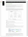
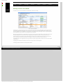
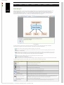
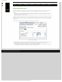
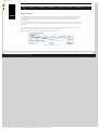
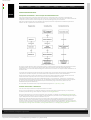
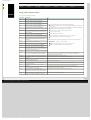
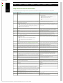
The following figure shows the various types of events in a design model:
The various types of events in a design model
© 2012 Verum Software Technologies B.V. All rights reserved
Terms of use | Privacy Policy
http://community.verum.com/documentation/user_manual_pdf.aspx/8.5.0/concepts/models [03/12/2012 09:30:57]
ASD:Suite User Manual
●
Home
●
Product
●
Technology
●
Resources
●
Training
●
Purchase
●
Company
Sequence Based Specifications
According to the IEEE Standard Glossary of Software Engineering Terminology, a specification is a complete, precise and verifiable
description of the characteristics of a system or a component. Within ASD the distinction between an interface specification
(interface model) and a design specification (design model) is fundamental.
The interface model describes the externally visible behaviour of a component and is as implementation-free as possible. This means
that the model defines what the component does under every circumstance but not how the component will do it. The external
behaviour is specified independently of any specific implementation. It is an abstraction of the component or system
implementation that every compliant design is required to implement.
The design model describes the internal behaviour of a component. It rigorously and completely defines one of the many possible
implementations that faithfully comply with the interface model.
An ASD component implements a service (specified by the interface model) that is used by its clients. This implemented service is
exposed by means of application interfaces through which clients can send call events. The ASD component can respond to a call
event on an application interface by means of a reply event on the same application interface and events on notification interfaces.
In this process, an ASD component can also invoke used services that are implemented by other components: the servers of the ASD
component. Collectively, the services between a component and its clients and servers form an imaginary border, called the
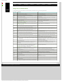
component boundary. Information crosses the component boundary in the form of events.
Component boundary
A component "knows" only information passed into it across the component boundary in the form of the triggers it receives. A
trigger can be:
●
A call event from a client through an application interface;
●
A reply event from a server through an application interface;
●
A notification event from a server through a notification interface.
Similarly, a component exposes information to its clients and servers across the component boundary in the form of the actions it
sends. An action can be:
●
A call event to a server through an application interface;
●
A reply event to a client through an application interface;
●
A notification event to a client through a notification interface.
An interface model is defined in terms of only those events that pass between a component and its Clients. A design model is defined
in terms of events that pass between the component, its Clients and its Servers.
Within ASD, both interface models and design models are defined in the form of Sequence-Based Specifications (SBS). Behaviour is
specified in a tabular form as a total Black Box function, by mapping all possible sequences of triggers to the corresponding actions.
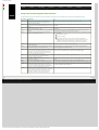
The following figure shows an SBS specified in the ASD:Suite:
An SBS in the ASD:Suite
The method used to create these specifications, is called Sequence Enumeration. This requires the systematic enumeration of all
possible input sequences of triggers, ordered by length, starting with the empty sequence. Triggers can be repeated within a
sequence and since sequence length is not restricted, the set of all possible sequences is infinite. In practice, systems do not display
an infinite set of unique, non-repeating behaviours. They cycle through a finite set of states and repeat a finite set of behaviours.
Thus the infinite set of input sequences of triggers can be reduced to a finite set of equivalence classes.
Each class is identified by a minimal length sequence, called Canonical Sequence. All sequences in a given equivalence class have the
same future system behaviour. They are said to be Mealy Equivalent. The equivalence classes form the set of states in a Mealy
http://community.verum.com/documentation/user_manual_pdf.aspx/8.5.0/concepts/sbs (1 of 2) [03/12/2012 09:31:01]
ASD:Suite User Manual
Machine.
The theory underlying this approach tells us that by reasoning about the behaviour of the finite set of Canonical Sequences, we can
reason about the behaviour of every possible input sequence. The Sequence Enumeration method used in ASD thus defines the Black
Box function as a total function between the finite set of Canonical Sequences and the corresponding actions.
© 2012 Verum Software Technologies B.V. All rights reserved
Terms of use | Privacy Policy
http://community.verum.com/documentation/user_manual_pdf.aspx/8.5.0/concepts/sbs (2 of 2) [03/12/2012 09:31:01]
ASD:Suite User Manual
●
Home
●
Product
●
Technology
●
Resources
●
Training
●
Purchase
●
Company
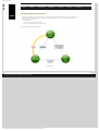
The ASD Triangle and Correctness
Architects and designers can use the ASD:Suite to create models of software components, verify their completeness and
(behavioural) correctness, and generate source code from verified design models. At its core, ASD guarantees the
(mathematical) equivalence of:
1. An ASD model;
2. A formal representation of that model;
3. The source code generated from the ASD model.
This equivalence is called the ASD Triangle:
The ASD Triangle
© 2012 Verum Software Technologies B.V. All rights reserved
Terms of use | Privacy Policy
http://community.verum.com/documentation/user_manual_pdf.aspx/8.5.0/concepts/triangle [03/12/2012 09:31:04]
ASD:Suite User Manual
●
Home
●
Product
●
Technology
●
Resources
●
Training
●
Purchase
●
Company
Operational semantics of rule cases
At runtime, a single detail row (a rule case) is interpreted as follows:
●
●
When the trigger occurs and the guard evaluates to "true" (or is omitted), then, as a single atomic action, all of the following occur:
❍ The actions are executed in the order in which they are specified in the "Actions" column
❍ The state variable updates are performed (using simultaneous assignment semantics)
❍ The state transition takes place.
If an action is defined as "valued", i.e. one that gives back a synchronous reply, it must be the last action in the sequence of actions.
The reply is processed as a trigger that occurs after the state transition has taken place.
The following figure shows a set of rule cases specified in an SBS:
© 2012 Verum Software Technologies B.V. All rights reserved
Terms of use | Privacy Policy
http://community.verum.com/documentation/user_manu...px/8.5.0/concepts/operational_semantics/rule_cases [03/12/2012 09:31:07]
ASD:Suite User Manual
●
Home
●
Product
●
Technology
●
Resources
●
Training
●
Purchase
●
Company
Client requests
●
●
●
●
●
●
All triggers on the Client Application Interface are implemented as method calls.
When an Application Interface trigger is executed, the execution takes place under the context of the Client's thread and the Client
code thus can't be executed until the synchronous call returns.
The response to the Client trigger, and thus its return to the client caller, takes place when the component issues an action on the
Client Application Interface. Until this occurs, the Client remains synchronously blocked.
A trigger implemented as a "void" method takes a "VoidReply" action as a signal to return to the Client.
A trigger implemented as a method returning a synchronous reply value, requires the corresponding action in order for the Client
to continue execution.
While the Client is blocked, the component can continue receiving notifications but it can not receive any other trigger from any
Client thread via any of its Client Application Interfaces. As seen by its Clients, an ASD component has Monitor semantics.
© 2012 Verum Software Technologies B.V. All rights reserved
Terms of use | Privacy Policy
http://community.verum.com/documentation/user_manua....5.0/concepts/operational_semantics/client_requests [03/12/2012 09:31:10]
ASD:Suite User Manual
●
Home
●
Product
●
Technology
●
Resources
●
Training
●
Purchase
●
Company
Notification interfaces
●
Notification interfaces exist to provide notifications to Clients.
●
Notification interfaces are implemented by the Client.
●
●
●
●
Circular control dependencies that occur when independent ASD components are composed into a system may cause deadlocks.
To prevent these, notifications are decoupled via a queue and a separate thread called the DPC Server Thread.
An action which maps onto a notification interface is always non-blocking.
Every ASD component which uses a service with at least one notification interface will automatically include a DPC Server Thread
and the decoupled calling mechanism.
All notifications are "void" events. They can have parameters, if required.
© 2012 Verum Software Technologies B.V. All rights reserved
Terms of use | Privacy Policy
http://community.verum.com/documentation/user_manua.../8.5.0/concepts/operational_semantics/notifications [03/12/2012 09:31:13]
ASD:Suite User Manual
●
Home
●
Product
●
Technology
●
Resources
●
Training
●
Purchase
●
Company
ASD Timers and the Timer Cancel Guarantee
●
ASD components can make use of the ASD Timer service by instantiating as many Timers as they need. To instantiate a Timer you
have to specify the ITimer model as a used service in the design model of the ASD component and you have to specify the
desired instances of the respective service.
Note:
❍ The ITimer interface model which needs to be specified as a used component is delivered as part of the ASD Runtime.
❍ You must select all Application Interfaces and Notification Interfaces defined in ITimer.im as "Used Interfaces" (for details see
"Specify connected interfaces"). If you do not do so an error will be reported when you try to verify the model or generate code.
❍ The ASD timer is a special used service that can not be shared among component designs, i.e. one component can not use the ITimer
application interface of a timer component while another component uses the ITimerCB notification interface of the same timer
component.
❍ The ITimer model must not be changed. Any attempt to do so breaks the correctness guarantee provided by the ASD:Suite.
❍ You should not generate code from the ITimer.im file and you do not have to make a design for the timer component. The
implementation is provided in the ASD Runtime.
●
●
ASD Timers implement the CreateTimer, CreateTimerMSec and CreateTimerEx triggers to start the timer for a specified duration
in seconds, milliseconds, or seconds and nanoseconds, respectively. Timer completion is signalled via the TimeOut notification event.
All ASD Timers support a CancelTimer trigger. The ASD Runtime guarantees that once a timer has been cancelled, the TimeOut
trigger will never occur, not even if the timer has actually expired and the TimeOut event is waiting in the queue to be processed by
the DPC.
© 2012 Verum Software Technologies B.V. All rights reserved
Terms of use | Privacy Policy
http://community.verum.com/documentation/user_manu...f.aspx/8.5.0/concepts/operational_semantics/timers [03/12/2012 09:31:16]
ASD:Suite User Manual
●
Home
●
Product
●
Technology
●
Resources
●
Training
●
Purchase
●
Company
State types in a design model
Within a design model four types of state are distinguished:
●
●
●
●
●
Initial state in the main machine. This is the state in the main machine where the component starts after construction. The inital state
is a "Normal state", and any Normal State can be made Initial State.
Super state. These are states in the main machine in which a sub machine is active. In these Super-states, all triggers must have
"Blocked" as associated action except for the transfer reply events that correspond to the active sub machine.
Initial state in a sub machine. This is the state in which the sub machine is not active (i.e. the main machine is not in the corresponding
Super state). In the Initial states of a sub machine, all triggers must have "Blocked" as associated action except for the transfer call
events that correspond to this sub machine.
Synchronous return state. These are states following a valued action, where the design is waiting for a valued reply from the called
used service (note that these synchronous return states may exist in the main machine as well as in a sub machine). In these
Synchronous return states, triggers must have "Blocked" as associated action except for the application reply events that correspond
with the called used service.
Normal state. These are all other states. In these states NONE of the external triggers (i.e. implemented service application call events
and used service notification events) may have a "Blocked" action. If no action is allowed or possible for these triggers in a normal
state, the action must be set to "Illegal". For example, when the application interface is "closed" (the Client is waiting for a reply to an
application call event). On the other hand, all application reply events and transfer reply events must have a "Blocked" action in
a normal state, since there is no application call event to a used service active, nor is there any sub machine active.
© 2012 Verum Software Technologies B.V. All rights reserved
Terms of use | Privacy Policy
http://community.verum.com/documentation/user_manual_pdf.aspx/8.5.0/concepts/state_types [03/12/2012 09:31:19]
ASD:Suite User Manual
●
Home
●
Product
●
Technology
●
Resources
●
Training
●
Purchase
●
Company
Used Services
A design model can use instances of other services. In ASD, service instances are always represented by means of Used
Service References which are sequences of used service instances. Within each used service reference, instances are
numbered starting from 1.
The set of all component instances that are used in a design model is determined by the primary references. Each primary reference
is defined by:
1. a name,
2. a number of component instances,
3. an interface model that specifies the behaviour of the used service,
4. the interfaces of the used service that the component is connected with,
5. a component name (either an ASD component or Foreign component) that specifies the service instance's internal behaviour or a
use statement to inject a component. See "Primary References" for details.
Primary references can be grouped together into secondary references. Note: secondary references are deprecated and will
be removed in the next major ASD:Suite release. In contrast with primary references, secondary references can contain instances
of different components, as long as the components implement the same service.
The primary and secondary references determine the grouping of rule cases. Triggers coming from used service instances that are
part of secondary references are all processed by the same set of rule cases. The same goes for the set of service instances that are
part of a primary reference that is not part of a secondary reference.
Used service references can be used to send an event to multiple service instances at once. The actions are sent to the used
service instances in the order that the services instances have in the used service reference.
Used service reference state variables are service references whose contents can change dynamically. They can be used in
guards, actions and state variable updates. See "State Variables for Used Service References" for details.
By construction, primary references can not include the same service instance multiple times (under the assumption that
the components are "multiples", see "Specifying component type" for details). State variables can however contain the same
instance multiple times, which in principle could be used to send the same action multiple times to the same service instance.
© 2012 Verum Software Technologies B.V. All rights reserved
Terms of use | Privacy Policy
http://community.verum.com/documentation/user_manual_pdf.aspx/8.5.0/concepts/used_services [03/12/2012 09:31:22]
ASD:Suite User Manual
●
Home
●
Product
●
Technology
●
Resources
●
Training
●
Purchase
●
Company
Panes and "dockable" windows
The main window of the ASD:Suite, also referred as the Master window, is by default filled in by the Start Page pane.
Next to the Start Page you can load in the Master window one or more of the following "dockable" windows:
●
●
●
●
●
●
"Model Explorer", used to display the structure of the loaded ASD models.
"Model Editor", used to view or edit an ASD model. There is a model editor per loaded ASD model, which you open by double-clicking
the model in the Model Explorer.
"Verification Results", used to display the set of checks for verification. See the "ASD:Suite Visual Verification User Guide" for details.
"Visual Verification", used to display the information needed to fix the failed checks. See the "ASD:Suite Visual Verification User
Guide" for details.
"Conflicts", used to display messages associated to specification conflicts. See "Conflicts" for details.
"Output Window", used to display the progress of certain time consuming operations, like loading of an ASD model and/or generating
code.
●
"Find Results", used to display the results of a "Find All" operation.
●
"Model Navigator", used to visualize the relationships between ASD models in a given directory. See "Model Navigator" for details.
●
"Un-saveable Data", which shows syntactically incorrect table cells that cannot be stored into the model file. See "Un-saveable Data"
for details.
You can drag dockable windows (like the Output Window or Model Editor) out of the Master Window to create a so-called
Slave Window. Multiple dockable windows can be dragged into the same Slave Window.
Tip: double-click the title bar of a dockable window to automatically undock it and create a new slave window.
You can drag or load as many "dockable" windows in an already created slave window, but you can not have a Start Page pane in it.
You can change the layout of a (Master or Slave) window by dragging the "dockable" windows around by their title bar to
various places in the respective window. If you drag a "dockable" window to another window, it will remember the place it last had
in that window and dock itself there.
Note: You can NOT drag Slave windows - you need to grab the title bar of the contained "dockable" window instead.
Empty Slave windows are closed automatically. The following list reflects alternatives to close a slave window:
●
Select the Slave window and press Alt+F4
●
Press the
●
Drag and drop all its "dockable" windows in the Master window or in an other Slave window
●
Close all windows docked in the Slave window. A dockable window can be closed by one of the following:
❍
Press the X button in the blue window title bar,
button in the top-right corner of the window
Dockable windows in a Slave window
❍
Press the
❍
Deselect the item in the View menu of the Slave window (not for Model Editor windows).
button if the window is tabbed in the Slave window, or
Note:
●
●
The Master and Slave windows are normal application windows that can be a.o. minimized and maximized.
The window layout, the location of Master and Slave window(s) on the screen, is remembered per screen setup. This means that if you
switch from single to dual screen setup, you have to reorder your windows to accomodate for the dual screen setup.
© 2012 Verum Software Technologies B.V. All rights reserved
Terms of use | Privacy Policy
http://community.verum.com/documentation/user_manu...8.5.0/user_interface/tabs_panes_windows/tabs_intro [03/12/2012 09:31:25]
ASD:Suite User Manual
●
Home
●
Product
●
Technology
●
Resources
●
Training
●
Purchase
●
Company
Meaning of colours in the SBS tab
The various colours used in the SBS tab of the "Model Editor" each have a meaning.
Colours used in the SBS tab
The blue, grey or orange rows indicate a state. The rows under a state row list all the possible triggers to the component and the
corresponding actions when the triggers occur in that state. The orange row in the previous figure indicates a "floating" state.
These are states that are not reachable from the initial state. In the example above, the EntryError state is not present anywhere
in the "Target State" column, and thus is not reachable from the initial state.
Blue states are Normal States or the Initial State. Grey states are either Synchronous Return States or Super States. Orange states
are either floating (there are no transitions to it) or ambiguous (there are both valued and non-valued transitions to it).
The green cells in the "Target State" column indicate that the respective rule case defines the first transition to that particular
state. This identifies the shortest possible sequence of triggers to that particular state (the canonical sequence).
The light-blue cells in the "Target State" column (e.g. line 33 in the previous figure) indicate a transition to the same state (called
"self-transition").
The light-grey line indicates the currently "active" rule case (e.g. line 32 in the previous figure).
The dark-grey cell/line indicates the currently selected cell/line.
© 2012 Verum Software Technologies B.V. All rights reserved
Terms of use | Privacy Policy
http://community.verum.com/documentation/user_manu....5.0/user_interface/tabs_panes_windows/sbs_colours [03/12/2012 09:31:29]
ASD:Suite User Manual
●
Home
●
Product
●
Technology
●
Resources
●
Training
●
Purchase
●
Company
The context field above each SBS
The ASD:Suite provides detailed information about a selected field in the SBS tab in an information (non-editable) field located
just above the SBS table.
The left part of the context field shows the state to which the currently selected rule case belongs. This is handy if the state row
is scrolled out-of-view.
The right part of the context field shows extra information about the currently selected cell. For instance, if you select a cell in
the "Event" column, it shows the event declaration including the parameter directions and parameter types.
The Context information field in the SBS tab
© 2012 Verum Software Technologies B.V. All rights reserved
Terms of use | Privacy Policy
http://community.verum.com/documentation/user_manu....0/user_interface/tabs_panes_windows/context_field [03/12/2012 09:31:32]
ASD:Suite User Manual
●
Home
●
Product
●
Technology
Resources
●
●
Training
●
Purchase
●
Company
The File menu
New
Menu Item
Open
Add Model(s)
Save
Save <model_name> As...
Save to .zip file
E-mail model
Close Model
Close All
Print
Open in Model Navigator
Properties
Purpose
Create a new ASD model.
See "Creating an Interface Model" or "Creating a Design Model" for details.
Open an ASD model or a model verification results file, closing the current model(s).
Load more models (read-only) into the ModelBuilder, without replacing the existing ones.
Save the current ASD model.
Save an exact copy of the currently selected model or to create a new model based on the
current one.
See "Save As" for details.
Save the main model (and related IMs if it is a design model) to a .zip file.
Starts your default e-mail client and attaches a .zip file with the main model and any related
IMs. Note that you need a configured e-mail program to use this.
Close the selected model.
Close all models.
Print (parts of) the current ASD model.
Open the map in which the selected model occurs.
See "Model Navigator" for details.
Open the Properties dialog of the active model.
Note: This dialog is used for specification of properties to be used in verification and
code generation.
Open in ASD:Suite ModelCompare
Open the current model in the ASD:Suite ModelCompare tool, so you can compare it to
another (version of the) model.
Note:
●
●
Open in a new instance of ASD:Suite ModelBuilder
Open in this instance of ASD:Suite ModelBuilder
Upgrade Models
Exit
The selected model is loaded as the Master.
This option is greyed out (disabled) if the ASD:Suite ModelCompare is not installed or
there is no ASD model loaded.
See the "ASD:Suite ModelCompare User Guide" for details.
Open the selected model in a new instance of the ASD:Suite ModelBuilder.
Set this model as the main model.
Upgrade models made with older versions of ASD:Suite to the current version.
See "Upgrading ASD models" for details.
Exit the application.
Note: In addition to the presented items in the File menu you will see a list of recently opened models. You can set the
maximum number of models to be listed by specifying the size of the recent models list in the Options dialog obtained via
"Tools-->Options" under the "Appearance" tab.
© 2012 Verum Software Technologies B.V. All rights reserved
Terms of use | Privacy Policy
http://community.verum.com/documentation/user_manual_pdf.aspx/8.5.0/user_interface/menus/file [03/12/2012 09:31:35]
ASD:Suite User Manual
●
Home
●
Product
●
Technology
●
Resources
●
Training
●
Purchase
●
Company
The Edit menu
Menu Item
Undo
Redo
Find
Replace
Clear Find Results
Purpose
Undo an action.
Redo an undone action.
Search for text in (part of) the ASD model.
Replace text in (part of) the ASD model.
Clear the Find Results table and the green highligting after a Find All.
© 2012 Verum Software Technologies B.V. All rights reserved
Terms of use | Privacy Policy
http://community.verum.com/documentation/user_manual_pdf.aspx/8.5.0/user_interface/menus/edit [03/12/2012 09:31:38]
ASD:Suite User Manual
●
Home
●
Product
●
Technology
●
Resources
●
Training
●
Purchase
●
Company
The View menu
Menu Item
Toolbars
Model Explorer
Output Window
Conflicts
Find Results
Verification Results
Visual Verification
Un-saveable Data
Model Navigator
Purpose
Show/hide each of the toolbars
Open or close the "Model Explorer", which shows all loaded models.
Open or close the "Output Window", which shows status and progress.
Open or close the "Conflicts" window, showing specification conflicts.
See "Conflicts" for details.
Open or close the "Find Results" window, showing the results of a Find All operation.
Open or close the "Verification Results" window, which shows the progress and results of verifying a model.
See "Verification" for details.
Open or close the "Visual Verification" window, which shows information about the current verification error in the model.
See "Verification" for details.
Open or close the "Un-saveable Data" window.
See "Un-saveable Data" for details.
Open or close the "Model Navigator" window, which shows the relationships between ASD models in a given directory.
See "Model Navigator" for details.
© 2012 Verum Software Technologies B.V. All rights reserved
Terms of use | Privacy Policy
http://community.verum.com/documentation/user_manual_pdf.aspx/8.5.0/user_interface/menus/view [03/12/2012 09:31:41]
ASD:Suite User Manual
●
Home
●
Product
●
Technology
●
Resources
●
Training
●
Purchase
●
Company
The Filters menu
Menu Item
Hide Illegal
Hide Blocked
Hide Disabled
Hide Invariant
Hide Self Transitions
Filter by text
Toggle Expression/Text Mode
Jump to Expression Edit
Expression Builder
Filtering Help...
Turn All Filters Off
Apply Filters
Purpose
Hide all rule cases that have "Illegal" as only action.
See "SBS Filters" for details.
Hide all rule cases that have "Blocked" as only action.
See "SBS Filters" for details.
Hide all rule cases that have "Disabled" as only action.
See "SBS Filters" for details.
Hide all Invariant rule cases.
See "SBS Filters" for details.
Hide all rule cases that have their own state as Target State.
See "SBS Filters" for details.
Show only rule cases having the text in the edit box in the filtering toolbar.
See "SBS Filters" for details.
Switch between interpreting the text in the filtering toolbar edit as basic text or as an expression.
See "SBS Filters" for details.
Set keyboard focus to the filtering edit box in the toolbar.
See "SBS Filters" for details.
Show a dialog to help defining an expression to filter on.
See "SBS Filters" for details.
Show this help page: "SBS Filters".
Show all rule cases.
See "SBS Filters" for details.
Re-apply all filters to the SBS.
See "SBS Filters" for details.
© 2012 Verum Software Technologies B.V. All rights reserved
Terms of use | Privacy Policy
http://community.verum.com/documentation/user_manual_pdf.aspx/8.5.0/user_interface/menus/filters [03/12/2012 09:31:44]
ASD:Suite User Manual
●
Home
●
Product
●
Technology
●
Resources
●
Training
●
Purchase
●
Company
The Session menu
Menu Item
Connection Status
Log Out
Store Login Settings...
Delete Login Settings...
Purpose
Show details about the connection to the ASD:Server.
See "Session Management" for details.
Stop the active session with the ASD:Server.
See "Session Management" for details.
Store the current login settings to the registry for easy switching between different settings.
See "Saving Connection Settings" for details.
Removes previously stored login settings from the registry.
See "Saving Connection Settings" for details.
© 2012 Verum Software Technologies B.V. All rights reserved
Terms of use | Privacy Policy
http://community.verum.com/documentation/user_manual_pdf.aspx/8.5.0/user_interface/menus/session [03/12/2012 09:31:47]
ASD:Suite User Manual
●
Home
●
Product
●
Technology
●
Resources
●
Training
●
Purchase
●
Company
The Verification menu
Verify...
Menu Item
Verify With...
Verify All
Verify Again
Open Verification Results
Stop Verifying
Show Previous Failure
Show Next Failure
Forward Step Over
Forward Step Into
Forward Step Out
Forward Step Rule Case
Backward Step Over
Backward Step Into
Backward Step Out
Backward Step Rule Case
Step To First
Step To Last
Purpose
Verify the selected ASD model.
See "Verification" for details.
Same as Verify, but this asks you for a code generator version and language.
Note: use with great care; if the generated code is created using a different version than the version with which the
model is verified, there is no guarantee that the generated code will be error-free.
Run all checks for the selected ASD model.
See "Verification" for details.
Re-run the last verification.
See "Verification" for details.
Open a model verification results file, containing the details of an model verification that was performed earlier.
Abort a verification.
Show in the Visual Verification window the first example of the previous failed check.
Show in the Visual Verification window the first example of the next failed check.
Step over the next item in the currently focused SBS tab.
See the "ASD:Suite Visual Verification Guide" for details about interactive visual verification.
Step into the current item in the currently focused SBS tab.
See the "ASD:Suite Visual Verification Guide" for details about interactive visual verification.
Step out from the SBS tab of a sub machine or a used service machine to the next item in the main machine.
See the "ASD:Suite Visual Verification Guide" for details about interactive visual verification.
Step to the next rule case in the currently focused SBS tab.
See the "ASD:Suite Visual Verification Guide" for details about interactive visual verification.
Step backwards over the next item in the currently focused SBS tab.
See the "ASD:Suite Visual Verification Guide" for details about interactive visual verification.
Step backwards into the current item in the currently focused SBS tab.
See the "ASD:Suite Visual Verification Guide" for details about interactive visual verification.
Step out from the SBS tab of a sub machine or a used service machine to the previous item in the main machine.
See the "ASD:Suite Visual Verification Guide" for details about interactive visual verification.
Step to the previous rule case in the currently focused SBS tab.
See the "ASD:Suite Visual Verification Guide" for details about interactive visual verification.
Step to the first item in the trace.
See the "ASD:Suite Visual Verification Guide" for details about interactive visual verification.
Step to the last item in the trace (which is typically the error (warning sign)).
See the "ASD:Suite Visual Verification Guide" for details about interactive visual verification.
© 2012 Verum Software Technologies B.V. All rights reserved
Terms of use | Privacy Policy
http://community.verum.com/documentation/user_manual_pdf.aspx/8.5.0/user_interface/menus/verification [03/12/2012 09:31:50]
ASD:Suite User Manual
●
Home
●
Product
●
Technology
●
Resources
●
Training
●
Purchase
●
Company
The Code Generation menu
Menu Item
Generate Code
Generate Code With...
Generate All Code
Generate Stub...
Download Runtime...
Determine Model Size
Purpose
Generate code from the current ASD model.
See "Generating code from an ASD model" for details.
Same as Generate Code, but this asks you for a code generator version and language.
See "Generating code from an ASD model" for details.
Generate code for all loaded models (except ITimer).
See "Generating code from an ASD model" for details.
Generate stub code from the selected Interface model, to build your own implementation of the interface.
See "Generating stub code from an ASD interface model" for details.
Download the ASD Runtime.
See "Downloading the ASD Runtime" for details.
Show the size of your model in ASD Function Points in the Output Window.
© 2012 Verum Software Technologies B.V. All rights reserved
Terms of use | Privacy Policy
http://community.verum.com/documentation/user_manual_pdf.aspx/8.5.0/user_interface/menus/codegeneration [03/12/2012 09:31:52]
ASD:Suite User Manual
●
Home
●
Product
●
Technology
●
Resources
●
Training
●
Purchase
●
Company
The Tools menu
Menu Item
Check Conflicts
Clear Conflicts
Options
Purpose
Check the ASD model for specification conflicts.
See "Conflicts" for details.
To clear the Conflicts window and the orange and yellow highlights in your model.
See "Conflicts" for details.
To change the global settings for the Appearance, Model Verification and File Association properties within the ASD:Suite.
© 2012 Verum Software Technologies B.V. All rights reserved
Terms of use | Privacy Policy
http://community.verum.com/documentation/user_manual_pdf.aspx/8.5.0/user_interface/menus/tools [03/12/2012 09:31:55]
ASD:Suite User Manual
●
Home
●
Product
●
Technology
●
Resources
●
Training
●
Purchase
●
Company
Status bar
The status bar is located at the bottom of the main window.
The following information is shown in the status bar, from left to right:
●
Verification progress bar. Via this progress bar you can follow the progress of verification. The following figure shows the progress of
verification,
Verification progress in the status bar
while the next figure shows the reporting of a verification end:
Verification end shown in the status bar
Note: The number of the rectangles shown in the verification progress bar is the same as the number of (to be) performed checks. The
following list contains an explanation for the items which appear in the verification progress bar:
❍ The red cross: the button to stop verification or debugging
❍ A green rectangle: a successful check
❍ A red rectangle: a failed check
❍ A grey rectangle: a check waiting to be performed
❍ A light blue rectangle with a running circle: a performing check
❍ A blue rectangle: a failed check due to an internal error
❍ A yellow rectangle: a skipped check
●
The target language for code generation and the version of the generator to be used. Possible values of this information field:
❍
Empty: when no model is opened.
❍
LANGUAGE (VERSION): when an ASD model is opened but neither the target language nor the code generator version are specified.
❍
●
●
<target_language> (<generator_version>): For example "C (8.4.0)" when target_language is "C" and the generator_version is "8.4.0".
Note: Code generation language and version properties are captured in the model properties section and are stored in the ASD model
file. This allows you to specify the desired target language and code generator version for each model when information is missing or
not according to your expectations.
See "Specifying target language and code generator version" for details about the selection and specification of the target language
and code generator version.
The session status: Authorized, Logging in, Logging out, or Not Authorized. This detemines if you are allowed to use the ModelBuilder.
See "Session Management" for details.
The connection status: Connected, Disconnected, or Reconnecting. This determines whether you can generate code, verify models or
download the ASD Runtime.
See "Session Management" for details.
© 2012 Verum Software Technologies B.V. All rights reserved
Terms of use | Privacy Policy
http://community.verum.com/documentation/user_manual_pdf.aspx/8.5.0/user_interface/status_bar [03/12/2012 09:31:58]
ASD:Suite User Manual
●
Home
●
Product
●
Technology
●
Resources
●
Training
●
Purchase
●
Company
State Diagram
The State Diagram tab in the Model Editor contains a graphical representation of the selected Main Machine or Sub Machine:
State Diagram
The colouring scheme for the states correspond to the colouring scheme in the SBS: Normal states are indicated in blue, super
states have a lighter colour, synchronous return state have a diamond shape to indicate a choice is being made, and floating state
are coloured orange.
The State Diagram tab has its own toolbar, where the various buttons have the following meaning:
Picture
Name
Purpose
Export
Export the state diagram for the selected machine to an image file.
Print
Print the current state diagram.
Zoom In
Zoom-in in the current state diagram.
Zoom Out
Zoom-out in the current state diagram.
Fit height
Fit the state diagram in the available window height.
Fit width
Fit the state diagram in the available window width.
Fit page
Fit the state diagram in the available window size.
Show self transitions
Enable/disable showing of self transitions in the state diagram.
Show floating states
Enable/disable showing of floating states in the state diagram.
Follow custom filter
Display data in accordance with the custom filter settings. For example, if there is a custom filter defined
and it is selected, and the "Follow custom filter" button is selected, the filtered out data is not shown in the
state diagram.
Merge transitions
Enable/disable the merge of duplicate transitions when "Show triggers" and "Show actions" are disabled.
Show triggers
Enable/disable showing of triggers in the state diagram.
Show actions
Enable/disable showing of actions in the state diagram.
Show arguments
Enable/disable showing of arguments in the state diagram.
Show guards
Enable/disable showing of guards and state variable updates in the state diagram.
Ordering top to bottom
Change the orientation of the state diagram to "top to bottom".
Ordering left to right
Change the orientation of the state diagram to "left to right".
Set fonts
Change the font settings for the data displayed in the state diagram.
Refresh state diagram
Refresh the data displayed in a state diagram after a change in the SBS of the associated machine.
http://community.verum.com/documentation/user_manual_pdf.aspx/8.5.0/user_interface/state_diagram (1 of 2) [03/12/2012 09:32:02]
ASD:Suite User Manual
© 2012 Verum Software Technologies B.V. All rights reserved
Terms of use | Privacy Policy
http://community.verum.com/documentation/user_manual_pdf.aspx/8.5.0/user_interface/state_diagram (2 of 2) [03/12/2012 09:32:02]
ASD:Suite User Manual
●
Home
●
Product
●
Technology
●
Resources
●
Training
●
Purchase
●
Company
Model Navigator
With the Model Navigator you can show an overview of all ASD models in your project and the dependencies between them. From
the Model Navigator you can open the model in the ModelBuilder and check their verification status and other properties. To
generate a Model Navigator map, fill in one or more directory paths (separated by semi-colons) into the combobox on the toolbar
and press ENTER. Alternatively, press the "..." button to get a dialog to select directories. In this dialog, you can also save sets
of directories under a name of your choice. The result is an overview of all models in your project:
Model Navigator
The Design models are indicated in blue, the Interface models are indicated in orange. The design models have a verification
status indicator, showing the result of the last verification. This indicator can have four possible values:
green tick-mark: the model has been verified successfully, no errors are found.
●
●
●
●
red cross: the model verification failed; when you double click on the red cross icon, the corresponding verification results will
be loaded in the ModelBuilder.
red triangle: only the "relaxed livelock" check of the model verification failed; this could be a genuine livelock error, but could
report a livelock where none would occur in a real system (for instance when a "polling loop" is used). When you double click on
the red cross icon, the corresponding verification results will be loaded in the ModelBuilder.
question-mark: the verification status cannot be determined; this can either mean that:
the model has not been verified before
❍ in the last verification not all checks were selected
❍ the verification results are outdated because of a change in either the design model or one or more of the related interface models
❍
The Model Navigator window has its own toolbar, where the various buttons have the following meaning:
Picture
Name
Purpose
Export
Export the model overview to an image file.
Print
Print the current model overview.
Zoom In
Zoom-in in the current model overview.
Zoom Out
Zoom-out in the current model overview.
Fit height
Fit the model overview in the available window height.
Fit width
Fit the model overview in the available window width.
Fit page
Fit the model overview in the available window size.
Show stereotypes
Toggle the display of stereotype information in the model boxes.
Set Decouple Threshold
Toggle the decoupling on or off. This is useful if models have a lot of "incoming" dependencies. It rearranges the overview such that for models that have more "incoming" dependencies than the set
threshold the connecting lines are broken and connection labels are placed.
Decoupling Threshold
Set the value for the decoupling threshold.
Refresh Map
Refreshes the previously generated diagram while keeping the zooming settings intact.
http://community.verum.com/documentation/user_m...l_pdf.aspx/8.5.0/user_interface/model_navigator (1 of 2) [03/12/2012 09:32:06]
ASD:Suite User Manual
Select single folder to show
Allows to select a directory and generates a diagram of all models in this directory and its
subdirectories
Select multiple folders to show
Allows to select multiple directories. Generates a diagram of all models in these directories and their
subdirectories
Generate
Generates a diagram of the directory or directories in the combo box on the left.
Clear Map
Clears the model navigator diagram.
© 2012 Verum Software Technologies B.V. All rights reserved
Terms of use | Privacy Policy
http://community.verum.com/documentation/user_m...l_pdf.aspx/8.5.0/user_interface/model_navigator (2 of 2) [03/12/2012 09:32:06]
ASD:Suite User Manual
●
Home
●
Product
●
Technology
●
Resources
●
Training
●
Purchase
●
Company
SBS Filters
There are several kinds of filters you can use to hide and show exactly what you need in the SBSes.
Basic Filters
●
●
●
●
●
●
Hide Illegal
Hides all rule cases that have "Illegal" as Actions.
Hide Blocked
Hides all rule cases that have "Blocked" as Actions.
Hide Disabled
Hides all rule cases that have "Disabled" as Actions.
Hide Invariant
Hides all the Invariant rule cases.
Hide Self Transitions
Hides all rule cases that have their own state as Target State.
Filter by Text
You can filter the SBS on any text by typing into the text edit on the Filtering toolbar. Just type any text and press Enter to show
only rule cases containing that text. The text is not case sensitive. Note that this filter switches off automatically when you load a
new model.
Expression Filters
It is also possible to make a more intelligent filter by typing a Boolean expression. For instance, to filter on a name "myVariable" only in
the Guard column, type:
guard contains "myVariable"
This shows all rows in the SBS where the Guard column contains the text "myVariable". To also show rows where the State
Update column contains the variable, use Boolean connectives. Note also we use containsword instead of contains to match
whole words only:
guard containsword "myVariable" or updates containsword "myVariable"
And this is how you find all rule cases having self transitions (i.e. the source state is the same as the target state):
source equals target
Regular expressions are also supported. The following will match all events in the Event column that start with "Switch", e.
g. "SwitchOn" and "SwitchOff":
event matches "Switch.*"
Note that the syntax highlighting only comes on either when you press the "Toggle Expression/Text Mode" button, or after the
first correct expression is entered. The edit box has two modes (expression or text), and it tries to switch between them based on
what you do. You can override this by using "Toggle Expression/Text Mode".
The column names you can use are:
●
source: the source state (the state the rule case is in)
●
interface: the Interface column
●
event: the Event column
●
guard: the Guard column
●
actions: the Actions column
●
updates: the State Variable Updates column
●
target: the Target State column
●
comments: the Comments column
●
tags: the Tags column
The relational operators are:
●
contains: true if a cell contains the given string somewhere (case sensitive)
●
containsword: similar to contains, but matches whole words only
●
equals: true if a cell equals the given string exactly (case sensitive)
●
matches: true if a cell matches a given regular expression (case sensitive)
The Boolean operators are:
●
or: true if either operand is true
●
and: true if both operands are true
●
xor: true if exactly one operand is true
●
not: negates the expression
String literals are surrounded by double-quotes. Escaping characters is done in C-style. You can use the following escape sequences:
●
\n: newline
●
\r: carriage return
●
\t: tab
●
\": double quote
●
\': single quote
●
\\: backslash
●
\b: backspace
http://community.verum.com/documentation/user_manual_pdf.aspx/8.5.0/user_interface/filter_sbs (1 of 3) [03/12/2012 09:32:10]
ASD:Suite User Manual
●
\f: formfeed
Regular Expressions
The matches operator takes a string containing a Perl-style regular expression. The precise syntax can be found on this external web
page. A short overview is given below. Note that the regular expression you enter may still have characters that need to be
escaped according to the rules in the previous paragraph.
In Perl regular expressions, all characters match themselves except for the following special characters:
.[{()\*+?|^$
The '.' character matches any single character. The '^' character matches the start of a line, and the '$' characters matches the end of a
line.
(Sub-)expressions can be repeated, e.g. 'a?' matches any sequence of one or more 'a' characters. Below is a list of repeat
operators. Note that all of these are "greedy" - add a question mark at the end to make them non-greedy (e.g. '*?' is the nongreedy version of '*').
●
'*' matches the preceding atom zero or more times
●
'+' matches the preceding atom one or more times
●
'?' matches the preceding atom zero or one time
●
'{n}' matches the preceding atom n times
●
'{n,}' matches the preceding atom n or more times
●
'{n,m}' matches the preceding atom between n and m times inclusive
Alternation is specified using '|', e.g. 'abc|def' matches either 'abc' or 'def'
Character sets are defined between square brackets, e.g. '[abc]' matches 'a', 'b', or 'c'. Sets can be negated by adding a '^' after
the opening bracket, e.g. [^a-c] matches everything except a, b or c. There are predefined character classes which can be
included between brackets, e.g. '[[:digit:]a]' matches any decimal digit and the 'a' character.
●
[:alnum:] any alphanumeric character
●
[:alpha:] any aphabetic character
●
[:blank:] any whitespace character that is not a line separator
●
[:cntrl:] any control character
●
[:digit:] any decimal digit
●
[:graph:] any graphical character
●
[:lower:] any lower case character
●
[:print:] any printable character
●
[:punct:] any punctuation character
●
[:space:] any whitespace character
●
[:upper:] any upper case character
●
[:word:] any alphanumeric character or the underscore
●
[:xdigit:] any hexadecimal digit
Creating Expressions Easily
It is usually not necessary to type expressions manually. There are several dialogs and features that help build expressions for you.
Expression Builder
Using the "..." button next to the filtering edit box, you get a dialog that you can use to build expressions. The dialog has two parts.
You can use either part to make an expression. The top part allows to easily filter multiple columns on the same text. The bottom
part allows to make expressions by selecting operators from combo boxes.
Filter Suggestions
Right-clicking any cell in the SBS yields one or more filter suggestions at the bottom of the context menu:
Clicking on a filter suggestion sets it as an Expression filter. Note that it is also possible to select multiple cells and get a filter
suggestion based on that. Handy filters are:
●
Select two cells in the Event column to see a filter to show only those events in every state.
●
Select two states and use the offered suggestion to show only those states
●
Select a cell in the Interface column to get a suggestion to filter on that interface in both the Interface and Actions columns. This
gives an overview of where that interface is used.
Next to the SBS, the State Variables table also offers filter suggestions:
http://community.verum.com/documentation/user_manual_pdf.aspx/8.5.0/user_interface/filter_sbs (2 of 3) [03/12/2012 09:32:10]
ASD:Suite User Manual
Reusing Filter Expressions
Filter expressions (and filter text) is automatically stored in a most-recently-used list. You can access it in two ways:
1. Click the filtering edit box and use the Up and Down arrow keys to scroll through the list.
2. Through the drop-down menu of the Filter Text button.
Next to the most-recently-used list, you can also store expressions permanently. To do so, click the Save Filter button to save
the current filter.
This adds the filter to a special section of the drop-down menu, where you can select it:
To delete a saved filter, first select it and then use "Delete Current Filter".
© 2012 Verum Software Technologies B.V. All rights reserved
Terms of use | Privacy Policy
http://community.verum.com/documentation/user_manual_pdf.aspx/8.5.0/user_interface/filter_sbs (3 of 3) [03/12/2012 09:32:10]
ASD:Suite User Manual
●
Home
●
Product
●
Technology
●
Resources
●
Training
●
Purchase
●
Company
Un-saveable Data
Not everything that you can type in a table cell can be stored in the ASD model format. For example, a syntactically incorrect event
declaration cannot be stored. Whenever something is typed that cannot be saved, the table cell gets a red border.
Fixing un-saveable cells
If you see a table cell with a red border, there are three things you can do. First of all, you can edit the cell to be syntactically
correct. Alternatively, you can use Edit-Undo to undo the incorrect change. However, if the change that made the cell red was not
the last thing on the undo stack, you can also right-click the cell and choose "Revert to previous". This resets the cell to the
previous correct value.
Un-saveable Data window
When you try to save, verify, conflicts check, or generate code from a model with un-saveable data, you get a warning. To locate all
the red cells in your model, look at the "Un-saveable Data" window. This window shows the current and previous cell values.
Double-clicking an entry in the window sets focus to the cell in question.
© 2012 Verum Software Technologies B.V. All rights reserved
Terms of use | Privacy Policy
http://community.verum.com/documentation/user_manual_pdf.aspx/8.5.0/user_interface/unsaveabledata [03/12/2012 09:32:13]
ASD:Suite User Manual
●
Home
●
Product
●
Technology
●
Resources
●
Training
●
Purchase
●
Company
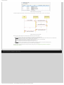
Modelling
To build an ASD component using the ASD:Suite, follow these steps:
1. Create an interface model that specifies the service that is going to be implemented by the component. See "Creating an
interface models" for details.
2. Identify the used services, i.e. services that provide functionality that is going to be used in the design of the component.
3. For each used service, identify one or more components that implement that service.
4. Create the design model for the considered component:
❍
Specify the service that is going to be implemented.
❍
Specify the services that are going to be used.
❍
Designate components for the used services.
❍
Build the SBS for the design model.
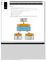
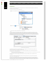
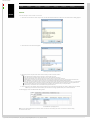
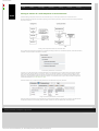
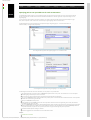
The construction of an Alarm System is used to illustrate the above mentioned steps. The following figure presents the main
component of such a system (the box named "AlarmSystem"), together with the service to implement, AlarmSystem, and the
services to be used: Sensor and Siren:
© 2012 Verum Software Technologies B.V. All rights reserved
Terms of use | Privacy Policy
http://community.verum.com/documentation/user_manual_pdf.aspx/8.5.0/modelling/workflow [03/12/2012 09:32:17]
ASD:Suite User Manual
●
Home
●
Product
●
Technology
●
Resources
●
Training
●
Purchase
●
Company
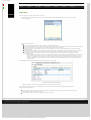
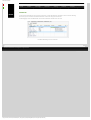
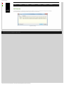
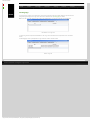
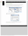
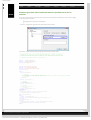
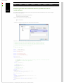
Creating an Interface Model
These are the steps to create a new interface model:
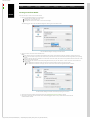
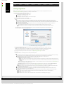
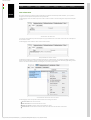
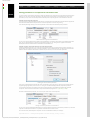
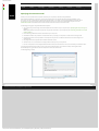
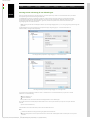
1. Open the "New Model" dialog. This can be done by:
❍ Selecting the "File->New" menu item, or by
❍ Clicking "New" in the Toolbar, or by
❍ Selecting the "Create a new model..." item on the Start Page.
The following figure shows the "New Model" dialog after selecting one of the above choices:
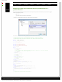
The "New Model" dialog for creating an interface model
2. Specify a name for the service under "Model name:"
Note:
❍ If the field was empty, the specified name designates the file name of the interface model (see next figure) and the name of the
service. You should not use spaces in this name and no special characters which would make the file unrecognisable by the operating
system.
❍ If there is already a file name specified in the "File location and name:" field, the file name is not updated when the information in the
"Model name:" field is changed.
❍ You can specify a file name in the file lookup dialog obtained when you press the "Browse..." button next to the "File location and
name:" field
■ If the "Model name:" field was empty, the name of the service will be the same as the name of the file.
■ If the "Model name:" field was not empty, the name of the service will not be changed after the file is selected.
The "New Model" dialog for interface models after specifying a service name
3. Specify the execution model for this interface model. See "Specifying the execution model" for details.
4. Click "OK" to create and save the interface model. The following figure shows a newly created interface model with all
dockable windows loaded.
http://community.verum.com/documentation/user_m....5.0/modelling/create_im/create_interface_model (1 of 2) [03/12/2012 09:32:20]
ASD:Suite User Manual
A newly created interface model
Note: To change the name of the service, select the service name in the "Model Explorer", press F2 or double click, and type in a
new name. This does not change the name of the file.
The following tabs are shown in the "IAlarm (IAlarm.im)", which is the "Model Editor" for the IAlarm.im:
●
IAlarm: a tab for the main machine, containing the following sub-tabs:
❍
SBS: shows the SBS for the machine;
❍
States: shows the list of states defined in the machine and facilitates the specification of informal design information about the states;
❍
State Variables: shows the list of state variables defined for the machine and facilitates the declaration and specification of
state variables.
Note: In an interface model there is only one machine.
●
Application Interfaces: shows the set of call events and reply events for each defined application interface and facilitates
the specification of new application events.
●
Note: There is one sub-tab per defined interface.
Notification Interfaces: shows the set of events for each defined notification interface and facilitates the specification of
new notification events.
●
Note: There is one sub-tab per defined interface.
Modelling Interfaces: shows the set of events for each defined modelling interface and facilitates the specification of new
notification events.
●
Note: There is one sub-tab per defined interface.
Tags: shows the list of requirements defined for the component and facilitates the specification of additional requirements
that emerge during the design phase.
© 2012 Verum Software Technologies B.V. All rights reserved
Terms of use | Privacy Policy
http://community.verum.com/documentation/user_m....5.0/modelling/create_im/create_interface_model (2 of 2) [03/12/2012 09:32:20]
ASD:Suite User Manual
●
Home
●
Product
●
Technology
●
Resources
●
Training
●
Purchase
●
Company
Interfaces and Events
The first thing to do when creating an interface model, is to define its interfaces and events. An event is analogous to a method or
callback that your component exposes. An interface groups multiple events together.
Application Interfaces and Application Events
All interface models must have at least one application interface.
●
●
●
Go to the "Application Interfaces" tab and click the blue plus sign to create a new interface.
In the dialog that appears, type a name and click OK. The name must begin with an underscore or letter and continue with
letters, underscores or numbers
Click OK. A new tab appears for the application interface.
Application interfaces have two types of events: Call Events and Reply Events. You see a table for each.
Call Events
The declaration of a call event consists of:
●
A name: this identifies the event
●
Parameters (optional): used for passing arbitrary data through ASD components, see Parameters.
●
A return type: valued or void
An example of a call event is DoSomething([in]p1:string, [out]p2:int):void. Here, "DoSomething" is the event
name, p1 and p2 are parameters, and "void" is the return type.
Parameters are described in detail in Parameters.
The return type determines what the possible reply events are for the call event. A call event with a "void" return type always has
the standard "VoidReply" reply event. A call event with a "valued" return type can use all user-defined reply events.
Reply Events
Reply events are the possible return values to the call events. Usually they are translated to enumeration types in the generated
code. When you create an application interface, you get one reply event for free: "VoidReply". This is a special event that is used in
the SBS as a reply to void call events. Next to this event, you can create your own reply events for any valued call events (e.g. Yes,
No, Ok, Fail etc).
Note:
If you have no void call events, but only valued ones, you can optionally delete the "VoidReply" event.
Reply events are declared merely by typing a unique name.
Notification Interfaces and Notification Events
Notification events are analogous to callbacks in a programming language. In ASD, you define a notification interface as follows:
●
●
●
Go to the "Notification Interfaces" tab and click the blue plus sign to create a new interface.
In the dialog that appears, type a name and click OK. The name must begin with an underscore or letter and continue with
letters, underscores or numbers
Click OK. A new tab appears for the notification interface.
At the top of the notification interface tab there is a checkbox marked "Broadcast". If this is checked, the notification interface can
be used by multiple clients and the clients can subscribe and unsubscribe to its events at run-time. This is described in more detail in
Broadcasting Notifications.
Notification Events
The declaration of a notification event consists of:
●
A name: this identifies the event
●
Parameters (optional): used for passing arbitrary data through ASD components, see Parameters.
An example of a notification event is ProcessingDone([in]result:string). Here, "ProcessingDone" is the event name,
and "result" is a parameter.
Parameters are described in detail in Parameters. Notification events can only have [in] parameters.
The Notification Events table has a column called "Yoking treshold". This column is only useful if the interface model is a specification
of a foreign component. You use it to say that the notifications will arrive at a slow enough rate to be processed by clients without
their queue becoming full. It is a promise to the outside world. The yoking treshold is an integer number that indicates the maximum
number of events that will end up in the client's queue at any given time. This is described in more detail in Yoking Notification
Events.
Note:
Yoking makes a promise to the user of the interface model, which ASD cannot verify. Therefore, if the foreign component does not
adhere to the promise, ASD model verification will not catch this. Often, it is possible to use safer constructs such as singleton
notification events or to define a protocol that limits the notifications.
Modelling Interfaces and Modelling Events
If the interface model has so-called spontaneous behaviour (e.g. it sends a notification event without being told to do so by the
outside world), you need a modelling event to be able to specify this in the SBS. After all, every line in the SBS needs a trigger but
there is no outside event to be the trigger. Modelling events are not real events, but only used for modelling.
●
●
●
Go to the "Modelling Interfaces" tab and click the blue plus sign to create a new interface.
In the dialog that appears, type a name and click OK. The name must begin with an underscore or letter and continue with
letters, underscores or numbers
Click OK. A new tab appears for the modelling interface.
http://community.verum.com/documentation/user_m...spx/8.5.0/modelling/create_im/interfaces_events (1 of 2) [03/12/2012 09:32:24]
ASD:Suite User Manual
Modelling Events
Modelling events are declared just by typing a name in the Event column.
Next to the Event column, there is a column called "Abstraction Type". Each modelling event is either Inevitable or it is Optional. The
only difference between the two is how the event is handled by the model verification. For inevitable modelling events, the
verification only checks the cases where the event does occur, i.e. it assumes that the event will eventually occur if we wait long
enough. For optional modelling events, the model verification also checks the cases where the event never happens (which could be
a cause of deadlock).
© 2012 Verum Software Technologies B.V. All rights reserved
Terms of use | Privacy Policy
http://community.verum.com/documentation/user_m...spx/8.5.0/modelling/create_im/interfaces_events (2 of 2) [03/12/2012 09:32:24]
ASD:Suite User Manual
●
Home
●
Product
●
Technology
●
Resources
●
Training
●
Purchase
●
Company
Yoking Notification Events
The ASD:Suite enables you to specify the maximum number of occurrences at any given time in the queue of notification events. In
ASD this number is called the Yoking Threshold. This number can be determined after a thorough analysis of the timing-behaviour
of the system and after determining the arrival- and service intervals of the queue.
Many real world designs must accept notification events generated by the environment and which can not be controlled by the
design. The real executing system works without problems because the arrival intervals of the events are much longer than the
service times and thus, they do not flood the queue or starve other system activity. Also, in reality, the queue is always "long enough"
that it never becomes blocking.
In verification using the ASD:Suite there is no direct way of representing this temporal behaviour and the queue must be kept
small enough in size to avoid state explosion and endless verification. The remedy for this is based on the "yoking" concept. The idea is
to approximate the effect of temporal behaviour by limiting the number of such events that can be in the queue at any given time. Such
a limit is called an event threshold and is specified as "Yoking Threshold" for each notification event to be limited / restricted.
Conceptually, by specifying an event threshold for a notification event you state that under expected runtime conditions, the
arrival rate and service time of the event are such that the number of unprocessed notification events of the specified type will never
exceed the specified limit.
Notification events originate from interface models of used services and are either an action to an application interface trigger or an
action to a modelling event. ASD semantics require that executing a notification as an action is never blocking so the notification
can not be prevented, instead the trigger that results in the notification is prevented. The solution is to limit notifications that
are actions to modelling events by enabling and disabling the modelling events. Notification events arising as actions to
application interface triggers can not be limited because the trigger can not be disabled.
WARNING: Yoking should be used wisely; when the assumptions about arrival intervals and service intervals are not correct
the verification results may give a false impression. If the arrival rate during execution is higher than assumed with Yoking, the
queue may still fill up. For C-code this may lead to a runtime assertion failure, since the Queue size in C is fixed, and will assert when
it overflows. For the other languages the queue size is only bound by memory/stack size, the problem is not as critical, but eventually
the queue can still overflow.
The ModelBuilder enables the indication in the interface model for each notification event whether the respective event should
be restricted by means of yoking. For each notification event you can indicate the event threshold by typing a value in the "Yoking
Threshold" column:
Client notification with yoking threshold
Note:
● A threshold should be smaller than or equal to the queue-size in the using design model (otherwise a queue size violation
modelling error can still occur).
●
●
●
If the threshold is set to zero or remains empty, this implies there is no threshold, and the notification event is not restricted.
The Yoking Threshold is to be specified in the interface model because in effect it is a statement about the frequency with which
the implementation of the interface model will generate events.
The Yoking Threshold has to be specified per notification event and NOT per triggering modelling event. This is because of the
same reasons as for the previous point; it is a statement of the frequency with which an event will be generated.
A modelling event will be yoked (i.e. the corresponding rule case will be disabled) if the number of any of the restricted
notification events in the sequence of actions already in the queue is larger than or equal to the defined event threshold
(irrespective of the total number of events in the queue). In this case, the complete rule case is disabled, and thus no response
is triggered, no state variable update is performed and the specified state transition will not occur.
Note: A rule case with a non-modelling event as trigger will never be disabled, i.e. there will be no check to see if the number of any
of the restricted notification events in the sequence of actions already in the queue is larger than or equal to the defined event
threshold.
A modelling event will NOT be yoked (i.e. the corresponding rule cases will NOT be disabled) when the number of all of those restricted
notification events already in the queue is less than the defined event threshold for each restricted notification event respectively.
The following figure shows an SBS in which the modelling event is marked as <yoked> since in the Actions column a yoked
notification event is specified, in this case the DetectedMovement notification:
Yoked modelling event
http://community.verum.com/documentation/user_manual_pdf.aspx/8.5.0/modelling/create_im/yoking (1 of 2) [03/12/2012 09:32:27]
ASD:Suite User Manual
© 2012 Verum Software Technologies B.V. All rights reserved
Terms of use | Privacy Policy
http://community.verum.com/documentation/user_manual_pdf.aspx/8.5.0/modelling/create_im/yoking (2 of 2) [03/12/2012 09:32:27]
ASD:Suite User Manual
●
Home
●
Product
●
Technology
●
Resources
●
Training
●
Purchase
●
Company
Creating a Design Model
Note: In order to create a design model, you must already have created the interface model for the implemented service. See
"Creating an interface model" for guidelines on creating an interface model.
These are the steps to create a new design model:
1. Open the "New Model" dialog. This can be done by:.
❍ Selecting the "File->New" menu item, or by
❍ Clicking "New" in the Toolbar, or by
❍ Selecting the "Create a new model..." item on the Start Page.
2. Select the design model icon in the left pane.
3. Specify a name for the service under "Model name:"
Note:
❍ If the field was empty, the specified name designates the file name of the design model and the name of the component. You
should not use spaces in this name and no special characters which would make the file unrecognisable by the operating system.
❍ If there is already a file name specified in the "File location and name:" field, the file name is not updated when the information in the
"Model name:" field is changed.
❍ You can specify a component name by specifying a file name in the file lookup dialog obtained when you press the "Browse..."
button next to the "File name:" field
■ If the "Model name:" field was empty, the name of the component will be the same as the name of the file.
■ If the "Model name:" field was not empty, the name of the component will not be changed after the file is selected.
The following figure shows the "New Model" dialog after you have selected the design model icon in the left pane and you
specified "Alarm" as name for your design model:
The "New Model" dialog for creating design models
4. Specify the implemented service by filling in the path or by selecting the file using the "Browse..." button next to the
"Implement interface model:" field.
Note: You are able to specify if you would like to create the SBS of the design model based on the SBS of the specified
implemented interface model. This can be done by checking the "Copy SBS from interface model" checkbox.
5. Specify the component type for the ASD component. See "Specifying component type" for details.
6. Click "OK".
When you click OK, a new design model is created, saved and opened.
Note:
❍
❍
To change the name of the component, double click on the component name and type a new name. You may also do this by selecting
the component name in the "Model Explorer" window and pressing F2. This does not change the name of the file
The following tabs are shown in the "Alarm (Alarm.dm)", which is the "Model Editor" for the Alarm.dm:
■ Alarm: a tab for the main machine, containing the following sub-tabs:
■ SBS: shows the SBS for the machine;
■ States: shows the list of states defined in the machine and facilitates the specification of informal design information about the
states;
■ State Variables: shows the list of state variables defined for the machine and facilitates the declaration and specification of state
variables.
Note: In a design model, there might be more machines: one main machine and zero or more sub machines. See "Sub Machines" for
details about adding and using sub machines.
Used Services: shows the list of used services together with the interfaces that are used in three sub-tabs: Primary References,
Secondary References and a tab per used service. See "Specifying used services" for details about used services.
■ Tags: shows the list of requirements defined for the component and facilitates the specification of additional requirements that
emerge during the design phase.
In the remainder of this user guide, we use "Alarm" as the name of the component and the main machine.
The ASD:Suite ensures that the set of all triggers in each state of each machine of the design model is consistent with the set of
events of the implemented service and used services.
The following is copied from the interface model into the design model if you have checked the "Copy SBS from interface model"
check box:
■ The states of the main machine with all information stored in the interface model (user columns and descriptions).
■ The state variables of the main machine.
■ The tags.
■ The SBS of the main machine, with the exception of the rule cases that have a modelling event as trigger.
■
❍
❍
❍
© 2012 Verum Software Technologies B.V. All rights reserved
http://community.verum.com/documentation/user_.../8.5.0/modelling/create_dm/create_design_model (1 of 2) [03/12/2012 09:32:31]
ASD:Suite User Manual
Terms of use | Privacy Policy
http://community.verum.com/documentation/user_.../8.5.0/modelling/create_dm/create_design_model (2 of 2) [03/12/2012 09:32:31]
ASD:Suite User Manual
●
Home
●
Product
●
Technology
●
Resources
●
Training
●
Purchase
●
Company
Primary References
A primary reference is defined by the following:
●
Reference Name[#instances]: the name of the reference with the number of instances in the used service reference. The size of
the primary reference is:
❍
❍
Fixed, if at design-time the number of instances is known. For example, WindowSensors[2]
Configurable, if at design-time the number of instances is not known. The size of the primary reference is configurable if you:
■
■
Specify * as #instances. In this case the size is returned by a 'configurator' during the construction of the service instances.
Specify construction parameters. In this case the size of the reference is determined by the size of the construction parameter(s). See
"Defining construction parameters" for details.
●
Service: the service (specified by an interface model) that the instances of the reference instances implement
●
Used Interfaces: a subset of the interfaces of the used service.
●
Construction: used in the generated code during construction of the used service reference. This is what you can specify in this cell:
A component name - If the used service is an ASD component, this is the name of the design model, if the used component is a
foreign component, the actual component name of that foreign component must be used.
❍ A component name followed by a list of arguments for the GetInstance call to the component. The arguments can be literals
(between $s), construction parameters or even already defined primary references.
❍ A use statement in the form of "use arg" to inject a component using either a primary reference or a construction parameter.
See "Construction Parameters" for details about the concepts of Construction Parameters, and see "Defining construction
parameters" for details about defining construction parameters for your ASD component.
❍
●
#Instances in Verification: The number of instances for the reference that will be used in verification. If this field is left empty,
the number indicated in the first column is used. If the first column does not contain an explicit number of instances (i.e. [*] is
used), this field must be filled in.
Warning / disclaimer: if the number of elements in a reference used for verification differs from the number of elements indicated
in the design, it is up the user to prove that the verification results hold for more elements in the reference. The ASD:Suite can
only guarantee what has been explicitly verified.
●
Comments: descriptive text.
Note: A primary reference can not be empty and is immutable (the contents are defined during construction and are not changed
at runtime)
Take the following steps to create and specify a primary reference:
●
Select the "Used Services" node in the "Model Explorer" window and open the context menu by pressing the right button of the
mouse. In the context menu, select "New Primary Reference".
The following figure shows the context menu of the "Used Services" node:
The "New Primary Reference" context menu item under "Used Services"
●
Fill in the data in the "New Primary Reference" dialog window. The following figure shows an empty "New Primary Reference"
dialog window:
http://community.verum.com/documentation/user_.../modelling/create_dm/specify_primary_reference (1 of 3) [03/12/2012 09:32:35]
ASD:Suite User Manual
The "New Primary Reference" dialog window
Note: The currently loaded interface models, with the exception of the one for the implemented service, are shown in the list of
loaded services. If you want to select a service which is not already loaded, you have to set the "Select Service from the file
system" radio-button and select the interface model of the respective service after pressing the Browse button. In this case when
the primary reference is created the service dependencies are also created / updated.
●
Repeat the previous steps for all required service instances.
The following figure shows the Primary References defined for the Alarm system:
A design model with used services
The following figure shows the "Used Services" tab after creating the primary references:
The "Used Services" tab with the specified used services
Note: When you want to change any data for the created primary references, like the number of instances, edit the respective cell
in the "Primary References" tab.
Specify different components with the same service
The following figure shows the situation where two primary references for service "ISensor" are specified, one named DoorSensor
and the other named WindowSensor. The components are differentiated by naming them DoorAlarmSensor and
WindowAlarmSensor respectively.
http://community.verum.com/documentation/user_.../modelling/create_dm/specify_primary_reference (2 of 3) [03/12/2012 09:32:35]
ASD:Suite User Manual
Different components with the same service
© 2012 Verum Software Technologies B.V. All rights reserved
Terms of use | Privacy Policy
http://community.verum.com/documentation/user_.../modelling/create_dm/specify_primary_reference (3 of 3) [03/12/2012 09:32:35]
ASD:Suite User Manual
●
Home
●
Product
●
Technology
●
Resources
●
Training
●
Purchase
●
Company
Sub Machines
The ASD:Suite supports hierarchical machines for design models. This is restricted to one level of sub machines. In other words, a
sub machine can not have a Super state.
You can add a sub machine in one of the following ways:
●
Right-click on the Sub Machines node in the "Model Explorer":
Menu item to create a sub machine
●
Click-on/Push the
button in the Model Editor:
The button to add a sub machine
●
Press the "Ctrl+T" hotkey in the Model Editor of a design model
The new sub machine will be created after you specify a name. Additionally, the corresponding transfer interface is created;
this interface is used for the synchronisation between the main machine and the sub machine. This transfer interface inherits its
name from the name of the sub machine. For each transfer interface one or more call events must be declared, as well as one or
more reply events. The declarations works in the same way as defining call events and reply events for an application interface with
the observation that transfer call events are always of valued type and can carry zero or more in, out and/or inout parameters and
that transfer reply events can carry zero of more in parameters.
Transfer call events and reply events
The specified transfer call events are automatically added to the set of triggers of the created sub machine, and the transfer
reply events are added to the set of triggers of the main machine.
In the main machine all newly created transfer reply events will get a default "Blocked" action, since the transfer reply event is
only expected in the corresponding Super state.
Note: The border of the cell in which you specify an event is coloured red if the declaration is not syntactically correct. The event is
not stored in the model until the declaration is correct.
In the newly created sub machine all triggers except the transfer call events get a "Blocked" action in the initial state of the
sub machine.
Then the new sub machine must be correlated to a Super state in the main machine. First, a new state must be created that
will become the corresponding Super state.
Then, on the rule case that will define the transition to the newly created state, add a transfer call event corresponding to the
sub machine as the last action in the sequence of actions, and select the newly created state in the "Target State" column. Now,
the new state has become a Super state. The "Blocked" action is filled in for all triggers in the new Super state with the exception of
the transfer reply events. Then fill in the proper action and target state for the transfer reply event(s) that correspond with the
http://community.verum.com/documentation/user_...df.aspx/8.5.0/modelling/create_dm/sub_machines (1 of 2) [03/12/2012 09:32:38]
ASD:Suite User Manual
sub machine. The Super state is now ready.
Then, the sub machine remains to be completed. This is done in the normal way of defining the SBS, with one addition: after a
transfer reply event is used as an action in a sub machine, the target state always must be the initial state of the sub machine.
The transfer reply event returns control to the main machine, and renders the sub machine inactive. When the main machine
after some time re-activates the sub machine, this will again have to start from the initial state.
© 2012 Verum Software Technologies B.V. All rights reserved
Terms of use | Privacy Policy
http://community.verum.com/documentation/user_...df.aspx/8.5.0/modelling/create_dm/sub_machines (2 of 2) [03/12/2012 09:32:38]
ASD:Suite User Manual
●
Home
●
Product
●
Technology
●
Resources
●
Training
●
Purchase
●
Company
State Variables for Used Service References
Used service reference state variables are used service references whose contents can change dynamically. They can be used in
guards, actions and state variable updates. For example to keep track of the used service references when iterating over them.
See "Specifying used services" for details about used service references, and see "Specifying state variables" for details about
state variables.
Operators for used service reference state variables
Used service reference state variables have a specific set of operators. The following table introduces the operators that can be
used with used service reference state variables. In addition it provides a short description and definition of each operator. In this
list, S, S1 and S2 are references and n and m are integers.
Operator
#S
<>
S1 == S2
Description
cardinality: number of elements in S (duplicates included)
empty reference
equality operator
S1 != S2
inequality operator
S1 = S2
S1+S2
assignment
concatenation: pasting S2 behind S1
head(S1)
head: reference containing the first element of reference S1 if present and
otherwise <>
tail(S1)
tail: reference containing all but the first element of S1 (if present)
S1[n]
indexing: reference containing the nth element of S1 if present and otherwise <>
S1 in S2
subset: each element in S1 is present in S2
that
Definition
≡
#<> == 0
S1 == S2
#S1 == #S2
∧ ∀(n : 1 ≤ n ≤ #S1 : S1[n] == S2[n])
S1 != S2
≡
not(S1 == S2)
establishes S1 == S2
S == S1+S2
≡
#S == #S1 + #S2
∧ ∀(n : 1 ≤ n ≤ #S1 : S[n] == S1[n])
∧ ∀(n : 1 ≤ n ≤ #S2 : S[n+#S1] == S2[n])
S == head(S1)
≡
#S1 < 1 => S == <>
∧ #S1 ≥ 1 => S == S1[1]
S == tail(S1)
≡
#S1 < 1 => S == <>
∧ #S1 ≥ 1 => #S == #S1-1
∧ #S1 ≥ 1 => ∀(n : 1 ≤ n ≤ #S1-1 : S[n] == S1[n+1])
S == S1[n]
≡
n < 1 ∨ n > #S1 => S == <>
∧ 1 ≤ n ≤ #S1
=> S == S1[n]
S1 in S2
≡
∀(n : 1 ≤ n ≤ #S1 : ∃(m : 1 ≤ m ≤ #S2 : S1[n] == S2
[m]))
that: a reference of one element representing the component instance that
generated the trigger of the rule case
The "in" operator deserves some additional explanation. It implements the subset operation and not the subsequence operation.
This means that order and multiplicity are not considered in the comparison. The expression "(S1 in S2) and (S2 in S1)" means that
S1 and S2 are set-equal. For example, for two arbitrary references S1 and S2, the expression "S1+S1+S2" is set-equal to "S2+S1", but
"S1+S1+S2 == S2+S1" only holds if S1 equals <>.
Examples
Examples of how to use the operators in the "Guard", "State Variable Updates", and/or "Actions" columns:
Operator Description
Guard example Actions example
State Variable Updates example
#
cardinality
i==#S
i=#S
<>
empty reference
S==<>
S=<>
==
equality operator
S1==S2
b=(S1==S2)
!=
inequality operator S1!=S2
b=(S1!=S2)
=
assignment
S=S1
+
concatenation
S==S1+S2
S=S1+S2
head
head
S==head(S1)
head(robots):IRobot.Start() S=head(S1)
tail
tail
S==tail(S1)
tail(robots):IRobot.Start()
S=tail(S1)
[]
indexing
S==S1[2]
robots[2]:IRobot:Start()
S=S1[2]
in
subset
S1 in S2
b=S1 in S2
that
that
S[3]==that
that:IRobot.Start()
S=that
Note: S, S1 and S2 are all used service reference state variables; variable i is an integer state variable; variable b is a boolean
state variable.
Here are a few examples of how to use used service reference state variables and their operators in the SBS of a design model:
1. Iterate over a number of sensors to activate them one by one:
Iterate over a used service reference state variable member by member
Note:
❍
❍
"activate" is a used service reference state variable for all the to-be-activated sensors defined for the model. Its initial value is all the
sensors, i.e. all door and window sensors: DoorSensor+WindowSensor
"deactivate" is a used service reference state variable for all the sensors to be deactivated. Its initial value is the empty sequence "<>".
2. Deactivate all sensors and wait for the result of deactivation for each sensor respectively:
http://community.verum.com/documentation/user_...f.aspx/8.5.0/modelling/create_dm/usr_behaviour (1 of 2) [03/12/2012 09:32:42]
ASD:Suite User Manual
Perform an action on all members of a used service reference variable and wait for all of them to respond
Note:
❍
❍
❍
"deactivate" is a used service reference state variable for all the sensors to be deactivated.
"deactivated" is a used service reference state variable for all the sensors which are deactivated.
The "deactivate in deactivated + that" guard evaluates to true if all members of "deactivate" are present in "deactivated +
that". "deactivated + that" translates to the "deactivated" sequence together with the current service instance
You can refer to used service references (primary/secondary references or used service reference state variables in combination
their operators) in several ways when adding actions:
Syntax
Description
myReference:IMyAPI.Start()
call Start on every service instance in myReference
myReference[3]:IMyAPI.Start()
call Start on the third service instance in myReference
that:IMyAPI.Start()
call Start on the service instance that generated the trigger
head(myReference): IMyAPI.Start() call Start on first service instance in myReference
tail(myReference): IMyAPI.Start()
call Start on every service instance in myReference, except the first one
where myReference denotes a primary reference, a secondary reference or a used service reference state variable.
Note:
●
The used service reference of a valued action must always be a singleton, i.e. a reference of length 1.
●
The used service reference of a void action must contain at least one element.
© 2012 Verum Software Technologies B.V. All rights reserved
Terms of use | Privacy Policy
http://community.verum.com/documentation/user_...f.aspx/8.5.0/modelling/create_dm/usr_behaviour (2 of 2) [03/12/2012 09:32:42]
ASD:Suite User Manual
●
Home
●
Product
●
Technology
●
Resources
●
Training
●
Purchase
●
Company
Singleton Notification Events
The ASD:Suite enables you to specify that at any given moment in time a specific notification event from a used service instance
should occur only once in the queue of your component. This is done by flagging the respective event as a Singleton.
Note:
● Flagging an event as singleton does not mean that the respective event can not occur anymore until taken out of the queue. It
only means that when the respective event occurs and there is already one in the queue, the latest occurrence will be
considered irrelevant and will be discarded.
●
Good candidates for singleton events are, for example, notifications from a driver reporting new data or progress notifications.
In case you want to flag an event on a used service notification interface as Singleton you should open a design model in which the
respective notification interface is declared as used notification interface and you should view its events in the "Used Notification
Interfaces" tab.
The following figure shows how to flag the ISensor_CB.Deactivated event as a Singleton:
Flag an event as Singleton
ASD guarantees that per instance of a used service notification interface there is at most one event in the queue for the events
flagged as Singleton. For example, if a notification event "A"of interface "IPublisher"is flagged as "Singleton", then:
1. If one instance of IPublisher is used, at most one "A" is in the queue at any given time;
2. If there are N instances of IPublisher, at most N "A"s are in the queue at any given time; This is independent of whether the
underlying Publisher component is a Singleton Component or Multiple Component.
© 2012 Verum Software Technologies B.V. All rights reserved
Terms of use | Privacy Policy
http://community.verum.com/documentation/user_manual_pdf.aspx/8.5.0/modelling/create_dm/singleton [03/12/2012 09:32:45]
ASD:Suite User Manual
●
Home
●
Product
●
Technology
●
Resources
●
Training
●
Purchase
●
Company
Behaviour in an ASD model
In order to specify behaviour in an ASD model you have to fill-in each line in the SBS tab, also known as rule cases, with guards,
actions, state variable updates, target state, comments, and tags. By this you will define behaviour for each event which can trigger
an action, or more actions, in various states of your system. These events are called triggers.
Note:
●
In order to specify guards and state variable updates you need to define state variables.
●
For each state you are defining you can specify additional (design) information.
The ModelBuilder ensures that the following events are present in each state specified in the SBS tab of the main machine of an
interface model as triggers:
●
All application call events, and
●
All modelling events
The ModelBuilder ensures that the following events are present in each state specified in the SBS tab of the main machine of the
design model as triggers:
●
All implemented service application call events.
●
All used service notification events for all the used service notification interfaces that are observed.
●
All used service application reply events for all the used services application interfaces specified as used interfaces.
●
All transfer reply events for all transfer interfaces defined in the design model.
The ModelBuilder ensures that the following events are present in each state specified in the SBS tab of a sub machine of the
design model as triggers:
●
All implemented service application call events.
●
All used service notification events for all the used service notification interfaces that are observed.
●
All used service application reply events for all the used services application interfaces specified as used interfaces.
●
All transfer call events for the transfer interface of the sub machine
Note:
●
See "Specifying used services" for details about used services.
●
See "Sub machines" for details about using sub machines.
© 2012 Verum Software Technologies B.V. All rights reserved
Terms of use | Privacy Policy
http://community.verum.com/documentation/user_manual_pdf.aspx/8.5.0/modelling/behaviour/behaviour_intro [03/12/2012 09:32:48]
ASD:Suite User Manual
●
Home
●
Product
●
Technology
●
Resources
●
Training
●
Purchase
●
Company
State Variables
State variables provide means to capture fine-grained history as opposed to states which capture the more coarse-grained
history. Guards are used to base control-flow decisions on state variables and state variable updates are used to change the values
of state variables.
Note: Because ASD has strict separation of control and data, state variables can not be used as arguments of events and
event arguments can not be used in a guard or in a state variable update expression.
The "State Variables" tab enables the specification of state variables, their initial values, and comments. The following figure shows
an empty state variable declaration for the "IAlarm" main machine:
The ASD:Suite - the "State Variables" tab
In order to specify state variables, you must specify a name for the respective variable, the type of the variable, type constraints and
an initial value. To do this, enter the name of the variable in the "State Variable" column and the initial value in the "Initial
Value" column.
The following figure shows a filled-in "State Variables" tab for the "IAlarm" main machine:
State variable specification for the "IAlarm" machine
You can specify one of the following types in the Type column:
●
●
●
●
Integer: for integer state variables. Use of integer state variables must always be within a defined range. Unbounded integer
state variables would cause problems during verification.
Note: To specify the range of values for a variable, you have to fill in the "Constraint" column following the suggested format.
Boolean: for boolean state variables. Boolean state variables have either "true" or "false" as value.
Enumeration: for enumeration state variables. The value of an enumeration state variable can be any text which conforms to
the naming conventions used in ASD modelling, but can not be the same as the name of a state variable defined for the same
machine. The set of values for an enumeration state variable is built up by parsing through the ASD model and collecting data from
the assignments to the respective enumeration state variable specified in the "State Variable Updates" column of the SBS tab for
the machine in which the enumeration state variable is defined.
Used Service Reference: for used service reference state variables. Used service reference state variables are mutable sequences
of component instances.
Note: Used service reference state variables can be specified only in design models.
The following list states the characteristics of the used service reference state variables:
❍ The name and maximum size of the used service reference state variable is recorded in the "State Variable" column of the
"State Variables" tab. The maximum size must be specified within rectangular brackets directly after the variable name (e.g. Robots[5]).
❍ For a used service reference state variable the data in the "Constraint" column specifies the type of the variable by referring to the
type of a primary reference.
Note: You can not specify a secondary reference as the type of a used service reference state variable in the "Constraint" column.
Instead, you have to specify one of the primary references used to construct the respective secondary reference.
❍ The initial value of a used service reference state variable is a string that can be constructed from the names of primary and/
or secondary references and the operators described in "State Variables for Used Service References".
Warning: The usage of many or large used service reference state variables will increase the state-space considerably and may result
in verification performance problems.
See "Specifying guards" for details about the usage of state variables in guards, and see "State Variable Updates" for details about
using state variables in state variable updates.
© 2012 Verum Software Technologies B.V. All rights reserved
Terms of use | Privacy Policy
http://community.verum.com/documentation/user_manual_pdf.aspx/8.5.0/modelling/behaviour/state_variables [03/12/2012 09:32:52]
ASD:Suite User Manual
●
Home
●
Product
●
Technology
●
Resources
●
Training
●
Purchase
●
Company
State Information
Since at the creation of the interface model an initial state was created and automatically named "NewState", you may want to
change this name and provide a description for the respective state.
The following figure shows the "States" tab, which is used to create new states or rename existing states and provide a description
for them:
The ASD:Suite - the "States" tab
To rename an existing state and provide a description for it, type a different name in the "State" column and enter a description in
the "Comments" column.
The following figure shows a filled-in "States" tab for machine "IAlarm":
State specification for machine "IAlarm"
The ASD:Suite provides the possibility to add design information to a state description. This is achieved via adding so called user
columns next to the description. You have to select the "New User Column" context menu item obtained by right-clicking with the
mouse on one cell of the state declaration (see next figure ) or you have to press "Ctrl+U".
The context menu item to add a new user column
The following figure shows the operations that are allowed on an existing user column:
●
New User Column: add a new user column
●
Delete User Column: remove the selected user column
●
Rename User Column: change the name of the selected user column
●
Autosize columns: set the size of the columns to fit the size of the text in the cells and the column titles
http://community.verum.com/documentation/user_m...l_pdf.aspx/8.5.0/modelling/behaviour/state_info (1 of 2) [03/12/2012 09:32:55]
ASD:Suite User Manual
Operations with a user column in the States tab
© 2012 Verum Software Technologies B.V. All rights reserved
Terms of use | Privacy Policy
http://community.verum.com/documentation/user_m...l_pdf.aspx/8.5.0/modelling/behaviour/state_info (2 of 2) [03/12/2012 09:32:55]
ASD:Suite User Manual
●
Home
●
Product
●
Technology
●
Resources
●
Training
●
Purchase
●
Company
Actions
These are the steps to insert an action in a rule case:
1. Select the cell in the Actions column and press F2 or double-click with the left button of the mouse. The "Select Actions" dialog appears:
The ASD:Suite-the "Select Actions" dialog
2. Select the action from the list that appears:
Selecting an event to be added as action
3. Repeat the previous step with other actions from the list if you wish to add more actions
Note:
❍ The "Select Actions" dialog is split in two panes: one text editor and a list.
❍ Press the Tab key or Select the panes with the mouse to switch between the panes.
❍ The text editor enables you to type the name of the actions and/or to set the order of actions.
❍ While typing, the actions in the list are filtered out using sub-string matching easing up your job to specify the desired action.
❍ Press Shift+Enter or Alt+Enter in the text editor to insert a blank line between two already specified actions.
❍ Pressing Tab in the text editor while you specify an action performs prefix completion for the respective action, i.e. it extends the
currently specified name to the longest common prefix within the existing actions which matches the currently specified text.
❍ Cut-Copy-Paste-Delete operations are enabled in the text editor part in the same way as in any text editor.
❍ Use Ctrl+Up or Ctrl+Down to move a selected action up/down in the list
4. When all the actions are specified, switch to the text editor of the "Select Actions" dialog and press Enter to add the actions in the SBS.
Note: If you pressed Enter in the text editor part and there are wrongly specified actions, those will be underlined.
The following figure shows the SBS tab after adding actions.
The SBS tab after specifying actions
Note: You can select multiple cells in the Actions column to insert the same action(s) into them. The cells do not have to belong
to consecutive rule cases.
http://community.verum.com/documentation/user_manual_pdf.aspx/8.5.0/modelling/behaviour/actions (1 of 2) [03/12/2012 09:32:59]
ASD:Suite User Manual
© 2012 Verum Software Technologies B.V. All rights reserved
Terms of use | Privacy Policy
http://community.verum.com/documentation/user_manual_pdf.aspx/8.5.0/modelling/behaviour/actions (2 of 2) [03/12/2012 09:32:59]
ASD:Suite User Manual
●
Home
●
Product
●
Technology
●
Resources
●
Training
●
Purchase
●
Company
Target State
These are the steps to specify a target state in a rule case:
1. Select the cell in the "Target State" column and press F2 or double-click with the left button of the mouse. The "Select Target
State" dialog appears:
The ASD:Suite-the "Select Target State" dialog
2. Select the state from the list
Note:
❍ The "Select Target State" dialog is split in two panes: one text editor and a list.
❍ You can switch between the panes of the "Select Target State" dialog by pressing the Tab key or by selecting the panes with the mouse.
❍ The text editor enables you to type the name of the desired state or to create a new state.
❍ While you specify the state manually the states in the list are filtered out using sub-string matching easing up your job to specify
the desired state.
❍ Pressing Tab in the text editor while you type a state name performs prefix completion for the respective state name, i.e. it extends
the specified name to the longest common prefix within the existing state names which matches the currently specified text.
❍ To create a new state and to specify the respective state as the target state you have to specify a non existing valid name for
the respective state.
Note: If the desired state name is part of an already existing state name, the sub-string matching will select one of the existing
states containing the respective string and you might end up in selecting the respective state instead of creating a new one. To
avoid this, we suggest you add an extra space at the end of the desired name which will disable sub-string matching and press
Enter to create the new state. The space at the end of the name will be automatically removed since no spaces are allowed in
specified names.
The following figure shows the situation when the specified target state is a new state.
The SBS tab after target state specification
Note: The ASD:Suite ensures that the proper triggers are present in each state of an SBS.
It is possible to specify the current state as a target state, i.e. to create a self transition, without using the "Select Target State"
dialog. These are the alternatives:
●
●
Select the "Self Transition" item in the context menu obtained by clicking the right mouse button while selecting the cell of the
rule case situated in the "Target State" column, or
Press "Ctrl+Space" when the cell in the "Target State" column is selected.
© 2012 Verum Software Technologies B.V. All rights reserved
Terms of use | Privacy Policy
http://community.verum.com/documentation/user_manual_pdf.aspx/8.5.0/modelling/behaviour/target_state [03/12/2012 09:33:02]
ASD:Suite User Manual
●
Home
●
Product
●
Technology
●
Resources
●
Training
●
Purchase
●
Company
Comments
You may specify a description for each rule case. In order to do so, select the field in the "Comments" column on the line reflecting
the rule case, press F2 or double-click with the left button of the mouse and type the desired text.
The following figure shows the SBS tab after some comments have been entered for the rule cases.
The SBS tab after filling in rule case comments
© 2012 Verum Software Technologies B.V. All rights reserved
Terms of use | Privacy Policy
http://community.verum.com/documentation/user_manual_pdf.aspx/8.5.0/modelling/behaviour/comments [03/12/2012 09:33:05]
ASD:Suite User Manual
●
Home
●
Product
●
Technology
●
Resources
●
Training
●
Purchase
●
Company
Specifying tags
To attach tags (which you can define in the Tags tab of your model) to a rule case, click the cell in the Tags column. A dialog is
shown containing all your defined tags. Select the tags you want to have and click Ok.
Tag Selection Dialog
© 2012 Verum Software Technologies B.V. All rights reserved
Terms of use | Privacy Policy
http://community.verum.com/documentation/user_manual_pdf.aspx/8.5.0/modelling/behaviour/tags [03/12/2012 09:33:08]
ASD:Suite User Manual
●
Home
●
Product
●
Technology
●
Resources
●
Training
●
Purchase
●
Company
Guards
Guards are used to make fine-grained control decisions in an SBS. Specifying guards is done by filling in the "Guard" column of the
SBS tab with logical expressions.
Logical expressions are built using state variables, constants, the arithmetic operators "+" and "-", the comparison operators: "==", "!
=", "<", ">", "<=" and/or ">=" and the logical operators: "and", "or" and/or "not". Additionally, operators for used service
reference state variables can be used, see "State Variables for Used Service References".
Note: In case you leave the cell in the "Guard" column empty, it will be interpreted that the respective rule case is not guarded and it
can happen under any conditions, i.e. "always true".
In case you want to be sure that you covered all the possible conditions for a set of rule cases belonging to the same rule, you can
use the "otherwise" keyword in the "Guard" column.
The following list displays a set of rules for the usage of the "otherwise" keyword:
●
It can not be part of a larger expression; it is a complete term on its own.
●
It can not be specified if the rule has only one rule case
●
In an interface model, more than one rule case in a given rule can have "otherwise" as the guard, indicating a nondeterministic
choice between them. However there must be at least one rule case for that rule having a guard other than "otherwise"
Note: In a design model, only one rule case in a given rule can be guarded by "otherwise".
The following figure shows the specification of guards in the case of the Alarm system example:
The SBS tab after guard specification
The above figure describes the following situation:
●
●
If the alarm has not yet been checked, i.e. "HasBeenChecked==false", when triggered by "Check" one of the two actions might
occur: CheckSuccessful or CheckFailed.
If the Alarm has already been tested, i.e. "HasBeenChecked==true", acting to a "Check" trigger is illegal since the Alarm should not
been checked again.
© 2012 Verum Software Technologies B.V. All rights reserved
Terms of use | Privacy Policy
http://community.verum.com/documentation/user_manual_pdf.aspx/8.5.0/modelling/behaviour/guards [03/12/2012 09:33:11]
ASD:Suite User Manual
●
Home
●
Product
●
Technology
●
Resources
●
Training
●
Purchase
●
Company
State Variable Updates
The following figure shows the situation when you need to update the value of a state variable, i.e. you need to specify a state
variable update:
The SBS tab after state variable update specification
To specify a state variable update, select the field in the "State Variable Updates" column, press F2 or double-click the left
mouse button and enter the state variable update expression. A state variable update expression is an assignment expression
built using a state variable on the left hand side of the assignment operator "=" and on the right hand side an expression built
using state variables, constants, the arithmetic operators "+" and "-", the comparison operators: "==", "!=", "<", ">", "<=" and/or
">=" and the logical operators: "and", "or" and/or "not". Additionally, operators for used service reference state variables can be
used to construct expressions, see "State Variables for Used Service References".
Note: Multiple assignments within a state variable update expression occur simultaneously. The various assignments must be
separated by ";". For example, if the current value of a=5, and you enter the state variable update expression "a=1; b=a", then
the effect of executing the state variable update is: a=1 and b=5.
© 2012 Verum Software Technologies B.V. All rights reserved
Terms of use | Privacy Policy
http://community.verum.com/documentation/user_manu...x/8.5.0/modelling/behaviour/state_variable_updates [03/12/2012 09:33:15]
ASD:Suite User Manual
●
Home
●
Product
●
Technology
●
Resources
●
Training
●
Purchase
●
Company
State Invariants
The ModelBuilder enables specification of preconditions which must hold when the modelled component enters in a specified
state. These preconditions are called state invariants. The state invariants are used as a global safe guard for all the behaviour
which can happen in a state of a component, i.e. all behaviour in the respective state is possible only if the specified state
invariant holds.
The ModelBuilder ensures that in each state of an SBS there is a rule case which defines this state invariant. It will be the first rule
case of the state and it has "Invariant" as trigger. This rule case can be hidden or made visible using the "Filters->Hide Invariants"
menu item.
You have to specify the precondition, i.e. the state invariant, in the "Guard" column of the respective rule case. During model
verification if the state invariant does not hold a state invariant violation will be raised.
Note: There shall be only one rule case with "Invariant" as trigger in each state.
Example of an Invariant rule case
© 2012 Verum Software Technologies B.V. All rights reserved
Terms of use | Privacy Policy
http://community.verum.com/documentation/user_manual_pdf.aspx/8.5.0/modelling/behaviour/state_invariants [03/12/2012 09:33:18]
ASD:Suite User Manual
●
Home
●
Product
●
Technology
●
Resources
●
Training
●
Purchase
●
Company
Non-deterministic Behaviour
An interface model may describe non-deterministic behaviour. That is, a given trigger may result in different actions. The choice of
which action will be executed depends on conditions within the component that are not visible on the interface level.
Note: Non-deterministic behaviour can be specified only in case of an interface model, it can not be specified for design models. The
rationale behind it is that an interface model specifies the behaviour of the component at an abstract level. At this level the nondeterministic behaviour abstracts out the implementation details and only specifies that in response to a trigger, the component can
react in alternative ways. Verification using the ASD:Suite guarantees that no non-deterministic behaviour is specified in a design.
To specify non-deterministic behaviour in an interface model, you must specify more than one rule case with non-exclusive guards for
a trigger. See "Adding or deleting a rule case" for details.
© 2012 Verum Software Technologies B.V. All rights reserved
Terms of use | Privacy Policy
http://community.verum.com/documentation/user_manu...f.aspx/8.5.0/modelling/behaviour/non_deterministic [03/12/2012 09:33:21]
ASD:Suite User Manual
●
Home
●
Product
●
Technology
●
Resources
●
Training
●
Purchase
●
Company
Adding or deleting a rule case
This is how to add a new rule case:
●
●
Below the selected rule case: Select a rule case in the SBS tab (not a blue line) and press "Ctrl+Insert" or select the "New Rule Case
Below" item in the context menu obtained when clicking on the right mouse button.
Above the selected rule case: Select a rule case in the SBS tab (not a blue line) and press "Ctrl+Alt+Insert" or select the "New Rule
Case Above" item in the context menu obtained when clicking on the right mouse button.
Note: The selected rule case is going to be replicated (only the data in the "Interface" and "Event" columns).
This is how to delete a rule case:
●
Select a line in the SBS tab (not a blue line) and press "Ctrl+Delete" or select the "Delete Rule Case" item in the context menu
obtained when clicking on the right mouse button.
Note: You will not be able to delete the one and only rule case for a rule since there must always be at least one rule case for
each trigger.
© 2012 Verum Software Technologies B.V. All rights reserved
Terms of use | Privacy Policy
http://community.verum.com/documentation/user_manual_pdf.aspx/8.5.0/modelling/behaviour/add_delete [03/12/2012 09:33:24]
ASD:Suite User Manual
●
Home
●
Product
●
Technology
●
Resources
●
Training
●
Purchase
●
Company
Inserting or replacing rule cases
When you want to insert one or more filled-in rule cases or you want to replace a set of rule cases you have to first select the "tobe-copied" rule cases and press Ctrl+C. Alternatively you can select the "Copy Rule Case(s)" item in the context menu obtained
from (one of) the selected rule case number. Depending on what you want to do next you have to press Ctrl+V after selecting cells,
rule cases or a state line.
When you want to insert the rule cases:
●
●
Above the rule cases having the same trigger(s) as the to-be-copied rulecases: Select a cell in a rule case with the same trigger as
(one of) the to-be-copied rule case(s) and press Ctrl+Alt+V or select the "Insert Rule Case(s) Above" menu item in the context menu.
Below the rule cases having the same trigger(s) as the to-be-copied rulecases: Select a cell in a rule case with the same trigger as (one
of) the to-be-copied rule case(s) and press Ctrl+V or select the "Insert Rule Case(s) Below" menu item in the context menu.
When you want to replace one or more rule cases with the same trigger, but not all of them: Select the respective rule cases
and press Ctrl+V. Only the selected rule case(s) will be replaced.
When you want to replace all rule cases having the same triggers as the triggers in the to be copied set of rule cases: Select the
state line, usually blue or orange, of the target state and press Ctrl+V or select the "Paste Rule(s)" item in the context menu of
the state.
Note: When you copy whole rule cases defining self-transitions in the source state, they will define self-transitions in the target state
too.
© 2012 Verum Software Technologies B.V. All rights reserved
Terms of use | Privacy Policy
http://community.verum.com/documentation/user_manual_pdf.aspx/8.5.0/modelling/behaviour/insert_replace [03/12/2012 09:33:27]
ASD:Suite User Manual
●
Home
●
Product
●
Technology
●
Resources
●
Training
●
Purchase
●
Company
Parameters
You can declare parameters for the events in your models to pass data around. The data is not used in the model verification: ASD
allows data to flow "transparently" through ASD components. The data can be anything your programming language allows, although
there are a few requirements on the data types used.
Parameters vs Arguments
In most programming languages, you first declare a function or method with its parameters, and then you use the function or method,
passing it arguments to the parameters. In this manual, this is how we will use the terms "parameters" and "arguments". Another term
for parameters would be "formal parameters" and another term for arguments would be "actual parameters".
●
●
●
You can define parameters for an event in an interface model, together with a direction and type. This is described in "Parameter
Declaration".
In design models, you supply arguments to the parameters. To pass data from one component to another, you can use so-called
"rule case-local variables" and "component variables", or specify literal values. See "Parameter Usage".
See "Example of (simple) Parameter Passing" for an example.
© 2012 Verum Software Technologies B.V. All rights reserved
Terms of use | Privacy Policy
http://community.verum.com/documentation/user_manu...f.aspx/8.5.0/modelling/parameters/parameters_intro [03/12/2012 09:33:29]
ASD:Suite User Manual
●
Home
●
Product
●
Technology
●
Resources
●
Training
●
Purchase
●
Company
Parameter Declaration
Parameters are declared in the interface models, in the event tables. Also, you can declare them in the transfer interface of a
sub machine of a design model. After the event name, you specify one or more parameters between round brackets "(" and ")",
using commas to separate them.
Each parameter declaration consists of three things:
●
The direction: [in], [out] or [inout]
●
A name: a unique name for the parameter
●
A type: a data type in the programming language that you generate code for, e.g. "std::string" for a C++ string.
Here is an example parameter declaration: [in]numberOfOranges:int. In this declaration, [in] is the direction,
"numberOfOranges" is the parameter name, and "int" is the parameter type.
Here is an example event with multiple declarations: SupplyFruit([in]numberOfOranges:int, [in]
numberOfApples:int):void.
Parameter Direction
The direction of the parameter defines which way the data flows.
●
[in] means that the receiver of the event also receives the data.
●
[out] means that the sender of the event receives the data.
●
[inout] means that the data goes both ways.
Not every direction is applicable to every type of event:
●
Call Events support [in], [out] and [inout] parameters.
●
Reply Events do not support parameters.
●
Tranfer Call Events support [in], [out] and [inout] parameters.
●
Transfer Reply Events support [in] parameters.
●
Notification Events support [in] parameters.
●
Modelling Events do not support parameters.
Parameter Name
The parameter name must be a valid identifier in the language you generate code for. Also, it must be a valid ASD identifier.
See "Syntactical rules for names used in ASD modelling" for details.
Parameter Type
The parameter type can be anything your programming language allows. The type must be copyable/cloneable though.
Note:
In C++, you can use const and & around your types, but this is not necessary. If you just fill in the plain datatype, the code
generator will add the usual const and & where applicable.
Note:
For C++, template types are supported.
Note:
In C and tiny-C, you need to wrap pointer types in a typedef, if you plan to use the parameter with component variables.
© 2012 Verum Software Technologies B.V. All rights reserved
Terms of use | Privacy Policy
http://community.verum.com/documentation/user_manual_pdf.aspx/8.5.0/modelling/parameters/declaration [03/12/2012 09:33:32]
ASD:Suite User Manual
●
Home
●
Product
●
Technology
●
Resources
●
Training
●
Purchase
●
Company
Parameter Usage
Parameters that you declared in an interface model (or on a sub machine transfer interface), can be used in a design model.
As ASD is transparent to data, the data is only used in the Event and the Actions columns of the SBS. This allows passing the data
from one component to the other, until eventually it ends up in foreign (hand-written) components where it can be actually used.
In other words, you cannot use parameters to make choices in guards and state updates. If you want to make a choice based on
a parameter value, you can write a foreign component with a function that translates the parameter value into a Reply Event.
Passing parameter values within a rule case
To pass a parameter value between a trigger and an action, you use a rule case-local variable. You do this by simply specifying the
same name both for the trigger argument and the action argument. Rule case-local variables do not need to be declared.
For example:
Simple parameter passing example
Passing parameter values across rule cases
To remember a value in the ASD component, so that it can later be used for a trigger or action on a different rule case, you can use
a component variable. Component variables are implicitly declared by filling in a name for an argument, and prefixing that name with
a so-called storage specifier. The storage specifier is either "<<", ">>", or "><". If you use the same name in this way in two rule
cases, the value is remembered from one trigger to another and used.
The storage specifiers have a distinct meaning. Suppose the component variable is called "myVariable":
●
●
●
<<myVariable means that a value is taken out of myVariable (retrieved). This is used with [out] parameters on triggers, or [in]
parameters in actions.
>>myVariable means that a value is put into myVariable (stored). This is used with [in] parameters on triggers, or [out] parameters
in actions.
><myVariable means that the value is both stored an retrieved. This is used with [inout] parameters.
As you can see, you can use only one type of storage specifier in each situation. The storage specifier exists merely to indicate that
the variable is a component variable and not a rule case-local one. It also shows the direction of the data flow, which can make the
SBS easier to read.
For example:
Parameter passing example via component variable
Component variables are local to a component but shared between all sub machines of the component. If the component is thought
of as a single class, including all its sub machines, then the component variables are like private data members of the class.
Note: At construction time, all component variables are initialised with a default value.
Component variables must not be confused with state variables. The state variables are part of the SBS state and as such there is
no sharing between sub machines. Also, component variables can not be used in guards and state variable updates.
Literal values
In addition to passing values from one component to another, you can also supply literal values to events. Literal values are
specified between dollar signs ($) and can be anything that your programming language allows. If you need to specify a dollar
sign within the literal, use two dollars instead ($$) to distinguish it from your closing $ sign.
You can use a literal value for an [out] parameter in a trigger, or an [in] parameter in an action.
For example:
Parameter passing example with a literal value
Note:
You may not use literals to execute code that changes the state of the component, as this will invalidate the model verification.
http://community.verum.com/documentation/user_manual_pdf.aspx/8.5.0/modelling/parameters/usage (1 of 2) [03/12/2012 09:33:36]
ASD:Suite User Manual
Run-time execution
At run-time, the [in] and [inout] parameters of a trigger are copied to the rule case-local and component variables when the
trigger event is executed.
The values of [out] and [inout] parameters of a trigger event are assigned at the moment that the corresponding Reply Event
is executed.
Note:
For this reason, it has no purpose to assign a value to a rule case-local variable after the Reply Event.
© 2012 Verum Software Technologies B.V. All rights reserved
Terms of use | Privacy Policy
http://community.verum.com/documentation/user_manual_pdf.aspx/8.5.0/modelling/parameters/usage (2 of 2) [03/12/2012 09:33:36]
ASD:Suite User Manual
●
Home
●
Product
●
Technology
●
Resources
●
Training
●
Purchase
●
Company
Example of (simple) Parameter Passing
Simple parameter passing encompasses forwarding parameter values from the Client to a used service or sub machine, or vice
versa, within a single rule case. See "Passing parameter values across rule cases" for passing parameters between rule cases.
Simple parameter passing is shown in the example below. The example consists of a component "SimpleUser" that uses some
service that implements interface model "IUsed". The following figure shows the events of the interfaces "IUsed" and "IUsedCB" of
the interface model "IUsed".
"IUsed" application interface and "IUsedCB" notification interface of interface model "IUsed"
The Application Interfaces and Notification Interfaces tabs of the interface model "User" for component "SimpleUser" are shown in
the next figure:
Application Interface "IUser" and Notification Interface "IUserCB" of interface model "User"
The following figure shows the SBS of the design model of "SimpleUser", illustrating simple parameter passing between the events.
http://community.verum.com/documentation/user_...spx/8.5.0/modelling/parameters/example_passing (1 of 2) [03/12/2012 09:33:40]
ASD:Suite User Manual
Simple parameter passing example
A sequence diagram representation of the parameter passing specified in rule cases 5 and 6, is shown in the next figure.
Simple parameter passing example
Below we explain what happens in the 8 steps that are depicted in the previous figure.
●
●
Steps 1-6: When the Client issues Event3 with [inout] argument Z, the following occurs:
❍ The UserComponent creates a local variable [out] V that, together with [inout] Z is passed to the UsedComponent via UsedEvent3a.
❍ The UsedComponent updates [inout] Z, initialises [out] V and returns.
❍ The UserComponent passes [inout] Z and [in] V back to the UsedComponent via UsedEvent3b.
❍ The UsedComponent reads [in] V, updates [inout] Z and returns.
❍ The UserComponent sets the value of [inout] Z for Event3 and returns.
Steps 7-8: When the UserComponent processes the UsedCBEvent with [in] parameter X sent by the UsedComponent,
the UserComponent passes the value of [in] X to the Client via the UserCBEvent.
In design models, the ASD:Suite checks several parameter passing rules (see "Fixing argument, parameter or component
variable related conflicts").
© 2012 Verum Software Technologies B.V. All rights reserved
Terms of use | Privacy Policy
http://community.verum.com/documentation/user_...spx/8.5.0/modelling/parameters/example_passing (2 of 2) [03/12/2012 09:33:40]
ASD:Suite User Manual
●
Home
●
Product
●
Technology
●
Resources
●
Training
●
Purchase
●
Company
Creating Tags
The Tags tab can be used to record requirements. These can be requirements that were already defined or requirements that
emerge during the design process. Tags can be referred to in the SBS tab. See "Specifying tags" for details.
Note: To see the "Tags" tab, select the "Tags" node in the "Model Explorer" or select the "Tags" tab in the Model Editor.
The ASD:Suite - the "Tags" tab
To create a tag, fill in the requirement identification in the "Tag" column and the text of the requirement in the "Comments"
column.
The following figure shows a partially filled-in "Tags" tab for the "IAlarm" interface model.
Filled in "Tags" tab
© 2012 Verum Software Technologies B.V. All rights reserved
Terms of use | Privacy Policy
http://community.verum.com/documentation/user_manual_pdf.aspx/8.5.0/modelling/tags [03/12/2012 09:33:43]
ASD:Suite User Manual
●
Home
●
Product
●
Technology
●
Resources
●
Training
●
Purchase
●
Company
Broadcasting Notifications
In ASD by default notifications manifest themselves as a point to point communication between the ASD component and the
used service where the notification interface was defined.
In case you want a component to broadcast events defined on a notification interface to more than one observer (client
component using your ASD component) you have to define the respective notification interface as a broadcasting interface by
check-marking the "Broadcast" check-box for the defined notification interface. The following figure shows an ISensor_CB
notification interface defined as a broadcasting interface.
A notification interface flagged as broadcasting
In case you specify in a design model a broadcasting notification interface as a used interface you have the possibility of
specifying which events on the respective notification interface you are going to observe.
Note: In case the respective notification interface is newly created and specified as used interface for the first time, its events will not
be visible in the SBS of the design model. This is caused by the fact that the events are flagged as non observed by default. If you want
to observe any event from the respective interface you have to flag the respective event as observed.
The following figure shows the situation in which you are interested only in Deactivated() notifications:
Setting notification events as observed or not
Note:
● IMPORTANT: Since initially the broadcasting interfaces are unsubscribed you have to explicitly subscribe to all used instances of
notification interfaces which are flagged as broadcasting. For example, you have to specify Subscribe(sensor:ISensorCB) if the used
service instance name is "sensor" and the broadcasting notification interface is "ISensorCB."
●
You are able to subscribe, respectively unsubscribe at any moment by using the two actions Subscribe and, respectively
Unsubscribe. The Unsubscribed status is reported by an "asd_Unsubscribed" event. Therefore, you will have to specify behaviour
for the respective event in all places where it can occur. The unsubscribed status means that the unsubscribe request is processed
and that there will be no more notification events on the unsubscribed interface in the queue after the asd_Unsubscribed event.
See following figures for an example:
❍ Subscribe to "WindowSensor:ISensor_CB" instance of the ISensor_CB broadcasting interface defined in the WindowSensor used
service:
Data in the SBS tab showing the use of the Subscribe action
❍
Unsubscribe from the "WindowSensor:ISensor_CB" instance of the ISensor_CB broadcasting interface defined in the
WindowSensor used service:
http://community.verum.com/documentation/user_m...l_pdf.aspx/8.5.0/modelling/publishers_observers (1 of 2) [03/12/2012 09:33:47]
ASD:Suite User Manual
Data in the SBS tab showing the use of the Unsubscribe action
❍
Process the result of unsubscribing:
Data in the SBS tab showing the handling of the "asd_Unsubscribed" event
●
●
●
●
In case you call Subscribe on an instance of a broadcasting notification interface more than once before unsubscribing only the first
request is considered. In other words, calling Subscribe on an already subscribed broadcasting interface has no effect.
Every Unsubscribe event will be followed by an asd_Unsubscribed notification event. Even when you call an Unsubscribe on a
broadcasting interface multiple times, or when you are not subscribed.
In case you specify one event as not observed, the event will not appear as trigger in the SBS tab for your design, i.e. you will not
have to specify a (set of) rule case(s) for the respective event.
Since the choice of observing a large set of events from the publishers you subscribed to, and the (sometime) large number of the
respective events might cause a saturation of the queue, it might be useful to define one or more of the respective events as
Singleton Event. See "Singleton Notification Events" for details.
© 2012 Verum Software Technologies B.V. All rights reserved
Terms of use | Privacy Policy
http://community.verum.com/documentation/user_m...l_pdf.aspx/8.5.0/modelling/publishers_observers (2 of 2) [03/12/2012 09:33:47]
ASD:Suite User Manual
●
Home
●
Product
●
Technology
●
Resources
●
Training
●
Purchase
●
Company
Construction Parameters
Component instantiation - main concepts and default behaviour
From every interface model, an interface is generated in code. From every design model, a component is generated which
implements its interface. Of this component, you can construct one or more instances at run-time. Also, you can define that an ASD
component constructs instances of other components: you do this by defining primary service references.
Each primary reference defines the service (interface) that it expects, and also the component to instantiate to implement the
interface. The latter is specified in the "Construction" field.
models, components, instances
For instance, consider the picture above. In the leftmost column, we have an Alarm.dm design model which implements the Alarm.
im interface model. In turn, it has a primary reference which refers to the Sensor.im model. This primary reference has
"WindowSensor" in its Construction field, indicating that it should construct an instance of a component called "WindowSensor" at
construction-time.
The second column depicts the compile-time situation: presumably, there is hand-written code all around the generated ASD code:
a GUI, which uses the Alarm component, and a hand-written Sensor implementation which is called "WindowSensor".
Finally, in the third column, we get to the situation at construction-time: when the application is started, the GUI constructs an
instance of the Alarm component, which in turn creates an instance of the WindowSensor component.
Every generated component has a static method called GetInstance() (or, in some languages, _getInstance(), or getInstance()).
Every hand-written used component must have one too. This GetInstance() method is used to create instances of the component.
So, at run-time, the GUI actually calls AlarmSystemComponent::GetInstance() to get a new instance, which in turn calls
WindowSensorComponent::GetInstance().
For more details see information about component instantiation/integration in C++, C#, Java, C, or TinyC
Instance construction - alternatives
There are various ways to influence how component instances are created.
Firstly, you can pass parameters to a component instance at construction time. Within an ASD component, you can pass these
construction parameters along to used components. Examples are in "Passing parameters".
Second, for ASD components, you can set the Component Type to "Singleton" or "Multiple" (see "Specifying the component type"
for details). Setting the Component Type to "Singleton" has the effect that only one instance is ever created. Setting the Component
Type to "Multiple" causes a new instance to be created for every use.
But what if you want two ASD components to share an instance, without using a Singleton component? Or what if you want to
determine the class used for a hand-written component at construction time? Instead of letting the parent ASD component
construct an instance, you can also pass a used component instance to an ASD component as a parameter. This way, you have full
control over how many instances of which type are constructed, and where they are used. Examples are in "Passing an instance of a
used component", "Passing a vector of instances", "Passing a shared instance", or in "Passing a primary reference".
© 2012 Verum Software Technologies B.V. All rights reserved
http://community.verum.com/documentation/user_m...8.5.0/modelling/construction_parameters/default (1 of 2) [03/12/2012 09:33:50]
ASD:Suite User Manual
Terms of use | Privacy Policy
http://community.verum.com/documentation/user_m...8.5.0/modelling/construction_parameters/default (2 of 2) [03/12/2012 09:33:50]
ASD:Suite User Manual
●
Home
●
Product
●
Technology
●
Resources
●
Training
●
Purchase
●
Company
Passing parameters to a component at construction time
It is not unusual for a hand-written component to need some data when it is constructed. In the Construction field of a Primary
Reference, you can enter construction arguments to be passed to the used component in its GetInstance call. These can be
literal values, or they can be construction parameters that the parent component got from its own GetInstance call in turn.
Example: literal construction argument
This is an extension of the AlarmSystem example that you can download from the ASD:Suite Community website. Suppose that
the hand-written WindowSensor component has a construction parameter "sensorID" of type string.
In the AlarmSystem design model, you can set this parameter in the Construction field of the primary reference:
Literal construction argument for WindowSensor
As you can see, we pass the literal value "ID123" to the WindowSensor component. Literal values are specified between dollar
signs. They can be anything that is valid in the programming language you use. This argument is supplied in the call that
AlarmSystem makes to the WindowSensor::GetInstance at construction time.
Example: passing a construction parameter as construction argument
Instead of supplying a literal value, you can also pass along another construction parameter from the parent component. In a
design model, you can define your own construction parameters. Go to the Model Properties, and then click Code Generation.
Make sure that the "Interface" radio button is selected. Now you can enter your own construction parameters.
Defining your own construction parameter
In this case, we have defined a parameter with name "myparameter" of type "std::string". The type can be anything that your
programming language allows; in this case it is a C++ string. You can define multiple parameters, separated by commas.
The construction parameters you define here end up as formal parameters to the GetInstance method of the generated
component. This is described in more detail in component instantiation/integration in C++, C#, Java, C, or TinyC.
Now that we have defined a parameter, we can use it to pass values to our used components:
Passing a construction parameter to a used instance
As you can see, we have adapted the WindowSensor Construction field to include the "myparameter" parameter. Any value that
is passed to an AlarmSystem instance is now passed to its WindowSensor instance in turn.
At construction time, the AlarmSystem component can now be instantiated as follows (C++ example):
myAlarmInstance = AlarmSystemComponent::GetInstance("my string value");
http://community.verum.com/documentation/user_...0/modelling/construction_parameters/parameters (1 of 2) [03/12/2012 09:33:54]
ASD:Suite User Manual
© 2012 Verum Software Technologies B.V. All rights reserved
Terms of use | Privacy Policy
http://community.verum.com/documentation/user_...0/modelling/construction_parameters/parameters (2 of 2) [03/12/2012 09:33:54]
ASD:Suite User Manual
●
Home
●
Product
●
Technology
●
Resources
●
Training
●
Purchase
●
Company
Passing an instance of a used component at construction time
Instead of letting a component construct its own used instances, you can also pass instances to it at construction time.
For this to work, the component must define a special type of construction parameter, and then use this construction parameter in
the primary reference.
Passing a used component instance at construction time
First, we define the construction parameter in the AlarmSystem design model. Go to the Model Properties, click Code Generation,
and make sure the "Interface" radio button is checked.
Construction parameter for a used service
This time, we use the special syntax "service(modelname)" for the parameter type. The model name must match the interface
model name of the primary reference - in this case, "Sensor" (i.e. NOT the file name!), see also the "Service" field in the next
figure. Now, the AlarmSystem component requires a parameter at construction time. This parameter must be filled in with an
instance of a component that implements the Sensor interface. The exact effect of this in your code is described in component
instantiation/integration in C++, C#, Java, C, or TinyC.
What we still have to do, is make use of this parameter for the WindowSensor primary reference:
Using a construction parameter for a used instance
We have used the special syntax "use parametername" to denote that instead of constructing a new instance, the AlarmSystem
component should use the construction parameter called "someSensor" that was defined in the model properties.
© 2012 Verum Software Technologies B.V. All rights reserved
Terms of use | Privacy Policy
http://community.verum.com/documentation/user_manu...x/8.5.0/modelling/construction_parameters/instance [03/12/2012 09:33:57]
ASD:Suite User Manual
●
Home
●
Product
●
Technology
●
Resources
●
Training
●
Purchase
●
Company
Passing a vector of instances at construction time
In "Passing an instance of a used component at construction time", exactly one sensor instance was passed to the component. But it
is also possible to pass a vector of sensors to the component. This way, you can defer the decision of how many sensors to construct
to the hand-written client.
Firstly, we change the type of the construction parameter:
Service vector construction parameter
Note that there are now square brackets after the word "service". The parameter type "service[](modelname)" denotes a vector of
instances of components that implement the given interface model. The exact effect of this declaration on the generated code is
described in component instantiation/integration in C++, C#, Java, C, or TinyC.
A construction parameter of type service[] can be used for any primary reference that does not have length 1. Below is an example
where the construction parameter is used for a primary reference of length 2. Note that passing a vector of a different length at
construction time will result in a run-time error.
Using a service[] construction parameter
This construction parameter can also be used in combination with the asterisk feature. This allows passing different amounts of
sensors at construction time (note that the model checking is limited to the value specified as "#Instances in Verification"):
Using a service[] construction parameter with the asterisk
© 2012 Verum Software Technologies B.V. All rights reserved
Terms of use | Privacy Policy
http://community.verum.com/documentation/user_manu...spx/8.5.0/modelling/construction_parameters/vector [03/12/2012 09:34:02]
ASD:Suite User Manual
●
Home
●
Product
●
Technology
●
Resources
●
Training
●
Purchase
●
Company
Passing a shared instance at construction time
Suppose you want two ASD components to share the same instance of a used component, and that you don't want to make the
used component Singleton. What you can do, is pass the shared instance as a construction parameter to both components.
In the example below, we have an extra "Monitor" component next to the AlarmSystem which monitors the sensor. It should
monitor the very same sensor that the AlarmSystem is using, so we want to pass the same instance to both components.
Passing the same instance to two components
In both Alarm.dm and Monitor.dm, we can define a construction parameter of type "service(Sensor)". At construction-time, we
can create a Sensor instance and pass it to both components. In C++, this would look like:
mySensorInstance = WindowSensorComponent::GetInstance();
myAlarmInstance = AlarmSystemComponent::GetInstance(mySensorInstance);
myMonitorInstance = MonitorComponent::GetInstance(mySensorInstance);
© 2012 Verum Software Technologies B.V. All rights reserved
Terms of use | Privacy Policy
http://community.verum.com/documentation/user_manu...spx/8.5.0/modelling/construction_parameters/shared [03/12/2012 09:34:05]
ASD:Suite User Manual
●
Home
●
Product
●
Technology
●
Resources
●
Training
●
Purchase
●
Company
Passing a primary reference at construction time
Suppose there is an ASD component on top of the Alarm and the Monitor. This component can have a primary reference to Sensor.
im as well. It can pass this primary reference to its other used components.
Defining an instance to pass along within ASD
In the top-level component, we define a primary reference to Sensor, but we make the Used Interfaces field empty. We can now
pass the mySensor primary reference as a construction argument to the other primary references:
Passing along a primary reference
This way, you can defer the decision of what instance to construct to a higher-level ASD component without any hand-written
code. Effectively, the three lines of code in the previous example are now reduced to just one:
myGuiInstance = GuiComponent::GetInstance();
© 2012 Verum Software Technologies B.V. All rights reserved
Terms of use | Privacy Policy
http://community.verum.com/documentation/user_manu.../8.5.0/modelling/construction_parameters/reference [03/12/2012 09:34:08]
ASD:Suite User Manual
●
Home
●
Product
●
Technology
●
Resources
●
Training
●
Purchase
●
Company
Refactoring ASD Models
Like code, ASD models are not static: you will usually want to change them over time. Changes to an ASD model, like changes to a
code file, may cause other files to need changes as well. The ASD:Suite helps you with various functions to refactor a model, and
other functions to automatically adapt a design model to changes in its interface models.
The relationship between Design and Interface Models
Design models refer to their implemented and used interface models by relative file path. Changing such a path (see "Replacing
an Interface Model") makes the design model refer to another interface model instead
Interface models contain interfaces and events, and events contain parameters. A design model refers to these interfaces and events
and parameters by name. This means that when you rename an event in an interface model, the design model no longer refers to
it properly.
Since interface models and design models are edited independently, a mismatch can occur between them; e.g. an event can be
deleted from an interface model but not yet from a design. This is similar to method declarations in C++ header and code files - they
need to match. The mismatches are reported as conflicts. The conflicts have wizards to help you solve them. Alternatively, you can
edit both models manually to make them match: in a design model, you can edit the events and interfaces just as you would in
an interface model. The only difference is that in a design model, the event declarations do not contain all information, e.g.
comments, parameter directions, parameter types etc are only present in an interface model. The sections below describe how
to efficiently make changes to your models and keep them consistent.
Keeping Design Models Consistent with their Interface Models
To keep models consistent, there are a number of options:
●
●
Manually: you can edit interfaces and events in design models as well as interface models. Making the same changes to a design
model as well as the interface model ensures there are no mismatches.
Conflict Wizards: any difference between a design model and its interfaces are reported as conflicts. The conflicts have wizards
that automatically resolve each conflict in different ways. Click the "Solution" cell in the Conflicts Window to see the available
wizards for a conflict. Note that only conflict errors need solving; models with conflict warnings can be verified and code can be
generated from them.
Functions for Refactoring a Model
●
Changing the Initial State for an SBS
●
Duplicating a State
●
Moving Events to a Different Interface
●
Deleting Events or Interfaces
●
Renaming Events or Interfaces
●
Changing Event Parameters
●
Changing the Order of Events or Interfaces
●
Replacing an Interface Model
© 2012 Verum Software Technologies B.V. All rights reserved
Terms of use | Privacy Policy
http://community.verum.com/documentation/user_manual_pdf.aspx/8.5.0/modelling/refactoring/refactor [03/12/2012 09:34:11]
ASD:Suite User Manual
●
Home
●
Product
●
Technology
●
Resources
●
Training
●
Purchase
●
Company
Changing the Initial State for an SBS
When you create a model, the SBS has one state: the initial state. If at some point you want to set another state as initial state,
there are three ways to do this:
1. In the States table, move the desired state to the top of the table using Ctrl+Up
2. In the States table, right-click the desired state and choose "Set as Initial State"
3. In the SBS table, right-click the desired state and choose "Set as Initial State"
© 2012 Verum Software Technologies B.V. All rights reserved
Terms of use | Privacy Policy
http://community.verum.com/documentation/user_manual_pdf.aspx/8.5.0/modelling/refactoring/initialstate [03/12/2012 09:34:14]
ASD:Suite User Manual
●
Home
●
Product
●
Technology
●
Resources
●
Training
●
Purchase
●
Company
Duplicate a state
If you want to specify the same or at least similar behaviour in another state than in an existing one you might try to duplicate
the existing state and then make the necessary modifications in the new state.
In order to duplicate a state you have to select the respective state and select the "Duplicate State" item in the context menu of
state (see next figure).
Selection for Duplicate State
The following figure shows the result of naming the new state DuplicatedState:
The duplicated state
© 2012 Verum Software Technologies B.V. All rights reserved
Terms of use | Privacy Policy
http://community.verum.com/documentation/user_manual_pdf.aspx/8.5.0/modelling/refactoring/duplicate [03/12/2012 09:34:17]
ASD:Suite User Manual
●
Home
●
Product
●
Technology
●
Resources
●
Training
●
Purchase
●
Company
Moving Events to a Different Interface
You may want to re-categorize your events into different interfaces. However, deleting an event from one interface and adding it to
another interface causes all the related rule cases in the SBS to be deleted. To solve this, move the events between the interfaces of
a service instead.
●
Within the interface model, select one or more events
●
Right-click, and choose "Move Event(s) to Interface..."
●
You now get a dialog where you can select the target interface
The events will be moved and all rule cases preserved.
Moving an event in an interface model causes mismatches with any design model that refers to it. There are two solutions: one is
to perform the same move action in the design model. The other is to check the design model for conflicts and use the conflict
wizard to do the move. Note however that since the design model refers to events by name, the conflict wizard cannot always tell
whether you moved the event or deleted and added it. You are presented with both solutions, be careful to select the one you
need.
© 2012 Verum Software Technologies B.V. All rights reserved
Terms of use | Privacy Policy
http://community.verum.com/documentation/user_manual_pdf.aspx/8.5.0/modelling/refactoring/moveevents [03/12/2012 09:34:20]
ASD:Suite User Manual
●
Home
●
Product
●
Technology
●
Resources
●
Training
●
Purchase
●
Company
Deleting Events or Interfaces
Deleting events and interfaces can be done by selecting them and pressing Ctrl+Delete. You can do this both in interface models and
in design models. Their corresponding rule cases in the SBS will automatically be deleted as well. If any of these rule cases were nonempty, you will get a warning dialog first. Deleting an event or interface from an interface model will cause a conflict in any design
that uses it. Conflict wizards are available to delete the event from the design model as well.
© 2012 Verum Software Technologies B.V. All rights reserved
Terms of use | Privacy Policy
http://community.verum.com/documentation/user_manual_pdf.aspx/8.5.0/modelling/refactoring/deleteevents [03/12/2012 09:34:22]
ASD:Suite User Manual
●
Home
●
Product
●
Technology
●
Resources
●
Training
●
Purchase
●
Company
Renaming Events or Interfaces
Renaming events or interfaces is done by simply editing their name in their respective table. The names in the SBS
automatically change too. However, since the link between a design model and the events in the interface models is by name,
the rename must be performed in both models. Renaming only in one model causes a conflict. Conflicts wizards are available to
solve the problem. In this case however they cannot reliably see whether you renamed the event or deleted one event and
added another. The correct solution will usually be suggested to you first, but sometimes you may need to pick another solution
than the top one from the list.
© 2012 Verum Software Technologies B.V. All rights reserved
Terms of use | Privacy Policy
http://community.verum.com/documentation/user_manual_pdf.aspx/8.5.0/modelling/refactoring/renameevents [03/12/2012 09:34:25]
ASD:Suite User Manual
●
Home
●
Product
●
Technology
●
Resources
●
Training
●
Purchase
●
Company
Changing Event Parameters
Changing event parameters in an interface model can be done simply by editing the event. The SBS of the interface model is not
affected - it automatically shows the edits.
Any dependent design model, however, needs to have its SBS updated. For instance, if you add a parameter, the design model needs
to supply arguments for that parameter. This is a design choice that cannot be made automatically. However, the ASD:Suite tries to
help out for the most common cases. Any differences in parameters between a design model and its interface models are reported
as conflicts.
The conflict wizards will offer you two choices: "Copy parameters and repair SBSes" and "Copy parameters to design model". The
first solution uses heuristics to change the SBS. For instance, if you change only the order of parameters, the SBS arguments are reordered to match. If you delete a parameter, arguments are deleted; if you add a parameter, arguments are added.
Note, however, that parameters are matched by name, so a renamed parameter cannot be repaired. Choose the "Copy parameters
to design model" solution in this case to avoid arguments being deleted and added.
© 2012 Verum Software Technologies B.V. All rights reserved
Terms of use | Privacy Policy
http://community.verum.com/documentation/user_manu....aspx/8.5.0/modelling/refactoring/changeparameters [03/12/2012 09:34:28]
ASD:Suite User Manual
●
Home
●
Product
●
Technology
●
Resources
●
Training
●
Purchase
●
Company
Changing the Order of Events or Interfaces
You can change the order of events simply by selecting them and pressing Ctrl+Up or Ctrl+Down to move the table row up or
down. Changing the order of interfaces is a simple matter of selecting the interface tab and pressing Ctrl+Left or Ctrl+Right to move
the tab left or right. Similar actions are available in the Model Explorer. Changing the order in an interface model has no effect on
design models that use it: their order does not change, and also there will be no conflict about a mismatch.
To make the order of events in a design model similar to the order in the interface model, right-click an event in the design model
and choose "Sort like Interface Model". Note that the interface model must be loaded for this to work.
© 2012 Verum Software Technologies B.V. All rights reserved
Terms of use | Privacy Policy
http://community.verum.com/documentation/user_manual_pdf.aspx/8.5.0/modelling/refactoring/changeorder [03/12/2012 09:34:30]
ASD:Suite User Manual
●
Home
●
Product
●
Technology
●
Resources
●
Training
●
Purchase
●
Company
Replacing an Interface Model
A design model refers to its interface models by relative file path. You can change which interface models are used simply by
changing that relative path.
●
Go to the Implemented Service or Used Services tab
●
Select the tab of the model you want to replace
●
Use the "Browse..." button to select another interface model.
If the events in the new interface model are not the same as in the old one, the differences are reported as conflicts. You can then
resolve the differences in all the ways described in "Refactoring ASD Models", usually by using the conflict wizards.
Changing a relative path is an undoable action: pressing Edit-Undo will simply change the relative path back and the conflicts are
gone.
© 2012 Verum Software Technologies B.V. All rights reserved
Terms of use | Privacy Policy
http://community.verum.com/documentation/user_manual_pdf.aspx/8.5.0/modelling/refactoring/replaceim [03/12/2012 09:34:32]
ASD:Suite User Manual
●
Home
●
Product
●
Technology
●
Resources
●
Training
●
Purchase
●
Company
Save As
The ModelBuilder enables you to save your currently opened ASD model as a new model using the currently specified behaviour
as starting point, or as an exact copy.
Note: The newly created model will be opened in the current instance of the ModelBuilder.
Using the "File->Save <model_name> As...->Copy..." menu item you can save an exact copy of the currently opened ASD model.
Saving an exact copy comes handy in the following cases:
●
●
If you are not able to save your ASD model because it was opened in a read-only mode or because the physical location is not
available anymore, or
In case you make changes and you save them and they do not turn out to be the right changes
Note:
● In case the currently opened ASD model is a design model only an exact copy of the design model will be saved, no copies are saved
for the referenced, i.e. implemented or used, interface models.
●
When creating an exact copy the currently opened model will not be saved.
Using the "File->Save <model_name> As...-> New Model..." menu item you can create a new model using the specified behaviour in
the currently opened model as a starting point.
Note:
● If the model name or the main machine name matched the old file name, they are automatically renamed to the new file name.
●
When creating a new model you have the opportunity to save your currently opened model before the newly created model is
loaded in the ModelBuilder.
© 2012 Verum Software Technologies B.V. All rights reserved
Terms of use | Privacy Policy
http://community.verum.com/documentation/user_manual_pdf.aspx/8.5.0/modelling/save_as [03/12/2012 09:34:35]
ASD:Suite User Manual
●
Home
●
Product
●
Technology
●
Resources
●
Training
●
Purchase
●
Company
Conflicts
Your models have to conform to certain rules before they can be verified or before code can be generated from them. Most of
these rules are syntactical, others are about the relationship between a design model and its interface models. The ModelBuilder
can automatically check the rules and it will highlight the locations where the rules are violated.
Types of Conflicts
There are two types of conflicts:
●
Errors, which need to be fixed before code can be generated or the model can be verified. Errors are highlighted in the model in orange.
●
Warnings; Models with only warnings can be verified and code can be generated. Warnings are highlighted in the model in yellow.
All conflicts are displayed in the Conflicts Window. Double-clicking a conflict shows the location of the conflict in the model. Vice
versa, hovering with the mouse over a highlighted location in the model gives the conflict message in a tooltip.
Note: When jumping to a filtered-out rule case, that single rule case will be unhidden. You can hide the respective rule case again,
by (re-)applying the filter(s). See "SBS Filters" for details about applying filters.
Note: Each conflict has an associated error code. Please report that code if you have difficulties in fixing the conflict(s). Clicking with
the mouse on the error code will open a webpage in your default browser with some guidelines to fix the conflict.
Checking for Conflicts
A conflicts check is done automatically when a model is opened, verified or when code is generated. You can also manually check
for conflicts: Select the "Tools->Check Conflicts" menu item.
Continuous Conflicts Checking
If a conflicts check (either automatic or manual) results in conflicts, then the conflicts are re-checked every time you make a change
to the model. Once the last conflict is fixed, re-checking conflicts is automatically disabled again. For large models, this
continuous conflicts checking might be inconvenient. For this reason, you can disable this behaviour under Tools-Options-Appearance.
Clearing the Highlighting
You can remove the orange and yellow highliting from the model by pressing Tools-Clear Conflicts. This also clears the Conflict
Results window.
© 2012 Verum Software Technologies B.V. All rights reserved
Terms of use | Privacy Policy
http://community.verum.com/documentation/user_manual_pdf.aspx/8.5.0/conflicts/check_conflicts [03/12/2012 09:34:38]
ASD:Suite User Manual
●
Home
●
Product
●
Technology
●
Resources
●
Training
●
Purchase
●
Company
Fixing conflicts
If your models have conflicts, you can change your model manually to fix the conflicts. The table below has suggestions for what to
change for every conflict. However, the Suite can fix many conflicts automatically. In the Conflicts Window, there is a column called
"Solutions". If there are automatic solutions available for a conflict, this will display a 'wizard' icon and the number of available
solutions. To automatically solve a conflict:
●
Check that the "Solutions" cell indicates that there are solutions available.
●
Click the "Solutions" cell. A dialog pops up.
●
●
Most conflict solutions can be applied to all conflicts of the same type. In this case, you can check the "Do this for all similar
conflicts" checkbox.
Choose the solution you want to apply.
Caveat: usually, the first solution that is presented is the one you will need. However, there can be other solutions for the conflict,
and they may be better suited to your particular situation. Also, in some cases, it is handier to solve the conflict by hand regardless.
This is an overview of all error codes reported in the ASD:Suite Release 4 v8.5.0. Click on the error code for more details:
RC10
RC20
RC50
RC60
RC70
RC80
RC90
RC100
RC110
RC120
RC130
RC140
RC150
RC160
RC11
RC21
RC31
RC41
RC51
RC61
RC71
RC81
RC101
RC111
RC121
RC131
RC141
RC151
RC161
RC12
RC22
RC32
RC42
RC52
RC62
RC72
RC82
RC92
RC102
RC112
RC122
RC132
RC142
RC152
RC13
RC23
RC33
RC43
RC63
RC73
RC83
RC93
RC103
RC133
RC143
RC153
RC24
RC34
RC44
RC54
RC64
RC74
RC84
RC94
RC104
RC114
RC124
RC134
RC144
RC154
RC5
RC15
RC25
RC35
RC45
RC55
RC65
RC75
RC85
RC95
RC105
RC125
RC135
RC145
RC155
RC6
RC16
RC26
RC36
RC46
RC56
RC66
RC86
RC96
RC106
RC116
RC126
RC136
RC146
RC156
RC7
RC17
RC27
RC57
RC67
RC77
RC87
RC97
RC107
RC8
RC18
RC28
RC38
RC48
RC58
RC68
RC78
RC88
RC98
RC118
RC127
RC137
RC147
RC157
RC138
RC148
RC158
RC9
RC19
RC29
RC39
RC49
RC59
RC69
RC79
RC89
RC99
RC109
RC119
RC129
RC139
RC149
RC159
© 2012 Verum Software Technologies B.V. All rights reserved
Terms of use | Privacy Policy
http://community.verum.com/documentation/user_manual_pdf.aspx/8.5.0/conflicts/fix_conflicts_intro [03/12/2012 09:34:41]
ASD:Suite User Manual
●
Home
●
Product
●
Technology
●
Resources
●
Training
●
Purchase
●
Company
Fixing IM-DM difference conflicts
As described in "Refactoring ASD Models", your design models need to match their surrounding interface models to a degree:
for instance, all the events you use in a design model, must be defined in one of the interface models. The models can be
edited independently, which can cause them to no longer match. The design model refers to the interface model interfaces and
events by name. This means that when you change a name in an interface model, you also have to change it in the design
model. Usually, you can use the Conflict Wizards to make corresponding changes to a design model.
Error code
RC142
RC143
RC144
RC145
RC146
RC147
RC148
RC149
RC150
RC151
Explanation
Your design model refers to an interface that is not present in the
interface models. It can be that the interface was deleted from the
interface model, but also that it was renamed. See "Refactoring
ASD Models" for more details.
There is an interface in the interface model that is not in the design
model. It can be that you deleted it from the design model, that
you added it to the interface model, or that it was renamed. See
"Refactoring ASD Models" for more details.
There is an event which is present in the design model but not in
the interface model. It can be that the event was deleted from the
interface model, or that it was renamed. See "Refactoring ASD
Models" for more details.
There is an event which is present in an interface model but not in
the design model. It can be that it was added to the interface
model, deleted from the design, or that it was renamed. See
"Refactoring ASD Models" for more details.
Fix
If the interface was deleted from the interface model, delete it
from the design as well. If the interface was renamed, rename it
in the design model too.
If the interface was renamed in the interface model, rename it in
the design model too. If it was added to the interface model, add
the interface. It is best to let the Conflict Wizard handle this, so
that the events are copied as well.
If the event was renamed in the interface model, rename it in
the design model too. If it was deleted from the interface model,
delete it in the design too. Note that this may cause rule cases to
be deleted.
If the event was renamed in the interface model, rename it in
the design too. If it was added, add it to the design model. It is
best to let the Conflict Wizard handle adding the event (copying
it from the interface model), so that the parameters are copied
automatically as well.
The notification interface in the design model is broadcasting while Change the broadcast flag to match. It is best to let the Conflict
the notification interface in the interface model is not, or vice
Wizards handle this for you.
versa. The broadcast flag can have been changed in either model.
See "Refactoring ASD Models" for more details.
The parameters in the design model are different from the
Change the parameters to match. Then change the arguments in
parameters in the interface model. Note that direction (in/out/
the SBS to match the parameters. There are two Conflict Wizards
inout) and type do not matter; these are not needed in the design for this conflict: one that only copies the parameters, and one
model. The number of parameters, the names and the order of the that also changes the SBS arguments.
parameters do matter. See "Refactoring ASD Models" for more
Caveat: the latter wizard cannot cope with renamed parameters,
since it will see those as deleted and added. Therefore it will
details.
delete and add arguments in that case. The wizard is capable of
changing the order of arguments when the order of the
parameters has changed, and also of deleting and adding
arguments if parameters are deleted or added.
The reply type (valued/void) of a call event is different between the Change the reply type to match. Note that you may have to
design model and the interface model. See "Refactoring ASD
adjust your SBS.
Models" for more details.
You cannot use the same interface model as both an implemented Change the relative path of either the implemented service or
model and used model. Usually, the ModelBuilder will prevent you the used service to point to a different interface model.
from doing this.
You cannot have two service dependencies to the same interface Change the relative path of one of the service dependencies to
model. Usually, the ModelBuilder will prevent you from having this. point to a different interface model.
The model name in the interface model is different from the one in Change the name to match by right-clicking the service tab and
the design model. The model name is only used as tab name within choosing "Rename".
the "Implemented Service" or "Used Services" tabs. See
"Refactoring ASD Models" for more details.
© 2012 Verum Software Technologies B.V. All rights reserved
Terms of use | Privacy Policy
http://community.verum.com/documentation/user_manual_pdf.aspx/8.5.0/conflicts/imdmdifference [03/12/2012 09:34:44]
ASD:Suite User Manual
●
Home
●
Product
●
Technology
●
Resources
●
Training
●
Purchase
●
Company
Fixing syntax related conflicts
These are the syntax related conflicts:
Error Code
RC5
RC6
RC7
RC8
RC9
RC10
RC11
RC12
RC13
RC110
RC119
RC120
RC124
RC130
RC15
RC112
RC122
RC125
RC126
RC127
RC129
RC131
RC132
RC153
Explanation
Fix
The name of the service violates the syntactical
rules for names used in ASD modelling
The name of the design violates the syntactical
rules for names used in ASD modelling
The name of the interface violates the syntactical Ensure that the indicated name complies with the following:
rules for names used in ASD modelling
● it is not a reserved words in the output languages of the ASD compiler (C++,
The name of the event violates the syntactical
C#, C, Java)
rules for names used in ASD modelling
● it is not a reserved words used in ASD modelling (Invariant, Illegal, Blocked,
The name of the parameter violates the
Disabled, NoOp, VoidReply,head, tail, otherwise)
syntactical rules for names used in ASD modelling
The name of the main machine or sub machine
● it is not "true" or "false", written with lower cases.
violates the syntactical rules for names used in
● does not start with asd_
ASD modelling
The name of the state violates the syntactical
● does not start with a number
rules for names used in ASD modelling
● does not start with an "underscore", i.e. the "_" character
The name of the state variable violates the
syntactical rules for names used in ASD modelling
● does not contain non alphanumerical characters
The name of the used service reference violates
the syntactical rules for names used in ASD
The following grammar defines the validity of a name used in ASD modelling:
modelling
The name of the tag violates the syntactical rules
● ValidName = Letter { _ | Letter | Digit}
for names used in ASD modelling
● Letter = any character from "a" to "z" or from "A" to "Z"
The name of the argument in the trigger violates
the rules for names used in ASD modelling
● Digit = any number between and including 0 and 9
The name of the argument in the action violates
the rules for names used in ASD modelling
The component name in the definition of the
specified primary reference violates the rules for
names used in ASD modelling
The name of the construction parameter is invalid
The name of the specified namespace violates
Ensure that the name of the namespace consists of names separated by dots, and
the rules for specifying names for namespaces
every name consists of an alpha character or an underscore, followed by
alphanumericals and underscores
The name of an ASD model can not be "ITimer" Ensure that the model name is not "ITimer"
Model names should not be longer than 200
Ensure that the model name is less than 200 characters
characters
There is an empty Construction field in the
Fill in the Construction field, or delete the primary reference
specified primary reference
There is a tag with no name
Specify a name for the tag
Currently a construction parameter can have
Ensure that the direction of the construction parameter is [in]
only [in] as direction
The specified construction argument is not
Ensure that the construction argument, if not a literal, is declared as a construction
declared
parameter in the design model properties, or as a primary reference
There is a syntax error in the construction field of Ensure that the data specified in the construction field complies with the syntax
the specified primary reference
for declaring construction parameters
There should be no value defined in the
Ensure that the "#Instances in Verification" field is empty
"#Instances in Verification" field since the used
reference is used only for component injection
Transfer interfaces can only have valued events, Remove or rename the VoidReply event.
so they cannot have a VoidReply reply event.
© 2012 Verum Software Technologies B.V. All rights reserved
Terms of use | Privacy Policy
http://community.verum.com/documentation/user_manual_pdf.aspx/8.5.0/conflicts/syntax [03/12/2012 09:34:47]
ASD:Suite User Manual
●
Home
●
Product
●
Technology
●
Resources
●
Training
●
Purchase
●
Company
Fixing name duplicates
The following table shows the messages for the situations in which a name of some items appears more than allowed:
Error Code
RC16
RC17
Explanation
Fix
Each interface in an ASD model must have a unique name
Each event, or reply event, in an interface, must have a unique name in the context of
the respective interface
RC18
Each parameter in an event must have a unique name
RC19
Each state machine in a design model must have a unique name
RC20
Each state must have a unique name in the state machine in which it is declared
RC21
Each state variable must have a unique name in the context of the machine in which is Ensure name uniqueness per indicated item
declared
RC22
Each used service reference, used service reference state variable, or construction
parameter in a design model must have a unique name in the context of the design
model
RC23
Each event must have a name which is not used as a name for an interface
RC111
Each tag in an ASD model must have a unique name
Note: The following rules are not automatically verified by the ASD:Suite and need to be ensured by the user:
1. The uniqueness of model file names (e.g. in case various copyright files are used, these must have a different name, even if they
are located in different directories).
2. Application or modelling events in an interface model should not have the same name as a transfer interface name in the
related design model.
3. Transfer events in a design model should not have the same name as a modelling interface in the related interface models.
4. All interfaces in the system must have unique names
If these naming conventions are not met, this could lead to model-verification, code generation or compilation errors.
© 2012 Verum Software Technologies B.V. All rights reserved
Terms of use | Privacy Policy
http://community.verum.com/documentation/user_manual_pdf.aspx/8.5.0/conflicts/duplicates [03/12/2012 09:34:50]
ASD:Suite User Manual
●
Home
●
Product
●
Technology
●
Resources
●
Training
●
Purchase
●
Company
Fixing interface related conflicts
The following table shows the specification conflicts related to usage and declaration of interfaces when building ASD models:
Error Code
RC24
Explanation
Each service should have at least one application interface
RC25
RC26
Each interface must have at least one event
Each interface which has at least one valued event, must have at
least one reply event
Each transfer event must be of type "valued"
Broadcasting interfaces are not allowed in the SingleThreaded
execution model
There is no value in havind a yoking value greater than the queue Change either the queue size or the yoking threshold. Note that
size of the design model
the yoking treshold is present in the interface model, not in the
design model
Yoking is only usable in the Standard execution model
Remove the yoking threshold for the specified event or use the
Standard execution model instead of the SingleThreaded one
There are no events specified as Observed for the specified
Ensure that there is at least one event of the mentioned
broadcasting interface
broadcasting interface specified as observed, or clear the
broadcasting flag for the mentioned interface
It is not allowed to flag ITimer notification events as Singleton
Ensure that the specified timer notification event is not flagged as
events
Singleton event
The event queue must be at least of size 1
Ensure in the design model properties that the specified size for
the event queue is greater or equal than 1
There are one or more call events with return type "void", but you Add an event named "VoidReply" to the reply events table.
do not have a VoidReply event in the corresponding reply events
table. You need a VoidReply as answer to void events.
RC27
RC31
RC32
RC33
RC51
RC52
RC118
RC158
Fix
Specify at least one application interface in the interface model of
the indicated service
Specify at least one event for the respective interface
Specify at least one reply event for the respective interface or
make all events void
Ensure that the specified transfer event is of type valued
Turn off the Broadcast flag for the specified interface
© 2012 Verum Software Technologies B.V. All rights reserved
Terms of use | Privacy Policy
http://community.verum.com/documentation/user_manual_pdf.aspx/8.5.0/conflicts/interfaces [03/12/2012 09:34:53]
ASD:Suite User Manual
●
Home
●
Product
●
Technology
●
Resources
●
Training
●
Purchase
●
Company
Fixing argument, parameter or component variable related conflicts
The following table shows the specification conflicts related to arguments, parameters, or component variables used in building
the ASD model:
Error Code
RC28
RC29
RC77
RC78
RC79
RC80
RC81
RC82
RC83
RC84
RC85
RC86
RC104
RC105
RC106
RC107
RC109
Explanation
Events on a Modelling Interface can not have parameters
Fix
Remove the parameters from the declaration of the respective
event
Events on a Notification Interface can not have [out] or [inout]
Remove the [out] or [inout] parameter from the declaration of
parameters
the respective event
The number of arguments in a specified response must be the
Ensure that the list of arguments used in the response matches
same as the number of parameters in the declaration of the event the list of parameters as in the declaration for the event or
or return event used as response
return event
The number of arguments in a trigger must be the same as the
Ensure that the list of arguments used in the trigger matches the
number of parameters in the declaration of the event or reply
list of parameters as in the declaration for the event or reply
event used as trigger
event
The Event column of the indicated rule case contains a trigger that Change one of the argument names
has identical arguments to two or more [in] or [inout] parameters.
This would make the value of the argument undetermined.
The indicated rule case has an action with an [out] or [inout]
Change one of the arguments
argument that is also used for another argument. This is not
allowed since it is not clear which value is actually written to the
argument after the action is executed due to reference-sharing
You tried to set an [in] parameter of a trigger as an argument to an Change the argument
[out] or [inout] parameter of an action. As [in] parameters can not
be written to, this is not possible.
You are using an argument to an [in] or [inout] parameter of an
Have the argument initialized by retrieving it from a component
action for the first time, without it having been initialized.
variable, using it as argument to an [in] parameter of a trigger, or
using it as argument to an [out] parameter of an action. See also
"Parameter Usage"
The storage specifier attached to an argument in the trigger does Change storage specifier to conform to the parameter storage
not match the direction of the parameter
process described in "Parameter Usage".
The storage specifier attached to an argument in the action does
Change storage specifier to conform to the parameter storage
not match the direction of the parameter
process described in "Parameter Usage".
A reply event (e.g. VoidReply) may not be followed by an update of Ensure that in the sequence of actions no [out] / [inout]
an [out] or [inout] parameter whose value is specified to be
parameter that is decorated with << or ><, is updated after the
retrieved from the context
return in the respective sequence
Literals should not be empty in an action (i.e. $$)
Fill in a non-empty literal or a valid argument.
A reply event can not have [out] or [inout] parameters
Remove the [out] or [inout] parameter from the declaration of
the respective event
An argument should not have the same name as a component
Ensure that the name is different or for both references storage
variable used in the same rule case.
specifiers are used or not.
Literals should not be empty in a trigger (i.e. $$)
Fill in a non-empty literal or a valid argument.
Verbatim arguments on a trigger are only allowed for [out]
Change the parameter direction or replace the verbatim
parameters
argument with a component variable.
If non-cloning of parameters is selected, the execution type of the Ensure that the execution type of the component is
service should be SingleThreaded.
SingleThreaded otherwise parameter cloning is not allowed, or
clear the non-cloning flag in the code generator settings.
© 2012 Verum Software Technologies B.V. All rights reserved
Terms of use | Privacy Policy
http://community.verum.com/documentation/user_man...onflicts/arguments_parameters_component_variables [03/12/2012 09:34:56]
ASD:Suite User Manual
●
Home
●
Product
●
Technology
●
Resources
●
Training
●
Purchase
●
Company
Fixing used service references related conflicts
The following table shows the messages that inform you that there are specification conflicts related to services used in a design model:
Error Code
RC34
RC35
Explanation
There are one or more specification conflicts in the specified interface
model
The specified interface model is not open/loaded
Fix
Check and fix conflicts in the interface model
Add the interface model to the design model by performing
the following steps:
● Select Models in the Model Explorer.
●
●
RC36
RC38
The design model name and the component name can not be the same
in the Construction field of a primary reference. This is to ensure that a
component does not use itself
The declaration of the indicated primary or secondary reference is not
valid. This can be because:
● The name is not valid: Used Service Reference names should start
with a letter, followed by letters, digits and/or underscores;
●
The secondary reference does not have any primary references
RC41
If you use the ASD:Timer service, you need to mark all interfaces as
"used"
If you use the ASD:Timer service, you need to mark all interfaces as
"used"
Not all interfaces defined in the indicated SingleThreaded used service
are specified as used interfaces
RC43
RC44
RC46
RC48
RC49
RC50
RC133
RC134
RC135
RC136
RC137
RC138
RC139
RC140
RC141
RC154
RC155
RC157
RC159
Select the missing interface model and press Open.
Change the design model name, or the component name in
the Construction field of a primary reference
Ensure that the name of the indicated used service
reference complies with the rules for naming used service
references and that it is not used for naming any other item
in your model
The name is already in use for something else (e.g. a keyword or
another used service reference).
RC39
RC42
Select the Add model in the context menu after
pressing the right mouse key.
If the implemented service is SingleThreaded, all used services must be
SingleThreaded as well.
Exceptions: it is allowed to have a Standard used service if:
● The used service does not have notification interfaces
●
The used service does not have modelling interfaces
●
The primary reference uses all interfaces
Specify at least one primary reference for the indicated
secondary reference or delete the secondary reference
Specify the "ITimer" as a used interface, or remove the ASD:
Timer service as a used service
Specify the "ITimerCB" interface as a used interface, or
remove the ASD:Timer service as a used service
Ensure that all interfaces defined in the indicated
SingleThreaded used service are specified as used
interfaces, or remove the used service
Ensure that all used services use the SingleThreaded
execution model or they fall in one of the exceptional cases
The implementation of the ASD Timer requires that the models use the Ensure that all used services use the Standard execution
model, or remove the ASD Timer service as a used service.
Standard execution model. See "Specifying the execution model" for
details.
At most 128 instances can be put into a primary reference
Lower the instance count that is specified in the square
brackets behind the reference name
Each used service reference with unspecified size (e.g. v[*]) must have Fill in the "#Instances in Verification" column for the
an instance count specified in the "#Instances in Verification" column
indicated used service reference
The number of instances for a primary reference used in verification
Ensure that the number in the "#Instances in Verification"
should be at least 1 and should not exceed the specified size of the
column is greater than 1 and less than or equal the size of
respective primary reference
the service reference
The primary reference is not used as a construction argument to
Use the primary reference as a construction argument to
another primary reference and it has no used interfaces
another primary reference, or specify used interfaces for it,
or remove the primary reference
ITimer is not allowed as service type for a construction parameter
Check your code generator settings and remove ITimer as
service type of the indicated construction parameter
The argument to a use construction expression must be a construction Ensure that the indicated argument complies with the
parameter of a service() type declared in the code generator settings. It syntactical rules of arguments to a use construction
cannot be a primary reference, a literal, or a construction parameter of expression
a user-defined type.
The primary reference refers to a construction parameter of the wrong Ensure that the construction parameter has the interface
type
model name of a primary reference as type
The used instances refered by the specified construction arguments
Remove the cyclic dependency
depend on each other and create a cyclic construction dependency
A construction argument can not be of type ITimer
Change type
The size of the primary reference does not match the size of the
Ensure that the size of the primary reference does match
specified construction parameter
the size of the specified construction parameter, or vice
versa
A primary reference to ITimer cannot be passed as construction
Change the primary reference, or remove the construction
argument
argument
The secondary reference contains a primary reference without used
Specify used interface for the primary reference, specify a
interfaces
different primary reference, or remove the secondary
reference
The use of Secondary References will be impossible as of ASD:Suite
Eliminate the secondary references by restructuring your
version 9.0.0. Therefore we advise you to refactor your model to
model.
eliminate them. You can often use construction parameters for a similar
effect.
You have two primary references for the same used service that have a
different set of used interfaces. This will not be supported as of ASD:
Suite version 9.0.0, so we advise you to restructure your model to
eliminate the need for this.
The "configurator" concept, where hand-written code decides how
Use a construction parameter of type service[]() to achieve
many instances to put into a primary reference is no longer supported the same effect.
as of ASD:Suite version 9.0.0.
You have two services with the same model name.
Open either of the two interface models and change the
model name in the model explorer.
http://community.verum.com/documentation/user_manual_pdf.aspx/8.5.0/conflicts/used_services (1 of 2) [03/12/2012 09:35:00]
ASD:Suite User Manual
RC160
RC161
The use of singleton notification events will not be supported as of ASD: Singleton events are useless in the single-threaded model,
Suite version 9.0.0 for models that implementing an interface model
since the notification events are not processed until the
which has the Single-threaded Execution Model.
thread of control returns to the component that receives
them. Therefore there will be either zero or one event
processed, which is usually not the intention when working
with singleton events (where you typically want only zero or
one in the queue, but multiple events processed if there is
processing time). Make the event non-singleton.
ASD models have an automatically generated unique identifier. This
Open one of the interface models, choose File - Save As identifier is not visible in the ModelBuilder. If you copy-paste an ASD
New Model, and save the model under its own name. It will
model e.g. in Windows Explorer, then you end up with two ASD models be overwritten and get a new unique identifier. In the
with the same identifier. It is not supported to have a design model that future, don't copy models in Windows Explorer to create
refers to multiple interface models with the same identifier.
new ones but use File - Save As - New Model.
© 2012 Verum Software Technologies B.V. All rights reserved
Terms of use | Privacy Policy
http://community.verum.com/documentation/user_manual_pdf.aspx/8.5.0/conflicts/used_services (2 of 2) [03/12/2012 09:35:00]
ASD:Suite User Manual
●
Home
●
Product
●
Technology
●
Resources
●
Training
●
Purchase
●
Company
Fixing rule case related conflicts
The following table shows the specification conflicts related to specification of actions when building ASD models:
Error Code
RC54
RC55
RC56
RC57
RC58
RC59
RC60
RC61
RC62
RC63
RC64
RC65
RC66
RC67
RC68
RC69
RC70
RC71
RC72
RC73
RC74
RC75
RC101
RC102
RC103
RC114
RC116
RC121
Explanation
The indicated state can not be reached following a path from the
initial state of the state machine
Every rule case has to have at least one action
The action of an Invariant rule case must be Illegal
A rule case can not have more than one abstract action, i.e. Illegal,
Disabled, Blocked or NoOp
Each rule case which has actions different from Illegal, Disabled, and
Blocked must have a target state
Each rule case which has Illegal, Disabled or Blocked as action must
not have a target state
Only Blocked can be specified as action in the indicated rule case.
See "State types in a design model" for the rules about allowed
actions in various state types.
Blocked can not be specified as action in the indicated rule case. See
"State types in a design model" for the rules about allowed actions
in various state types.
A rule case can not have more than one valued call event in its
actions, because after a valued call, the component needs to go to a
synchronous return state to look at the return value
A rule case can not have more than one reply event in its actions
A valued call event must be the last event in the actions of a rule
case, because after a valued call, the component needs to go to a
synchronous return state to look at the return value
A transfer reply event must be the last action in the actions of a rule
case
Each rule case which has a transfer reply event as action must have
the initial state of the sub machine as target state
Each rule case that has the initial state of a sub machine as target
state, must have a transfer reply event as last action
Fix
Ensure that there is at least one transition to the indicated state
from a non-floating state
Ensure that all rule cases have at least one action
Change the action to Illegal
Ensure that the rule case has one and only one abstract action,
or none at all
Ensure that the rule case has a target state, or it has Illegal,
Disabled, or Blocked as action
Ensure that the rule case has no target state or does not have
Illegal, Disabled, or Blocked as action
Press Shift+F8 to automatically fix the conflict or change the
action to Blocked
Press Shift+F8 to automatically fix the conflict or change the
action to Illegal or any other valid action
Ensure that there is at most one valued call event per rule case
Ensure that there is at most one reply event per rule case
Ensure that the valued call event is the last action in the rule
case
Ensure that the transfer reply event is the last action in the
actions of the rule case
Ensure that the rule case which has a transfer reply event as
action has the initial state of the sub machine as target state
Ensure that all rule cases which have the initial state of a sub
machine as target state, have a transfer reply event as last
action
A rule case with a modelling event as trigger may not have Illegal as Press Shift+F8 to automatically fix the conflict or change the
action
action to Disabled or any other valid response
A rule case triggered by modelling event has no effect when NoOp Use "Disabled" to indicate that it is your intention that the
is specified as action, no state variable update is specified and there modelling event should have no effect. Enter an Action and/or a
is no state change
State variable update and/or a different Target State in case the
null-effect was a mistake.
The indicated reply event must belong to the same interface as the Ensure that the specified reply event belongs to the same
indicated trigger event
interface as the indicated trigger
A "void" event should not be followed by a reply-event and/or a
Ensure that the valued_event-reply_event and void_eventvalued event should not be followed by a void reply (i.e.
void_reply pairs are correctly specified in rule cases
"VoidReply")
Transition to this state is preceded by a valued call event on one
Ensure that all transitions to the state have either void or valued
transition while it is preceded by a void call event on another
call events as the last event
transition. Consequently, it is unclear if this should be a
"Synchronous return state" or a "Normal state". See "State types in
a design model" for details about state types.
It is not allowed to subscribe to a non broadcasting notification
Remove the respective Subscribe from the sequence of actions
interface
or make the notification interface broadcasting
It is not allowed to unsubscribe from a non broadcasting
Remove the respective Unsubscribe from the sequence of
notification interface
actions or make the notification interface broadcasting
You are attempting to Subscribe, or Unsubscribe, to an interface
Remove the Subscribe or Unsubscribe action or declare the
which is not declared as a used interface
respective interface as a used interface
No guard should be specified if the rule case has Blocked as action Specify different action(s) or remove the guard
No state variable updates should be specified if the rule case has
Specify different action(s) or remove the state variable updates
Blocked as action
A rule with a rule case in which Blocked is specified as action should Specify different action(s) or remove the other rule cases from
have no other rule cases
the rule
Disabled is only allowed for rule cases having a modelling event as Specify different action(s)
trigger
No state variable updates should be specified if the rule case has
Specify different action(s) or remove the state variable updates
Disabled as action
In a SingleThreaded model it is not possible to have a reply event on Change the actions or the execution model
a modelling event trigger because this always results in deadlock
© 2012 Verum Software Technologies B.V. All rights reserved
Terms of use | Privacy Policy
http://community.verum.com/documentation/user_manual_pdf.aspx/8.5.0/conflicts/rule_cases [03/12/2012 09:35:03]
ASD:Suite User Manual
●
Home
●
Product
●
Technology
●
Resources
●
Training
●
Purchase
●
Company
Fixing state variable and guard related conflicts
The following table shows the specification conflicts related to specification of state variables and/or guards when building ASD models:
Error Code
RC87
RC88
RC89
RC90
RC92
Explanation
The indicated state variable is not declared in
conformance with the rules of defining a state
variable in ASD modelling
Used service reference state variables should have a
size specified in square brackets behind the name, e.g.
var[1]
Only variables of type Used Service Reference can be
declared with a size (e.g. v[4])
There is no constraint specified for the specified state
variable
The initial value specified for the indicated state
variable is syntactically incorrect
Fix
Ensure that the specified state variable is declared correctly
Ensure that there is a size >=1 specified for the used service reference state
variable
Remove the size indicator or change the type of the variable to Used Service
Reference
Ensure that there is a constraint specified for the respective Used Service
Reference state variable in the "Constraint" column
Ensure that you enter a syntactically correct initial value. This depends on the
type of variable:
● Boolean: true or false,
●
●
RC93
RC94
RC95
RC96
RC97
RC98
RC99
RC100
RC152
Each state variable must have an initial value within
the specified range
There is more than one rule case without guard(s) for
the specified trigger in the specified state
For the specified trigger in the specified state there is
at least one rule case without guard and one rule case
with guard. This also occurs if one rule case has
"otherwise" as guard and there is at least one rule
case of that rule that has no guards.
Design models need to be deterministic and therefore
at most one rule case per rule can have the
"otherwise" keyword as guard
At least one rule case per rule has to not have
"otherwise" as guard
The guard is syntactically incorrect
The state variable update is syntactically incorrect
Since in ASD multiple assignments are handled
conform the simultaneous assignment semantics,
there can be only one assignment to a specific state
variable in a state variable update expression
It is of no use to have a rule case with an empty guard
and one with an "otherwise" guard, since an empty
guard is equivalent to True, and therefore, the
"otherwise" is always False. In other words, the
"otherwise" rule case will never be executed.
Integer: a number
Used Service Reference: one or more used service references.
Note: When you want a sequence of used service references, i.e. a
collection of used service references, as initial value, use the "+"
operator to concatenate the respective used service references.
Specify an initial value within the specified range
Ensure that there is no more than one rule case without guards for the
specified trigger in the specified state
Fill in a guard on the guard-free rule case, typically "otherwise", or delete a
rule case, in the indicated state, which has the indicated trigger
Ensure that for a rule otherwise is specified only once
Ensure that not all rule cases having the indicated trigger have "otherwise" as
guard
Ensure that the specified guard conforms to the specified rules
Ensure that the specified state variable update conforms to the specified rules
Ensure that there are no multiple assignments to the same state variable in
one state variable update expression
Put something on the empty guard, or delete the "otherwise" rule case
© 2012 Verum Software Technologies B.V. All rights reserved
Terms of use | Privacy Policy
http://community.verum.com/documentation/user_manual_pdf.aspx/8.5.0/conflicts/state_variables_guards [03/12/2012 09:35:06]
ASD:Suite User Manual
●
Home
●
Product
●
Technology
●
Resources
●
Training
●
Purchase
●
Company
Fixing miscellaneous conflicts
The following table shows miscellaneous conflicts not fitting into any other category:
Error Code
RC156
Explanation
A design model has in its properties a setting for the return type
of the generated GetInstance() method. It used to be that the
component itself was returned, but as of ASD:Suite version 9.0.0 it
will always return a reference to the implemented interface
instead.
Fix
Change the setting and adjust any hand-written code that makes
use of GetInstance(). For assistance with this see the Knowledge
Base article "How to fix warning RC156 'Getinstance returns a
Component'"
© 2012 Verum Software Technologies B.V. All rights reserved
Terms of use | Privacy Policy
http://community.verum.com/documentation/user_manual_pdf.aspx/8.5.0/conflicts/miscellaneous [03/12/2012 09:35:09]
ASD:Suite User Manual
●
Home
●
Product
●
Technology
●
Resources
●
Training
●
Purchase
●
Company
Verification
These are the steps to be followed when you want to verify an ASD model:
1. Prepare the model for verification
2. Start verification
3. Analyze and fix the reported errors
Note: If one of your checks ends up in "Queue full" see "Singleton Notification Events" and/or "Yoking Notification Events" for
possible solutions.
© 2012 Verum Software Technologies B.V. All rights reserved
Terms of use | Privacy Policy
http://community.verum.com/documentation/user_manual_pdf.aspx/8.5.0/verify [03/12/2012 09:35:12]
ASD:Suite User Manual
●
Home
●
Product
●
Technology
●
Resources
●
Training
●
Purchase
●
Company
Code Generation
To generate code and integrate the code into your software system follow these steps:
1. Prepare the ASD model for code generation
2. Generate code from an ASD model
3. You can generate stub code from in interface model to create foreign components that are fully integrated with the ASD components
4. Download the ASD Runtime for the language and version that matches your project
© 2012 Verum Software Technologies B.V. All rights reserved
Terms of use | Privacy Policy
http://community.verum.com/documentation/user_manual_pdf.aspx/8.5.0/codegeneration/overview [03/12/2012 09:35:14]
ASD:Suite User Manual
●
Home
●
Product
●
Technology
●
Resources
●
Training
●
Purchase
●
Company
Preparing the ASD model for code generation
A conflict-free model is ready for code generation. Additionally, there are several settings you can use to tweak code generation
and model verification to your requirements. For example, you might want to change the component type, the execution model,
the target language, or the code generator version.
These are some guidelines for other representative cases:
●
specification of construction parameters for proper component construction at runtime
●
specification of output path and tracing information
●
referencing of user defined types
●
code customization
© 2012 Verum Software Technologies B.V. All rights reserved
Terms of use | Privacy Policy
http://community.verum.com/documentation/user_manu...px/8.5.0/codegeneration/prepare_code/prepare_intro [03/12/2012 09:35:17]
ASD:Suite User Manual
●
Home
●
Product
●
Technology
●
Resources
●
Training
●
Purchase
●
Company
Specifying the component type
In ASD you can choose between two types of components: Singleton or Multiple.
When selecting Singleton for a component, a single instance of the respective component will be created and this instance will be
accessed by all components that use the Singleton component. In case of Multiple, each component that uses the respective
component will create and use its own instance(s) of the Multiple component.
To specify the desired component type you have to open the model properties dialog for your design model by selecting the model
in the "Model Explorer", right-click and select the "Properties" item in the context menu.
The following dialog is shown:
The Properties dialog for a design model
In case you want two ASD components to share an instance, without using a Singleton component, you can pass a used
component instance to an ASD component as a parameter. See "Construction parameters" for details about passing component
instances.
© 2012 Verum Software Technologies B.V. All rights reserved
Terms of use | Privacy Policy
http://community.verum.com/documentation/user_man.../8.5.0/codegeneration/prepare_code/component_type [03/12/2012 09:35:20]
ASD:Suite User Manual
●
Home
●
Product
●
Technology
●
Resources
●
Training
●
Purchase
●
Company
Specifying the execution model
In ASD you can choose between two execution models for your components: Standard or SingleThreaded.
When selecting Standard for a component, this component will have its own separate thread for handling notifications, if any,
from servers. In case no notifications are defined the separate thread is not created. In case of SingleThreaded, this thread will not
be created; only one execution thread will be active during the execution of a system of SingleThreaded components. See the
"ASD Runtime Guide" for details about the runtime execution semantics for the two execution models.
The following rules apply to a SingleThreaded ASD component:
1. The component type of the design model which implements the interface of your component (see "Specifying the component type") is
Multiple.
Note: Specify Multiple as component type when you generate stub code for your component (see "Generating stub code from an ASD
interface model").
2. No broadcasting notification interfaces are defined in your component.
3. All available interfaces are specified as used interfaces when you specify your component as used service in a design model.
4. A Standard component can be specified as used component only if it has no notification interfaces and no state change occurs
spontaneously.
5. No yoking thresholds are specified for the defined notification events.
6. The ASD Timer is not a used service in the design model in which you use your component.
7. If a tree of components uses the SingleThreaded execution model, then the entire tree can only be accessed by one thread at a time.
To specify the desired execution model you have to open the Properties dialog for your interface model by selecting the model in
the "Model Explorer", right-click and select the "Properties" item in the context menu.
The following dialog is shown:
The Properties dialog for an interface model
© 2012 Verum Software Technologies B.V. All rights reserved
Terms of use | Privacy Policy
http://community.verum.com/documentation/user_man...8.5.0/codegeneration/prepare_code/execution_model [03/12/2012 09:35:23]
ASD:Suite User Manual
●
Home
●
Product
●
Technology
●
Resources
●
Training
●
Purchase
●
Company
Specifying a target language and the code generator version
Code generation language and version properties are now captured in the model properties section and are stored in the ASD
model file. This allows you to specify the desired target language and code generator version for each model when information is
missing or not according to your expectations. The target language and code generator version for the open model are also
indicated in the status bar of the ASD:Suite. This information is required every time when you verify the model and generate code.
You can access the code generation "Properties" dialog of your model by selecting the interface model in the "Model Explorer",
right-click, select the "Properties" item in the context menu and choose the "Code Generation" tab.
The following dialog appears on your screen if the ASD model is a design model:
The code generation "Properties" dialog for a design model
In case the ASD model is an interface model the code generation "Properties" dialog appears as follows:
The code generation "Properties" dialog for an interface model
With the ASD:SetModelProperties command line tool you can set the code generation language and version for all ASD models in
your project in one go.
http://community.verum.com/documentation/user_...eneration/prepare_code/language_code_generator (1 of 2) [03/12/2012 09:35:27]
ASD:Suite User Manual
© 2012 Verum Software Technologies B.V. All rights reserved
Terms of use | Privacy Policy
http://community.verum.com/documentation/user_...eneration/prepare_code/language_code_generator (2 of 2) [03/12/2012 09:35:27]
ASD:Suite User Manual
●
Home
●
Product
●
Technology
●
Resources
●
Training
●
Purchase
●
Company
Defining construction parameters
Components can have construction parameters - parameters that are passed to the component when it is instantiated. Construction
parameters can be regular parameters like integers and strings, or they can be service parameters - instances of other
components. Regular parameters can be passed on further to hand-written components. Service parameters can be used to pass
used services to a component (this is known as dependency injection).
The construction parameters are defined in the "Construction parameters" field of the code generation settings:
Settings for code generation in an ASD design model
This is the syntax for construction parameter definition:
1. For parameters of user defined types: "[in]name:std::string"
Note:You can use any type you like that the programming language allows. For most languages, you will need to include/import
the type using the "Include/import (declaration)" field of the code generator settings. The following figure shows the dialog
window which facilitates specification of target language specific code generator settings:
2. For a single injected service: "[in]siren: service(ISiren)"
3. For a vector of injected services: "[in]sensors: service[](ISensor)"
Note:
●
When you want to define multiple construction parameters you specify them in a comma-separated list
●
The border of the "Construction parameters" field is coloured in red if the syntax is incorrect
See "Construction Parameters" for details.
© 2012 Verum Software Technologies B.V. All rights reserved
Terms of use | Privacy Policy
http://community.verum.com/documentation/user_man...degeneration/prepare_code/construction_parameters [03/12/2012 09:35:30]
ASD:Suite User Manual
●
Home
●
Product
●
Technology
●
Resources
●
Training
●
Purchase
●
Company
Specifying the output path and attribute code with tracing information
When you want to specify an output path for the generated files or you want to include tracing information in your generated code,
fill in the respective data in the code generation "Properties" dialog of your ASD model.
You can access the code generation "Properties" dialog of your model by selecting the ASD model in the "Model Explorer", rightclick, select the "Properties" in the context menu and choose your target language under the "Code Generation".
The following figures show the code generation "Properties" dialog for target language C++ in case the ASD model is an
interface model, or a design model, respectively:
The code generation properties for target language C++ in an interface model
The code generation properties for target language C++ in a design model
Check-mark the "Generate debug info" checkbox to attribute the generated code with tracing information. The tracing
information contains the component name, the state name and the trigger name. This information is reported every time a
trigger function is entered, prefixed with "-->" and every time this trigger function is exited, prefixed with "<--". The information
is passed to a language specific tracing mechanism:
●
●
For C++, this is ASD_TRACE, a macro defined in the ASD Runtime header file trace.h. There is a default implementation using std::
cout, but this can be customized by you.
For C#, the generated code uses the .NET System.Diagnostics.Trace facility. This can also be customised by you within the limits of .
NET. To enable tracing in a .NET application, the code must be compiled with the TRACE define set, i.e. -DTRACE and somewhere a
listener must be registered to pass the information to you:
System.Diagnostics.Trace.Listeners.Add(new System.Diagnostics.ConsoleTraceListener);
System.Diagnostics.Trace.AutoFlush = true;
●
●
For C the tracing is limited to a single string literal message. This message is somewhat customisable through redefining the preprocessor macro responsible for compiling the message. The default implementation gathers function, file and line number.
For Java, by default the DiagnosticsDefaultTraceHandle is used. This class is part of the ASD Runtime for Java and contains a println
to System.out. In case you want to customize the tracing you can override this class by a custom version.
© 2012 Verum Software Technologies B.V. All rights reserved
http://community.verum.com/documentation/user_...aspx/8.5.0/codegeneration/prepare_code/tracing (1 of 2) [03/12/2012 09:35:34]
ASD:Suite User Manual
Terms of use | Privacy Policy
http://community.verum.com/documentation/user_...aspx/8.5.0/codegeneration/prepare_code/tracing (2 of 2) [03/12/2012 09:35:34]
ASD:Suite User Manual
●
Home
●
Product
●
Technology
●
Resources
●
Training
●
Purchase
●
Company
Ensuring correct referencing of user defined types
When you specified parameters of user defined types in your ASD component you need to ensure that the files where you defined
the respective types are referenced in the generated code.
The ModelBuilder provides an "Include/import" field in the code generation "Properties" dialog of your ASD model to facilitate
the specification of the required referencing statements. You can access the code generation "Properties" dialog of your model
by selecting the ASD model in the "Model Explorer", right-click, select the "Properties" in the context menu and choose your
target language under the "Code Generation".
Note: Any data you fill in the "Include/import" field for any other target language than C, C++ or Java is going to be ignored during code
generation.
The following figures show the code generation "Properties" dialog for target language C++ in case the ASD model is an
interface model, or a design model, respectively:
The code generation properties for target language C++ in an interface model
The code generation properties for target language C++ in a design model
The content of the "Include/import" fields for C and C++ should be zero or more include statements, one per line. An include
statement is one of the following:
●
#include "FileName", or
●
#include <FileName>
where, FileName is the name of the header file containing definitions of user defined types.
For Java the content of the "Include/import" fields should be zero or more import statements, one per line. An import statement
looks like:
import com.verum.<DirName>.*;
where DirName is the name of the directory where the user defined classes are.
Note:
●
●
FileName and DirName are strings containing only alphanumerical characters.
The ASD:Suite performs a series of syntax checks on the content of the "Include/import" fields and will report errors if syntax is
incorrect.
http://community.verum.com/documentation/user_.../8.5.0/codegeneration/prepare_code/referencing (1 of 2) [03/12/2012 09:35:37]
ASD:Suite User Manual
●
●
Whenever user defined types are used in the component implementation, specify the include/import statements in the "Include/
import (implementation)" field.
Whenever user defined types are used in specifying component construction parameters, specify the include/import statements in
the "Include/import (declaration)" field.
© 2012 Verum Software Technologies B.V. All rights reserved
Terms of use | Privacy Policy
http://community.verum.com/documentation/user_.../8.5.0/codegeneration/prepare_code/referencing (2 of 2) [03/12/2012 09:35:37]
ASD:Suite User Manual
●
Home
●
Product
●
Technology
●
Resources
●
Training
●
Purchase
●
Company
Specifying path to user provided text for code customization
The ModelBuilder enables insertion of user provided text (like copyright text) in the generated source code. The text file containing
this text is specified for each ASD model in the text field labeled "Include file" in the code generation "Properties" dialog for each
target language.
You can access the code generation "Properties" dialog of your model by selecting the ASD model in the "Model Explorer", rightclick, select "Properties" in the context menu and choose your target language under "Code Generation".
The following figures show the code generation "Properties" dialog for target language C++ in case the ASD model is an
interface model, or a design model, respectively:
The code generation properties for target language C++ in an interface model
The code generation properties for target language C++ in a design model
The following list contains the rules for the text which you can specify as user provided text:
●
●
●
●
●
●
The specified text file can contain a mixture of directives and plain text lines in any order. This enables it to serve as a "template"
controlling the generated output source file contents.
Plain text lines are simply copied through to the generated output file without modification.
Zero or more <include> directives can be specified in any order anywhere in the text file with the effect that contents of the specified
text files are copied into the generated file.
Specify one <include> directive per line
If the specified file in an <include> directive can not be opened for whatever reason when generating source code, the directive is
completely ignored and has no effect
Zero or one <generate/> directive can be specified designating the point at which the generated code is inserted into the output file. If
omitted, the generated code is added to the output file after the last line in the specified text file. If multiple <generate/> directives
are present in the file, only the first one is processed; the others are ignored as though they were not present.
●
Both DOS and UNIX style line-endings are allowed.
●
Both the Copyright file and all include files must be 8-bit ASCII encoded.
Example:
●
text file with no directives
http://community.verum.com/documentation/user_....5.0/codegeneration/prepare_code/customization (1 of 2) [03/12/2012 09:35:40]
ASD:Suite User Manual
●
text file with an <include> directive
●
text file with a <generate/> directive
© 2012 Verum Software Technologies B.V. All rights reserved
Terms of use | Privacy Policy
http://community.verum.com/documentation/user_....5.0/codegeneration/prepare_code/customization (2 of 2) [03/12/2012 09:35:40]
ASD:Suite User Manual
●
Home
●
Product
●
Technology
●
Resources
●
Training
●
Purchase
●
Company
Serialising ASD components
Serialisation is a mechanism available in Java to store a Java object in a persistent form on disk, for example, to send over the
network or for use in Remote Method Invocation.
In ASD, the serialisation is achieved via implementing Externalizable interface, wherein two methods are introduced: writeExternal
and readExternal. These methods are visible in the Java generated code for the design model.
The reason to use the Externalisable over the Serialisable interface, is that Externalisable provides complete control to the user on
the marshalling and un-marshalling process, however with the drawback of reduced flexibility. With regards to versioning of
Serialisable objects, only the top level component is versioned.
In order to ensure serialisation you have to select the Serialisable check-box in the Model Properties dialog window under the
"Code Generation->Java" tab. The following figure shows the Serialisable check-box in the interface model for the Sensor service:
The Serialisable check-box
© 2012 Verum Software Technologies B.V. All rights reserved
Terms of use | Privacy Policy
http://community.verum.com/documentation/user_manua...df.aspx/8.5.0/codegeneration/prepare_code/serialise [03/12/2012 09:35:44]
ASD:Suite User Manual
●
Home
●
Product
●
Technology
●
Resources
●
Training
●
Purchase
●
Company
Generating code from an ASD model
Note:
●
●
Before generating code from a design model or an interface model with the ASD:Suite you might need to perform (some of the)
items described in "Preparing the ASD model for code generation".
When C is the target language, the ASD:Suite will use the value specified as "Size" for the event queue in constructing the event queue.
Note: When you decide to decrease the value of the queue size for purposes of code generation you must ensure that the
verification is still successful.
Code generation using the ModelBuilder can be done in one of the following ways:
1. Press F7 or Ctrl+F7, or
2. Select one of the following menu items: "Code Generation -> Generate Code" or "Code Generation -> Generate All Code", or
3. Select the design model or interface model in the "Model Explorer" window, right-click and select the "Generate Code" item in
the context menu.
Note:
●
●
●
Code generation language and version properties are now captured in the model properties section and are stored in the ASD
model file. This allows you to specify the desired target language and code generator version for each model when information
is missing or not according to your expectations. The target language and code generator version for the open model are also indicated
in the status bar of the ModelBuilder.
If you want to generate code for the selected ASD model using a different target language and/or code generator version than the
ones specified in the model properties you can use the "Code Generation -> Generate Code With..." menu item or press Shift+F7
which opens the "Generate Code for <model-name>" dialog in which you have to specify the desired data.
The following error message informs you that no source code can be generated from an ASD model with specification
inconsistencies (conflicts):
Error message which prevents code generation from a model with conflicts
●
●
●
The code will be generated in the specified directories. See "Specifying the output path and attribute code with tracing information" for
details.
The progress of the code generation can be followed in the "Output Window".
Download the ASD Runtime and ensure correct referencing of user defined types before compilation and execution of the
generated code.
© 2012 Verum Software Technologies B.V. All rights reserved
Terms of use | Privacy Policy
http://community.verum.com/documentation/user_manual_pdf.aspx/8.5.0/codegeneration/generate_code [03/12/2012 09:35:47]
ASD:Suite User Manual
●
Home
●
Product
●
Technology
●
Resources
●
Training
●
Purchase
●
Company
Generating stub code from an ASD interface model
The ASD:Suite provides the possibility of generating skeleton code that serves as a starting point for implementing handwritten
code for a client of an ASD component or for a Foreign component. The skeleton stub code is compile-able such that an executable
can be created.
The main purpose of the generated stub code is to give you a head start in developing handwritten code, relieving you from the
burden to write all the infrastructural code and clearly point out where you can add the custom user code.
See the following figure for a graphical representation of the menu item used to initiate stub code generation:
Menu item to initiate stub code generation
Note: The stub code is generated only when the interface model is free from specification inconsistencies (conflicts)
To complete the stub code generation, fill in the missing information in the following dialog and press OK:
The Generate Stub dialog
Note:
●
For a Client Stub
❍ the data in the "Construction (stub)" field denotes the name of the client and complies to the following syntax:
MyComponentName(construction-parameters)
, where the syntax for defining construction parameters is the same as the one presented in the "Defining construction
parameters"section.
●
the data in the "Construction (used)" field denotes the name of the ASD component and complies to the following syntax:
MyComponentName(construction-parameters)
, where the syntax for specifying construction parameters as arguments is the same as the one presented in the
"Specifying construction parameters"section.
http://community.verum.com/documentation/user_...al_pdf.aspx/8.5.0/codegeneration/generate_stub (1 of 2) [03/12/2012 09:35:50]
ASD:Suite User Manual
●
For a Used Component Stub
● the data in the "Construction (stub)" field denotes both the name for the component and the signature for its GetInstance() method
and complies to the following syntax:
MyComponentName(construction-parameters)
, where the syntax for defining construction parameters is the same as the one presented in the "Defining
construction parameters"section.
Example:
MyAlarmSystem([in]housename:std::string, [in]siren: service(ISiren), [in]sensors: service[](ISensor))
results in a component named MyAlarmSystemComponent with a GetInstance method that accepts a string, a component
that implements ISiren, and a vector of components that implement ISensor.
you can specify (in the "Component type" field) the type of the component for which you generate stub code. You can
choose between Multiple and Singleton. The default is Multiple.
●
the checkboxes under the "Component type" field determine if trace statements, synchronization primitives, or a proxy classes
(one per interface) are generated in the stub code. By default they are deselected.
● proxy classes : turning this option on causes every interface to be generated in a separate proxy class. This is useful when handwritten
components have many interfaces and events. It is particularly useful when several interfaces have events with the same name,
reducing the probability of name clashes.
● debug info : turning this option on causes trace statements to be inserted upon entry and exit of every method. This trace can provide
to the developer useful information while debugging the system.
● synchronization primitives : turning this option on causes all the methods to be thread-safe. This is particularly useful when making a
foreign component which is accessible by multiple clients at the same time while data integrity within this foreign component must be
guaranteed.
●
●
The border of the "Construction (stub)" and "Construction (used)" fields turns red when the syntax is not correct.
To prevent that already existing handwritten files are overwritten accidentally, the following naming conventions are used for
the various target languages and for the various stub code type for which skeleton code can be generated:
●
●
For Client Stub code:
❍ C++ : <specified_output_path>\<specified_client_name>.h_tmpl,
<specified_output_path>\<specified_client_name>.cpp_tmpl
❍ C# : <specified_output_path>\<specified_client_name>.cs_tmpl
❍ C and TinyC : <specified_output_path>\<specified_client_name>.h_tmpl,
<specified_output_path>\<specified_client_name>.c_tmpl
❍ Java : <specified_output_path>\
<directory_structure_determined_by_specified_namespace>\
<specified_client_name>.java_tmpl
, where <specified_output_path> is the value filled in the "Output path" field and <specified_client_name> is the name of the
component as filled in the "Construction (stub)" field.
For Used Component Stub code:
❍ C++ : <specified_output_path>\<specified_component_name>Component.h_tmpl,
<specified_output_path>\<specified_component_name>Component.cpp_tmpl
❍ C# : <specified_output_path>\<specified_component_name>Component.cs_tmpl
❍ C and TinyC : <specified_output_path>\<specified_component_name>Component.h_tmpl,
<specified_output_path>\<specified_component_name>Component.c_tmpl
❍ Java : <specified_output_path>\
<directory_structure_determined_by_specified_namespace>\
<specified_component_name>Component.java_tmpl
, where <specified_output_path> is the value filled in the "Output path" field and
<specified_component_name> is the name of the component as filled in the "Construction (stub)" field.
After the skeleton code is generated, rename the file(s) to the correct file name by removing the "_tmpl" postfix.
© 2012 Verum Software Technologies B.V. All rights reserved
Terms of use | Privacy Policy
http://community.verum.com/documentation/user_...al_pdf.aspx/8.5.0/codegeneration/generate_stub (2 of 2) [03/12/2012 09:35:50]
ASD:Suite User Manual
●
Home
●
Product
●
Technology
●
Resources
●
Training
●
Purchase
●
Company
Downloading the ASD Runtime
The ASD Runtime is a software package distributed as part of the ASD:Suite, which enables source code generated with the ASD:
Suite to be executed on a specific execution platform. Additionally, the ASD Runtime package implements the semantics required to
ensure the compatibility between the generated code and the verified ASD models from which the code was generated.
These are the steps to download the ASD Runtime for a specific target language using the ModelBuilder:
●
Select the "Code Generation -> Download Runtime..." menu item to initiate the ASD Runtime download process. A Download
Runtime dialog box appears.
Menu item to download the ASD Runtime
●
Choose the ASD Runtime language and version number from the dropdown lists.
●
Select the output path where to store the ASD Runtime files.
●
Select the OK button to begin the ASD Runtime download.
The "Download Runtime" dialog
When finished, a list of the ASD Runtime files that have been downloaded appears in the ASD:Suite "Output Window".
The download is complete when the "==== Finished successfully ====" message appears in the "Output Window".
See the "ASD Runtime User Guide" for details about the ASD Runtime.
© 2012 Verum Software Technologies B.V. All rights reserved
Terms of use | Privacy Policy
http://community.verum.com/documentation/user_manual_pdf.aspx/8.5.0/codegeneration/download_runtime [03/12/2012 09:35:54]
ASD:Suite User Manual
●
Home
●
Product
●
Technology
●
Resources
●
Training
●
Purchase
●
Company
Session Management
To use the ModelBuilder, you must be connected to the ASD:Server, and be registered as an authorized user. If you are not
authorized, you are presented with the Login dialog. The only things you can do in this dialog are logging in, saving your models, and
exiting the ModelBuilder.
●
For making a connection, see "Logging In".
●
For easily switching between different user or server settings, see "Saving Connection Settings".
●
Optimising for long-latency connections is described in "Long-latency Connections".
When you start the ModelBuilder, you can already start to use it while the ModelBuilder automatically seeks connection with the
ASD:Server. If making the connection fails, making the connection takes longer than a minute, you are presented with the Login
dialog until you are connected and logged in.
Grace Period
Once you are logged in, you can view and edit models. If the connection is interrupted, you can still continue to work for a small
period of time called the "Grace Period". The duration of the grace period is set by Verum on a per-customer basis. Note that your
grace period may be zero. When the connection is interrupted, the ModelBuilder automatically tries to re-connect in the
background. If the grace period expires without a connection having been established, the ModelBuilder will continue to reconnect, but you are presented with the Login dialog until a connection can be re-established.
Time-out Period
There is also a "Time-out Period" that causes the ModelBuilder to automatically log out after a period of inactivity. This is useful for
users that have a pay-per-use license. Again this is a setting that Verum sets on a per-customer basis. Note that your time-out
period could be set to 'infinite'. When the ASD:Suite ModelBuilder is logged out in this way, the Login dialog is presented and you
can re-connect directly by clicking the OK button or by pressing <Enter>. Note that the server connection is kept, to facilitate quickly
logging in again. You can see this in the status bar.
Authorized vs. Connected
In the status bar, you can see two statuses related to your session: one usually says "Authorized" and the other usually says
"Connected". They are two separate statuses, because you can be authorized to use the ModelBuilder without being connected (e.
g. in the minute after you start the ModelBuilder, or during the Grace Period), and also you can be logged out while still having a
server connection (e.g. after the Time-out Period expires). In other words, the left field is your authorization status (Authorized/
Logging in/Logging out/Logged out), and the right field is the connection status (Connecting/Connected/Disconnecting/
Disconnected/Reconnecting).
To see more information about the current status, double-click the statuses in the status bar to see a dialog with more information.
© 2012 Verum Software Technologies B.V. All rights reserved
Terms of use | Privacy Policy
http://community.verum.com/documentation/user_manual_pdf.aspx/8.5.0/serverconnection/serverconnection [03/12/2012 09:35:57]
ASD:Suite User Manual
●
Home
●
Product
●
Technology
●
Resources
●
Training
●
Purchase
●
Company
Logging In
The Login dialog allows you to do three things: logging in, saving your models, and exiting the ModelBuilder. As described in
"Session Management", you need to be logged in to use the ModelBuilder.
To log in, you need to provide the following information:
●
User credentials: your user name, password and certificate file (.pem file)
●
ASD Server settings: indicates which ASD:Server to connect to
●
Optionally: HTTP tunnelling settings, for using an HTTP proxy to avoid using port 443
All settings are described below. Note: most settings are hidden under the "More >>" button in the dialog.
User Credentials
This identifies you to the ASD:Server:
●
Certificate: the path to the the .pem file that every customer gets from Verum
●
E-mail: your e-mail address
●
Password: your password
You can choose to save the password, or to clear a saved password. Note that the password is only saved in the registry after
a successful logon. This is because the server is used to encrypt the password for storage.
ASD Server settings
This defines the ASD:Server to connect to. For the vast majority of users, this should be left to:
●
Server: asd.verum.com, or for trial-users: trial.verum.com
●
Port: 443
HTTP Tunnelling
If your network infrastructure does not allow you to use port 443, you can use a proxy server to connect to the ASD:Server.
●
Enable HTTP Tunnelling: check this to use the HTTP proxy
●
Proxy: the hostname of the proxy server
●
Port: the TCP port of the proxy server, usually either 80 or 8080
●
Username: optionally, the user name for your proxy server
●
Password: optionally, the password for your proxy server
Again, you can save and clear the password.
© 2012 Verum Software Technologies B.V. All rights reserved
Terms of use | Privacy Policy
http://community.verum.com/documentation/user_manual_pdf.aspx/8.5.0/serverconnection/makingconnection [03/12/2012 09:36:00]
ASD:Suite User Manual
●
Home
●
Product
●
Technology
●
Resources
●
Training
●
Purchase
●
Company
Saving Connection Settings
If you regularly need to change user settings or HTTP tunnelling settings, it is handy to save and load them from the registry all at
once.
To save login settings, use them to log into the ASD:Server. Once you are logged in, go to the Session Menu and choose "Save
Settings". Type a name for your settings and click OK.
To use saved login settings, click the "Retrieve..." button in the Login dialog. You get a list of the names of all saved settings. Choose
the settings you want and click OK. The settings are now filled in into the Login dialog. Click the "Log in" button to use the settings to
log in.
Deleting login settings is possible from the Session menu as well.
© 2012 Verum Software Technologies B.V. All rights reserved
Terms of use | Privacy Policy
http://community.verum.com/documentation/user_manual_pdf.aspx/8.5.0/serverconnection/loadstore [03/12/2012 09:36:02]
ASD:Suite User Manual
●
Home
●
Product
●
Technology
●
Resources
●
Training
●
Purchase
●
Company
Long-latency Connections
If you are geographically far removed from the ASD:Server or you happen to have a slow or low bandwidth internet connection,
you may want to adjust some advanced settings to optimize your connection. In the Login dialog, use the "More >>" button to show
the Advanced Settings section at the bottom. This section contains the following values:
●
●
●
Time-out:
The time to wait for a connection attempt to succeed. If this is too short, making a connection fails often. If you experience this,
increase the time-out value.
Heartbeat:
The ModelBuilder makes a call every so many seconds to keep the connection alive. This is because some proxy servers close the
connection after a given amount of inactive time. If you are on a long-latency connection, these so-called heartbeat calls may start
to take a considerable portion of time. In that case, increase the Heartbeat value to increase the period duration.
Reconnect:
The number of seconds between two attempts to restore an interrupted connection. Setting this to a higher value causes the
ModelBuilder to make less frequent re-connect attempts.
Note:
The ModelBuilder only notices that its connection is lost when it makes a call. Therefore, the Heartbeat value directly affects its
ability to see if it still has a connection. Setting the Heartbeat to a very high value may cause the ModelBuilder to fail to notice
an interrupted connection until you start to verify or generate code.
© 2012 Verum Software Technologies B.V. All rights reserved
Terms of use | Privacy Policy
http://community.verum.com/documentation/user_manual_pdf.aspx/8.5.0/serverconnection/advancedsettings [03/12/2012 09:36:05]
ASD:Suite User Manual
●
Home
●
Product
●
Technology
●
Resources
●
Training
●
Purchase
●
Company
Command-line Tools
The ASD:Suite provides for a number of tools you can run from the command line.
Overview:
●
●
●
●
asdc.exe: the ASD:Suite Commandline Cient. Use this for generating code or stubs, downloading the ASD Runtime, or for checking
which code generators are available to you.
ModelConverter.exe: the ASD:ModelConverter. This converts ASD model files made with earlier major versions of the ASD:Suite to
the current version.
SetModelProperties.exe: the ASD:SetModelProperties tool. It can set all kinds of properties, like code generator version and
language, on multiple models at once.
ModelCompare.exe: the ASD:Suite Commandline Compare Tool. This is the command-line version of the ASD:Suite ModelCompare. It
can detect semantic and non-semantic differences between two models.
Common functionality:
Help
For all tools, type --help to see how a tool can be used.
Wildcards and recursion
Most tools accept multiple file names as input. Next to that, it is possible to use wildcards in directory and file names, e.g.
SetModelProperties.exe -q *.im
This will apply the SetModelProperties tool to all the interface models in the current directory.
The following wildcards can be used:
●
* matches any sequence of zero or more characters except \
●
? matches any single character
●
[] matches any of the characters between the brackets
Next to wildcards, the tools also support recursing through subdirectories. To enable recursing, specify the --recurse option.
When recursing, the names on the command line are not file names but directory names. Each given directory is visited recursively.
To control which files are processed in those directories, specify a wildcard pattern using the --name option. The default pattern is
*.[id]m, which matches all interface and design models.
For example, the following command processes all models in the current directory and all subdirectories:
SetModelProperties.exe -q --recurse .
And this example only processes the design models:
SetModelProperties.exe -q --name "*.dm" --recurse .
© 2012 Verum Software Technologies B.V. All rights reserved
Terms of use | Privacy Policy
http://community.verum.com/documentation/user_manual_pdf.aspx/8.5.0/command_prompt/overview [03/12/2012 09:36:08]
ASD:Suite User Manual
●
Home
●
Product
●
Technology
●
Resources
●
Training
●
Purchase
●
Company
ASD:Suite Commandline Cient
The ASD:Suite Commandline Client is a commandline application which allows the use of several features of the ASD:Suite from
the command prompt:
●
Checking the availability of code generator languages and versions
●
Download the ASD Runtime
●
Generate code
●
Generate stub
This section gives several usage examples. For details, use asdc.exe --help. You can also get help on a specific command, e.
g. asdc.exe --help --generate-code provides help for generating code. The tool also supports the standard wildcards
and recursion mechanism so you can easily run it on multiple models.
The exit code that asdc.exe returns is always 0 for success and -1 for failure. If you specify multiple models to be processed,
processing stops at the first failure - remaining models are not processed.
Making a Connection
The ASD:Suite Commandline Client needs a connection with the ASD:Server to do its work. If you have already established
connection with the ASD:Suite ModelBuilder and you saved your password, these settings will be used automatically. Otherwise,
you can specify the connection settings on the command line as well.
For example:
asdc.exe -s "asd.verum.com" -p 443 -u "[email protected]" -c "C:\certificates\123456.pem"
If you need an HTTP proxy, add the following options:
--http-proxy "myproxy.com" --http-port 8080 --http-username "user" --httppassword "mysecret"
Languages and Versions
Most commands below need to be supplied with a code generator language and version. To check which languages and versions
are granted to you, use the --authorised-languages and --authorised-codegenerators options. Note that the
--authorised-languages flag can be supplied with a version and the --authorised-codegenerators flag can
be supplied with a language, to only see languages for a version or versions for a language.
Downloading the ASD Runtime
For downloading the ASD Runtime, specify a language and version and use the --runtime option:
asdc.exe -l cpp -v 8.5.0 --runtime
Generating Code
For generating code from an ASD model, specify a language and version and use the --generate-code option:
asdc.exe -l cpp -v 8.5.0 --generate-code mymodel.dm
If you want to generate code for a design model and all its surrounding interfaces, you can either use wildcards, or specify the -all option, e.g.
asdc.exe -l cpp -v 8.5.0 --generate-code --all mymodel.dm
Note:
●
Before the generated code can be compiled and executed, the following steps need to be performed:
❍ The ASD Runtime source must be downloaded from the ASD:Server, see instructions in "Downloading the ASD Runtime using the
ASD:Suite Commandline Client" or in "Downloading the ASD Runtime using the ASD:Suite ModelBuilder".
❍ The files in which user defined parameter types are defined have to be made available during compilation. See "Ensuring correct
referencing of user defined types" for details.
Generating stub code
For generating stub code from an ASD interface model, specify a language and version and use the --generate-stub option:
asdc.exe -l cpp -v 8.5.0 --generate-stub --stub-type usedcomponent --componenttype multiple --construction "MyComponent([in]a:int)" mymodel.im
Use asdc.exe --help --generate-stub to see all options you can use to influence stub generation. The options
all correspond to fields in the Generate Stub dialog of the ASD:Suite ModelBuilder, see "Generating stub code using the ASD:Suite"
for details.
Tips:
●
●
●
●
●
It is recommended to start the command prompt using the "Start->All Programs->ASD Suite Release 4 V8.5.0->ASD Client Command
Prompt" item.
If you want to specify a start-up folder for the ASD:Suite Commandline Client started via the ASD Client Command Prompt, change
line 11 in the "ASDPrompt.bat" file which you can find in the folder specified during installation.
It is recommended to add the full path to the folder where the ASD:Suite is installed to the PATH environment variable .
To ensure that the latest version of the ASD:Suite Commandline Client is used whenever you call "asdc" in the DOS command
prompt, remove from the PATH environment variable all references to folders where other versions were installed.
Even though you can specify the server connection settings as part of the command in the command prompt, it is recommended to
run the ASD:Suite ModelBuilder once and save the connection settings, to store them as default values, also for the ASD:
Suite Commandline Client.
http://community.verum.com/documentation/user_manual_pdf.aspx/8.5.0/command_prompt/asdc (1 of 2) [03/12/2012 09:36:11]
ASD:Suite User Manual
© 2012 Verum Software Technologies B.V. All rights reserved
Terms of use | Privacy Policy
http://community.verum.com/documentation/user_manual_pdf.aspx/8.5.0/command_prompt/asdc (2 of 2) [03/12/2012 09:36:11]
ASD:Suite User Manual
●
Home
●
Product
●
Technology
●
Resources
●
Training
●
Purchase
●
Company
ASD:ModelConverter
The ASD:ModelConverter is a command-line tool which upgrades one or more ASD model(s) built with previous major releases of
the ASD:Suite. Note that the ASD:Suite ModelBuilder provides the same functionality under File-Upgrade Models (see "Upgrading
ASD models").
For example,
ModelConverter.exe Alarm.dm
upgrades the Alarm.dm design model and saves it in the new format.
Instead of replacing the existing file, the converter can also write the converted model to a new file. Use the --output option for
this. For example,
ModelConverter.exe --output Alarm.out Alarm.dm
upgrades Alarm.dm to Alarm.out. This option is valid only if a single file is specified.
Like the other command-line tools, the ASD:ModelConverter supports wildcards and recursion. Also, you can use the --help flag
for more details.
© 2012 Verum Software Technologies B.V. All rights reserved
Terms of use | Privacy Policy
http://community.verum.com/documentation/user_manual_pdf.aspx/8.5.0/command_prompt/converter [03/12/2012 09:36:14]
ASD:Suite User Manual
●
Home
●
Product
●
Technology
●
Resources
●
Training
●
Purchase
●
Company
ASD:SetModelProperties
The ASD:SetModelProperties tool can be used for two purposes:
1. To set various properties on multiple models at once
2. To make the model namd and main machine name equal to the file name in multiple models
The tool can set the following properties on a model:
●
Model properties, like model version, project, author, description etc.
●
Code generation settings: the version, language and namespace
●
Language-specific settings: output path, debug information flag etc.
For details, use SetModelProperties.exe --help. The tool also supports the standard wildcards and recursion mechanism
so you can easily run it on multiple models.
For example,
SetModelProperties.exe --author "user" *.im
changes the Author field of all interface models in the current directory.
For example,
SetModelProperties.exe --equalize-names *.[id]m
makes the model names and main machine names of all ASD models in the current directory equal to their file names.
For example,
SetModelProperties.exe --language cpp --version 8.5.0 *.[id]m
sets the code generator language and version on all ASD models in the current directory.
Caveat:
The language-specific settings need the --language option. This option also sets the code generator language setting. Therefore,
if you want to set a property for multiple languages, be sure to reset the code generator language to its intended value.
© 2012 Verum Software Technologies B.V. All rights reserved
Terms of use | Privacy Policy
http://community.verum.com/documentation/user_man..._pdf.aspx/8.5.0/command_prompt/setmodelproperties [03/12/2012 09:36:16]
ASD:Suite User Manual
●
Home
●
Product
●
Technology
●
Resources
●
Training
●
Purchase
●
Company
ASD:Suite Commandline Compare Tool
The ASD:Suite Commandline Compare tool (ModelCompare.exe) indicates whether there are differences between two given ASD
model files. It accepts two file names and returns an exit code to indicate differences:
●
Exit code 0: no differences found
●
Exit code 1: differences found
●
Exit code negative: error
Just like in the GUI Compare Tool, you can control which differences are reported (metadata, comments, or semantic differences).
The --relevance flag controls this, see ModelCompare.exe --help for details.
Example:
ModelCompare "file1.dm" "file2.dm"
© 2012 Verum Software Technologies B.V. All rights reserved
Terms of use | Privacy Policy
http://community.verum.com/documentation/user_manual_pdf.aspx/8.5.0/command_prompt/compare [03/12/2012 09:36:19]
ASD:Suite User Manual
●
Home
●
Product
●
Technology
●
Resources
●
Training
●
Purchase
●
Company
XZip license
///////////////////////////////////////////////////////////////////////////////
//
// Original authors' comments:
// --------------------------// This is version 2002-Feb-16 of the Info-ZIP copyright and license. The
// definitive version of this document should be available at
// ftp://ftp.info-zip.org/pub/infozip/license.html indefinitely.
//
// Copyright (c) 1990-2002 Info-ZIP. All rights reserved.
//
// For the purposes of this copyright and license, "Info-ZIP" is defined as
// the following set of individuals:
//
//
Mark Adler, John Bush, Karl Davis, Harald Denker, Jean-Michel Dubois,
//
Jean-loup Gailly, Hunter Goatley, Ian Gorman, Chris Herborth, Dirk Haase,
//
Greg Hartwig, Robert Heath, Jonathan Hudson, Paul Kienitz,
//
David Kirschbaum, Johnny Lee, Onno van der Linden, Igor Mandrichenko,
//
Steve P. Miller, Sergio Monesi, Keith Owens, George Petrov, Greg Roelofs,
//
Kai Uwe Rommel, Steve Salisbury, Dave Smith, Christian Spieler,
//
Antoine Verheijen, Paul von Behren, Rich Wales, Mike White
//
// This software is provided "as is", without warranty of any kind, express
// or implied. In no event shall Info-ZIP or its contributors be held liable
// for any direct, indirect, incidental, special or consequential damages
// arising out of the use of or inability to use this software.
//
// Permission is granted to anyone to use this software for any purpose,
// including commercial applications, and to alter it and redistribute it
// freely, subject to the following restrictions:
//
//
1. Redistributions of source code must retain the above copyright notice,
//
definition, disclaimer, and this list of conditions.
//
//
2. Redistributions in binary form (compiled executables) must reproduce
//
the above copyright notice, definition, disclaimer, and this list of
//
conditions in documentation and/or other materials provided with the
//
distribution. The sole exception to this condition is redistribution
//
of a standard UnZipSFX binary as part of a self-extracting archive;
//
that is permitted without inclusion of this license, as long as the
//
normal UnZipSFX banner has not been removed from the binary or disabled.
//
//
3. Altered versions--including, but not limited to, ports to new
//
operating systems, existing ports with new graphical interfaces, and
//
dynamic, shared, or static library versions--must be plainly marked
//
as such and must not be misrepresented as being the original source.
//
Such altered versions also must not be misrepresented as being
//
Info-ZIP releases--including, but not limited to, labeling of the
//
altered versions with the names "Info-ZIP" (or any variation thereof,
//
including, but not limited to, different capitalizations),
//
"Pocket UnZip", "WiZ" or "MacZip" without the explicit permission of
//
Info-ZIP. Such altered versions are further prohibited from
//
misrepresentative use of the Zip-Bugs or Info-ZIP e-mail addresses or
//
of the Info-ZIP URL(s).
//
//
4. Info-ZIP retains the right to use the names "Info-ZIP", "Zip", "UnZip",
//
"UnZipSFX", "WiZ", "Pocket UnZip", "Pocket Zip", and "MacZip" for its
//
own source and binary releases.
//
///////////////////////////////////////////////////////////////////////////////
© 2012 Verum Software Technologies B.V. All rights reserved
Terms of use | Privacy Policy
http://community.verum.com/documentation/user_manual_pdf.aspx/8.5.0/license-xzip [03/12/2012 09:36:22]
ASD:Suite User Manual
Home
●
●
Product
●
Technology
●
Resources
●
Training
●
Purchase
●
Company
Example of generated code customization when the specified text file has no
directives
Let's consider the Siren interface model (known from the AlarmSystem example built and distributed by Verum) and the "copyright.
txt" file with the following content:
//
// Copyright 2012 Verum Software Technologies BV
//
... and the C++ code generation properties for the Siren interface model as follows:
These is the C++ header file obtained after generating code from the Siren interface model:
//
//
//
//
//
//
//
/////////////////////////////////////////////////////////////////////////////
Generated for Project "" by Verum ASD:Suite Release 3, version 8.1.0.42234
Generated from ASD Specification "Siren.im" last updated 2012-03-09T17:33:58
/////////////////////////////////////////////////////////////////////////////
Copyright 2012 Verum Software Technologies BV
#ifndef __ISIREN_INTERFACE_H__
#define __ISIREN_INTERFACE_H__
#include "passbyvalue.h"
#include <boost/shared_ptr.hpp>
#include <boost/thread/mutex.hpp>
#include <boost/thread/condition.hpp>
class ISiren_API
{
public:
enum PseudoStimulus {
/// <summary>
/// The VoidReply event indicates that the processing of the API call has been completed
/// and the call can return when appropriate.
/// </summary>
VoidReply
};
virtual ~ISiren_API() {}
/// <summary>
/// Turn the siren on
/// </summary>
virtual void TurnOn() = 0;
/// <summary>
/// Turn the siren off
/// </summary>
virtual void TurnOff() = 0;
protected:
ISiren_API() {}
private:
ISiren_API& operator = (const ISiren_API& other);
ISiren_API(const ISiren_API& other);
};
class ISirenInterface
{
public:
virtual ~ISirenInterface() {}
virtual void GetAPI(boost::shared_ptr<ISiren_API>*) = 0;
protected:
ISirenInterface() {}
private:
ISirenInterface& operator = (const ISirenInterface& other);
ISirenInterface(const ISirenInterface& other);
};
#endif
© 2012 Verum Software Technologies B.V. All rights reserved
http://community.verum.com/documentation/user_m...egeneration/prepare_code/text_file_no_directive (1 of 2) [03/12/2012 09:36:25]
ASD:Suite User Manual
Terms of use | Privacy Policy
http://community.verum.com/documentation/user_m...egeneration/prepare_code/text_file_no_directive (2 of 2) [03/12/2012 09:36:25]
ASD:Suite User Manual
Home
●
●
Product
●
Technology
●
Resources
●
Training
●
Purchase
●
Company
Example of generated code customization when the specified text file has an
"include" directive
Let's consider the Siren interface model (known from the AlarmSystem example built and distributed by Verum) and the "copyright.
txt" file with the following content:
//
// Copyright 2012 Verum Software Technologies BV
//
<include>some-other-text.txt</include>
where this is the content of the "some-other-text.txt" file:
//
// Just some other text
//
... and the C++ code generation properties for the Siren interface model as follows:
These is the C++ header file obtained after generating code from the Siren interface model:
//
//
//
//
//
//
//
//
//
//
/////////////////////////////////////////////////////////////////////////////
Generated for Project "" by Verum ASD:Suite Release 3, version 8.1.0.42234
Generated from ASD Specification "Siren.im" last updated 2012-03-09T17:33:58
/////////////////////////////////////////////////////////////////////////////
Copyright 2012 Verum Software Technologies BV
Just some other text
#ifndef __ISIREN_INTERFACE_H__
#define __ISIREN_INTERFACE_H__
#include "passbyvalue.h"
#include <boost/shared_ptr.hpp>
#include <boost/thread/mutex.hpp>
#include <boost/thread/condition.hpp>
class ISiren_API
{
public:
enum PseudoStimulus {
/// <summary>
/// The VoidReply event indicates that the processing of the API call has been completed
/// and the call can return when appropriate.
/// </summary>
VoidReply
};
virtual ~ISiren_API() {}
/// <summary>
/// Turn the siren on
/// </summary>
virtual void TurnOn() = 0;
/// <summary>
/// Turn the siren off
/// </summary>
virtual void TurnOff() = 0;
protected:
ISiren_API() {}
private:
ISiren_API& operator = (const ISiren_API& other);
ISiren_API(const ISiren_API& other);
};
class ISirenInterface
{
public:
virtual ~ISirenInterface() {}
virtual void GetAPI(boost::shared_ptr<ISiren_API>*) = 0;
protected:
ISirenInterface() {}
private:
ISirenInterface& operator = (const ISirenInterface& other);
ISirenInterface(const ISirenInterface& other);
};
#endif
http://community.verum.com/documentation/user_m...0/codegeneration/prepare_code/text_file_include (1 of 2) [03/12/2012 09:36:28]
ASD:Suite User Manual
© 2012 Verum Software Technologies B.V. All rights reserved
Terms of use | Privacy Policy
http://community.verum.com/documentation/user_m...0/codegeneration/prepare_code/text_file_include (2 of 2) [03/12/2012 09:36:28]
ASD:Suite User Manual
Home
●
●
Product
●
Technology
●
Resources
●
Training
●
Purchase
●
Company
Example of generated code customization when the specified text file has a
"generate" directive
Let's consider the Siren interface model (known from the AlarmSystem example built and distributed by Verum) and the "copyright.
txt" file with the following content:
<generate/>
//
// Copyright 2012 Verum Software Technologies BV
//
... and the C++ code generation properties for the Siren interface model as follows:
These is the C++ header file obtained after generating code from the Siren interface model:
//
//
//
//
/////////////////////////////////////////////////////////////////////////////
Generated for Project "" by Verum ASD:Suite Release 3, version 8.1.0.42234
Generated from ASD Specification "Siren.im" last updated 2012-03-09T17:33:58
/////////////////////////////////////////////////////////////////////////////
#ifndef __ISIREN_INTERFACE_H__
#define __ISIREN_INTERFACE_H__
#include "passbyvalue.h"
#include <boost/shared_ptr.hpp>
#include <boost/thread/mutex.hpp>
#include <boost/thread/condition.hpp>
class ISiren_API
{
public:
enum PseudoStimulus {
/// <summary>
/// The VoidReply event indicates that the processing of the API call has been completed
/// and the call can return when appropriate.
/// </summary>
VoidReply
};
virtual ~ISiren_API() {}
/// <summary>
/// Turn the siren on
/// </summary>
virtual void TurnOn() = 0;
/// <summary>
/// Turn the siren off
/// </summary>
virtual void TurnOff() = 0;
protected:
ISiren_API() {}
private:
ISiren_API& operator = (const ISiren_API& other);
ISiren_API(const ISiren_API& other);
};
class ISirenInterface
{
public:
virtual ~ISirenInterface() {}
virtual void GetAPI(boost::shared_ptr<ISiren_API>*) = 0;
protected:
ISirenInterface() {}
private:
ISirenInterface& operator = (const ISirenInterface& other);
ISirenInterface(const ISirenInterface& other);
};
#endif
//
// Copyright 2012 Verum Software Technologies BV
//
© 2012 Verum Software Technologies B.V. All rights reserved
http://community.verum.com/documentation/user_...codegeneration/prepare_code/text_file_generate (1 of 2) [03/12/2012 09:36:31]
ASD:Suite User Manual
Terms of use | Privacy Policy
http://community.verum.com/documentation/user_...codegeneration/prepare_code/text_file_generate (2 of 2) [03/12/2012 09:36:31]