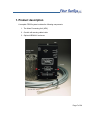
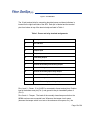
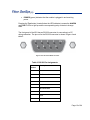
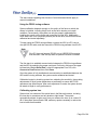
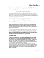
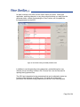
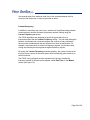
1
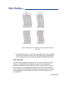
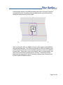
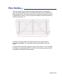
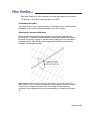
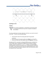
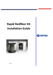
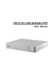
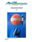
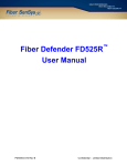
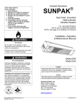
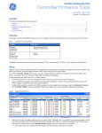
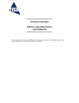
FD322 User Manual PM-ENG-012 Rev. C January 9th, 2012 © Copyright 2012, Fiber SenSys® all rights reserved. No part of this publication may be reproduced or transmitted in any form or by any means, electronic or mechanical, including photocopy, recording, or any information storage and retrieval system, without permission in writing from Fiber SenSys®, Inc., 2925 NW Aloclek Drive, Suite 120, Hillsboro, Oregon 97124, USA. This manual is provided by Fiber SenSys, Inc. While reasonable efforts have been taken in the preparation of this material to ensure its accuracy, Fiber SenSys, Inc. makes no express or implied warranties of any kind with regard to the documentation provided herein. Fiber SenSys, Inc. reserves the right to revise this publication and to make changes from time to time in the content hereof without obligation of Fiber SenSys, Inc. to notify any person or organization of such revision or changes. FD322TM is a trademark of Fiber SenSys, Inc. Fiber SenSys® is a registered trademark of Fiber SenSys, Inc. Windows® is a registered trademark of Microsoft Corporation. Fiber SenSys, Inc. 2925 NW Aloclek Dr. Suite 120 Hillsboro, OR 97124 USA Tel: 1-503-692-4430 Fax: 1-503-692-4410 [email protected] www.fibersensys.com Confidential – Limited Distribution Page ii Table of contents Table of contents iii Safety information 4 1. Product description 7 2. Site planning and preparation 14 3. Installation 22 4. Calibration 31 5. Maintenance 41 6. Troubleshooting 43 7. Network Integration 48 Appendix A. Product Specifications 60 Appendix B. Warranty Information 62 Index 63 Page iii Safety information Please read and keep these instructions and operate the product in accordance with the specifications outlined in appendix A. Please use only attachments and accessories that have been specified by the manufacturer, and refer all servicing to qualified service personnel. Safety terms Where appropriate, the following terms may appear in this manual: Caution Identifies conditions or practices that could result in damage to equipment or property, or possible loss of data or contamination of your files. Warning Identifies conditions or practices that could result in non-fatal personal injury. Danger Identifies conditions or practices that could result in loss of life or limb. Electrical safety The FD322 alarm-processing unit (APU) operates on 12-24 VDC. Do not use the APU if it: shows visible damage does not operate as expected has been subjected to prolonged storage under adverse conditions has been damaged during shipment Page 4 of 64 Do not put the APU into service until qualified service personnel have verified its safety. Class I laser product Each APU has two output ports that emit Class I laser radiation, as defined by IEC 60825-1 and CFR 21 subchapter J. Class I laser radiation is insufficient to constitute a hazard according to established limits. However, avoid direct eye exposure to the output of this product and to the open end of any optical-fiber cable connected to this product. The following stamp is found on the front panel of the APU: Fiber-handling precautions The optical fiber is made of glass and the ends of a broken fiber can be sharp and easily stick into your skin. Take appropriate glass-handling precautions. Never bend the optical fiber to a diameter less than 2 inches (5 cm). Smallerdiameter bends can cause damage to the optical fiber. Covers and panels To avoid personal injury, do not remove any of the product’s covers or panels. There are no user-serviceable parts inside and the warranty is void if the factory seal is broken. Do not operate the product unless the covers and panels are installed. Inspection The APU should be inspected for shipping damage. If any damage is found, notify Fiber SenSys and file a claim with the carrier. Save the shipping container for possible inspection by the carrier. Page 5 of 64 FCC Rules Note This equipment has been tested and found to comply with the limits for a Class B digital device, pursuant to Part 15 of the FCC Rules. These limits are designed to provide reasonable protection against harmful interference in a residential installation. This equipment generates, uses and can radiate radio frequency energy and, if not installed and used in accordance with the instructions, may cause harmful interference to radio communications. However, there is no guarantee that interference will not occur in a particular installation. If this equipment does cause harmful interference to radio or television reception, which can be determined by turning the equipment off and on, the user is encouraged to try to correct the interference by one or more of the following measures: Reorient or relocate the receiving antenna. Increase the separation between the equipment and receiver. Connect the equipment into an outlet on a circuit different from that to which the receiver is connected. Consult the dealer or an experienced radio/TV technician for help. Page 6 of 64 1. Product description A complete FD322 system includes the following components: 1. The Alarm Processing Unit (APU) 2. Conduit with sensing cable inside 3. Optional NEMA 4X enclosure Page 7 of 64 Figure 1. APU, conduit, stainless steel wire ties, and sensing cable The alarm processing unit The APU is an electro-optical Instrument that uses optical fiber as a distributed sensor for detecting intruders who are trying to cut, climb or crawl under a fence. The APU can be calibrated, or tuned, to disregard non-threatening phenomenon such as wind and animals, thus reducing nuisance alarms. When an intruder is detected, the APU sends out an alert via terminal contacts that can be used to switch on lights, cameras, sirens, or to signal an alarm panel (see figure 2). Caution Each APU supports two zones. The sensing cable for each zone connects to the APU using fiber-optic ST connectors. Using other types of connectors may reduce the product’s performance and/or damage it. Page 8 of 64 Figure 2. FD322 alarm relay contacts schematic (unpowered state) The APU also has an IP port, over which alarms can be sent to a head end for further processing and action. The APU can also be ordered with an optional weatherproof National Electrical Manufacturers Association (NEMA) enclosure. APU connections and indicators The FD322 APU has several input/output connectors. There are two optical connectors (labeled Input and Output) for each channel/zone. In addition, each APU has a terminal connector strip for DC power, alarm and fault relays and tamper input. There is also an RS-232 connector and an RJ45 connection for Ethernet (see figure 3). Page 9 of 64 Figure 3. The FD322 APU The 12-pin terminal strip for connecting electrical power and alarm indicators is located on the right-hand side of the APU. Each pin is labeled and the terminal pins from bottom to top of the terminal strip are listed in Table 1. Table 1. Power and relay terminal assignments Terminal Description 1 +12 - 24 VDC 2 Ground 3 Tamper Input 4 Tamper Input 5 Fault Relay Output 6 Fault Relay Output 7 Channel A Normally-Closed Relay Output 8 Channel A Relay Common 9 Channel A Normally-Open Relay Output 10 Channel B Normally-Closed Relay Output 11 Channel B Relay Common 12 Channel B Normally-Open Relay Output Pins 1 and 2 – Power: 12 to 24 VDC is connected to these terminal pins. Positive lead is the bottom-most pin (Pin 1) and ground is the pin immediately above it (Pin 2). Pins 3 and 4 – Tamper: The leads of the normally closed tamper switch on the NEMA enclosure are connected here. Whenever the tamper circuit opens (because the tamper switch is not set or the enclosure door opens, etc.), the Page 10 of 64 alarm relay activates and remains activated until the circuit closes again or the tamper feature is disabled. Pins 5 and 6 – Fault: These pins are used to connect the fault relay to a remote indicator. The normally closed fault relay contacts open if there is a loss of optical power or if the optical fiber is cut. The contacts are open when the APU is unpowered. Pins 7 and 8 – Channel A, normally closed alarm contacts: When the APU determines that an alarm condition in the channel is met, the contact opens. When the system is powered down, this contact is open. Pins 8 and 9 – Channel A, normally open alarm contacts: When the APU determines that an alarm condition in the channel is met, the contact closes. When the system is powered down, this contact is closed. Pins 10 and 11 – Channel B, normally closed alarm contacts: When the APU determines that an alarm condition in the channel is met, the contact opens. When the system is powered down, this contact is open. Pins 11 and 12 – Channel B, normally open alarm contacts: When the APU determines that an alarm condition in the channel is met, the contact closes. When the system is powered down, this contact is closed. Caution Do not apply AC voltage to these pins. The alarm relay contacts are rated for DC voltage only (100 mA at 24 VDC). LED indicators. LED indicators for each available channel are found on the front panel of the module. FAULT (red) indicates a loss or significant degradation of returning optical power. EVENT (yellow) indicates a disturbance or event has been detected in the sensor cable. ALARM (red) indicates that an alarm condition has occurred. Page 11 of 64 POWER (green) indicates that the module is plugged in and receiving power. Pressing the Test button (located below the LED indicators) causes the ALARM and FAULT LEDs to light up and the corresponding relay contacts to change state. The front panel of the APU has an RS-232 connector for connecting to a PC during calibration. The pin-out for the RS-232 connector is shown in figure 4 and table 2. Figure 4. Pin-out for the RS232 connector Table 2. RS-232 Pin Assignments Pin Number Description 1 No connection 2 T x D transmit 3 R x D receive 4 No connection 5 Ground 6 No connection 7 RTS 8 CTS 9 No connection Page 12 of 64 Note: Connections to the APU’s RS-232 interface should use straightpin DB-9 serial cable Sensor cable The FD322 sensor is a thin strand of multimode optical fiber in a 3-mm cable housed inside half-inch grey conduit that is attached to the fence using stainlesssteel wire ties. The conduit serves two purposes. First, it protects the cable from threats such as UV exposure and direct cutting. Second, it allows the cable to move freely when an intruder shakes the fence. When an intruder disturbs the fence and moves it slightly, this slight vibration is sensed by the fiber/cable inside the conduit. The APU measures the amount as well as the frequency of the vibrations and (using proprietary algorithms) determines whether the shaking is caused by an intruder or some “nuisance” such as wind or animals. The fiber, conduit, stainless-steel wire ties, connector kits, and installation tools necessary for a complete install are all available through Fiber SenSys. Contact the factory for part numbers, kits, and pricing. Page 13 of 64 System block diagram A block diagram of the FD322 and its system components is shown in figure 5. Figure 5. FD322 system block diagram 2. Site planning and preparation Successful installation and operation of the FD322 is accomplished by understanding all of the security needs of the site being protected as well as proper deployment of the sensor cable. This chapter outlines the site-planning and threat-assessment procedure. Page 14 of 64 Prior to installing the FD322 and deploying the sensor cable, carefully assess the site for all potential threats and security needs as well as system maintenance requirements and equipment compatibility. If, for example, the FD322 alarm relays are wired to activate remote video equipment, the maintenance requirements and compatibility of the FD322 and video equipment should be considered. Fenced perimeters The six threats against a fence line are: Going over the top of the fence 1. Climbing the fabric 2. Climbing posts 3. Ladder-assisted climbing Going through the fence 4. Cutting the fabric Going under the fence 5. Digging under the fence 6. Lifting the fence fabric Successful protection against these threats depends on the proper deployment of the sensor cable and calibration of the APU. Fence sensor cable deployment guidelines When determining a strategy for protecting the site, there are three important issues regarding the sensor cable: 1. The sensor cable detects movement, so you want to install it in such a way that it vibrates when an intruder is present, but not when non-threatening things such as wind or animals are present. 2. The sensor cable has the same level of sensitivity throughout its entire length. Areas that are easily vibrated by intruders need less coverage by the sensor/conduit than areas that are not as easily vibrated. Page 15 of 64 3. The APU does not distinguish the intruder’s location along the sensor cable. To localize the intruder, separate the perimeter into zones that are small enough to be quickly checked when an intruder trips the alarm. Make the fence “quiet” Wind is one of the biggest sources of nuisance alarms. The best way to avoid these notifications is to make the fence “quiet” when the wind blows. Here are some specific things you can do to accomplish this: Install high-quality fence o Deploy uniform zones o Within a zone the type, quality, and tension of the fence should be uniform. Keep the fence line clean o For chain link fences, re-tension the fence fabric if it is loose and add more ties to the fence fabric and the fence signs (as necessary) to prevent them from slapping or banging the fence and posts when the wind blows. Keep the area on both sides of the fence clear of tree limbs and other vegetation that might brush against the fence when the wind blows. Clear the outside perimeter of objects that might be used as climbing aids, such as trees, large rocks, etc. There should be no places where an intruder could easily crawl or dig under the fence. Pay attention to man-made and natural barriers o Buildings, structures, waterfronts, and other barriers used in place or as part of the fence line should provide adequate protection against intrusion. Ensure there are no windows, doors, openings, or unguarded means of access. For a chain link fence to be most effective against intrusion, it must conform to the following nine specifications: 1. Use steel, nine-gauge fabric mesh with maximum openings of 5 in (12 cm), tensioned consistently across each zone. 2. Use nine-gauge fabric ties with at least four ties evenly spaced on each fence post. Page 16 of 64 3. If it exists, the top guard outrigger should be angled away from the protected area and covered with at least three strands of tensioned barbed wire. 4. The top of the fence fabric should be at least 7 ft (2.1 m) above the ground. 5. Pin or weld all posts, supports and hardware to prevent disassembly of the fencing or removal of its gates. Locate all posts and structural supports on the inner side of the fencing. Use concrete to secure posts in the ground to prevent shifting, sagging, or collapse. Additionally, place posts every ten feet or less. 6. The use of “hog rings” and aluminum wire is not recommended. 7. Install taut reinforcing wires interwoven or affixed with fabric ties along the top and bottom of the fence for stabilization of the fabric. 8. The bottom of the fence fabric should be less than 2 inches (5 cm) above firm soil or buried sufficiently in soft soil. 9. Ensure that culverts under or through a fence consist of pipe 10 in (25 cm) in diameter or less. If a larger pipe is used, properly grate and equip with sensors to prevent access. Sensor deployment Figure 6 shows the basic recommended loop-back installation of the fiber-optic sensor for the FD322. In this configuration the sensor is routed down the zone, below the top of the fence, then looped back (approximately ¼ of the fence height) above the bottom of the fence. This maximizes the probability of detecting intruders that are trying to climb over, crawl under, or cut through the fence. Install the sensor on the secured side of (inside) the fence and overlap it from one zone to the next to avoid any gaps in sensor coverage. For a standard loopback configuration the fence should be less than 8 ft (2.4 m) high. Taller fences may require repositioning of the sensor cable or adding an additional sensor loop. Page 17 of 64 OVERLAP SENSORS AT ZONE ENDS LOOP SPACING 8” +/- 2” Figure 6. Sensor cable deployment types Install service loops at regular intervals to allow the sensor cable to be re-spliced as necessary without having to remove and then redeploy the entire cable. A good rule of thumb is to add a service loop about every 300 ft (91.4 m) and to put an extra 5 ft (1.5 m) of cable in each loop (see figure 7). SERVICE LOOP WIDTH 8” +/- 2” Figure 7. Adding a service loop The standard loop-back configuration is an economical way to provide reasonable protection for most perimeters. The following techniques provide additional protection: Page 18 of 64 1. Run the fiber sensor between the fence fabric and the fence posts. 2. Add extra loops of sensing cable to reinforced panels, as shown below in figure 8. Figure 8. A loop of extra sensor cable on reinforced sections increases sensitivity. 3. Use additional loops of sensor cable on posts. When there are outriggers, extend the loops to the top of the outrigger to add protection against intruders climbing the fence posts (see figure 9). Page 19 of 64 Figure 9. For extra security use additional loops of sensing cable for posts and corner posts. 4. Do not attach the sensor to coiled razor wire because razor wire is unstable and subject to movement in the wind. Protect high-security perimeters with razor wire atop the fence using the Fiber SenSys FD33X/34X/525 product. APU deployment The FD322 APU is designed for deployment on or near the fence line, typically outdoors, in a NEMA enclosure hung from the fence or mounted near the protected area. Because all optical fiber is sensitive, mount the APU in an area free of vibration to avoid generating nuisance alarms. If the fence on which the APU is mounted is prone to vibration (resulting, for example, from wind or traffic) it is acceptable to mount the APU enclosure on a pole or standoff next to the fence (figure 10). Page 20 of 64 Install a tamper switch on the NEMA enclosure and mount it securely to prevent unauthorized access. If possible, select a shaded location to avoid excessively heating the enclosure and the APU inside. Figure 10. Mounting the APU in a NEMA enclosure, on a pole next to the fence. When mounting the APU in a NEMA enclosure, use an outdoor-rated NEMA 4X box with steel back plate. The CD that comes with the APU has a drawing (with a PDF extension) that can be used to locate the positions of holes to be drilled in the back plate. Simply print a copy of the drawing, tape it to the back plate, and drill at the marked holes (located at the four corners). These holes will then lineup with mounting holes in the APU housing, making it easy to securely hold the APU inside the NEMA enclosure. Page 21 of 64 3. Installation Sensor installation Ultimately, how the FD322 is installed and deployed is up to the end user. Fiber SenSys does not recommend or mandate one particular installation setup over another. However, the general procedure for installing the FD322 is as follows: 1. Create a security plan, including the location of the APU, provision of electrical power, routing of sensor cable, insensitive leads, and relay or TCP/IP connections. 2. Determine the number of zones. 3. Create a strategy for protecting gates. 4. Determine the amount of cable needed. 5. Deploy the cable. 6. Connect the sensor cable to the appropriate APU channel. Planning the site When developing the site plan take note of these characteristics: The length of the fenced perimeter (not including the gates) The number and length of gates The number of reinforced sections and their lengths Planned locations of the APU(s) Power requirements including usage required by the APU(s) The width of roadways or walkways through the gate(s) Keep a detailed list of these factors and their associated numbers. You will use them to calculate the amount of cable required later on in the procedure. Page 22 of 64 Number of zones The number of zones is determined partially by the size of the location and the ability to respond quickly to intruders. Other factors include whether video surveillance will be used (requiring a separate zone for each camera), or whether there are any remote sections of the site that must be monitored, in addition to the main locale. Protecting gates Gates are designed to move, so they can be the source of nuisance alarms unless the installation is performed with the following points in mind: Secure all gates to avoid as much un-intended movement as possible. This prevents them from swinging on their hinges, striking restraining posts, locking mechanisms, or their own latches during high-wind conditions. Gates that are routinely opened for authorized access and that are equipped with a sensor cable should be installed with an alarm-disabling circuit. Establish a separate zone for all gates in order to maintain a secure perimeter while a gate is open. In addition, reinforce sections of the fence leading to the gate(s) by adding additional structural support or posts. Separate gate hinge posts and fabric supporting posts as necessary. This is recommended to prevent or reduce vibrations transmitted from the gate to the sections of the fence with active sensor cable. Page 23 of 64 There are several ways to deploy the sensor cable on gates. For a swinging gate, the simplest method is to run the cable/conduit from the fence fabric to the gate and loop it back. The sensor cable is then routed below the gate and buried in hardened PVC conduit 1 ft (0.3 m) below the roadway to make it insensitive to vibrations (see figure 11). Figure 11. Installing the sensor on swinging gates. In addition to swinging gates, Fiber SenSys offers various approaches to protecting sliding gates. For information about these solutions, contact the factory. For gates that do not require protection, bury the cable at least 1 ft (0.3 m) below the roadway, routed through rigid PVC conduit, thus creating a gate bypass that is insensitive to vibration from the roadway. Page 24 of 64 Determining the amount of cable needed To determine how much sensor cable is needed it is necessary to know the following: Length of the fenced perimeter (not including the gates) Number of gates and the length of each gate Number of reinforced sections and their lengths Distance from the fence to the alarm processor Widths of the roadways or walkways through the gate(s) Deploying the cable Caution Ensure that no zone covers more than one type (or quality) of fence. Optical fiber is fragile because it is made of glass. It will break if it is twisted or bent into too tight of a radius. The following precautions should be kept in mind when handling fiber-optic cable: Caution Be sure to follow these precautions, as failure may result in damage to the fiber and degraded or poor system performance. Do not pull the cable by the connectors as this can damage the connectors and result in degraded performance. Avoid twisting the cable or bending it into a radius tighter than 2 in (5 cm). Tighter bends might damage the fiber or break it. Dirty connectors can damage the APU. Keep the connectors capped until you are ready to make a connection, and always clean them with an approved Page 25 of 64 fiber-optic cleaning kit. After cleaning you should also inspect the connectors for damage or dirt before connecting them to the APU. Terminating the cable The FD322 uses ST-type optical connectors. Termination kits for installing these connectors on the sensing cable are available from Fiber SenSys. Attaching the sensor to the fence Attach the conduit to the fence using stainless-steel wire ties (available from Fiber SenSys). Thread the wire tie through the fence fabric, bend it back around the conduit as shown in figure 12, and then twist it tightly (but not so tight that it kinks the conduit). Fiber SenSys sells a specialized tool that twists the tie by means of a simple pulling motion. Figure 12. Attaching the conduit to the fence with a wire tie. When attaching the conduit to chain link fence fabric, secure the cable to the fabric every 1 ft (0.3 m or about 4 squares of most meshes). Secure the conduit on the joint or intersection between links of the mesh in order to prevent movement of the cable and minimize any susceptibility to tampering (see figure 13). Page 26 of 64 Figure 13. Spacing the wire ties. Installing the APU Caution Use of control or adjustments, or performance of procedures other than those described herein may result in exposure to hazardous laser radiation. Once the conduit/sensor has been deployed on the fence you need to connect it to the APU. To do this, use the following steps: Terminate both ends of the sensing cable with ST-type optical connectors. Connect one end of the sensing cable to the Output port of the APU. Connect the other end of the sensing cable to the Input port of the APU. Generally the APU is mounted in a fiberglass NEMA enclosure (available from Fiber SenSys), which is designed to be waterproof and resistant to weather extremes. The APU is rated to 70° C (131° F). However, it is recommended (when possible) to locate the APU indoors or in a shaded area when installed in hot climates. When locating the APU away from the protected perimeter, ensure that the sensing cable that stretches between the APU and the perimeter cannot be disturbed so as to cause alarms. Page 27 of 64 Mounting the enclosure The NEMA enclosure from Fiber SenSys measures 16.5 in x 14 in x 8.3 in (42 cm x 37 cm x 21 cm). Four tapped holes on the back of the enclosure allow for mounting with 10-32 screws. Fiber SenSys provides a mounting hardware kit with each enclosure for this purpose. The kit contains four mounting pads and four 10-32 screws as well as mounting instructions. In all cases, mount the APU so it is free of vibration, which can cause nuisance alarms. Wiring the APU Whenever the APU is mounted in an enclosure there must be holes through which the conduit/sensor enters and exits. Once the conduit/sensor is fed through these openings you should seal them to prevent exposing the APU to dirt or moisture. The optical cables are secured as they are passed into the enclosure by routing them through box couplers (available from Fiber SenSys). With the Fiber SenSys NEMA enclosure, the optical cables must be routed through the strain reliefs along the back plate to prevent stress at either the input or output entryways and connectors of the APU. The use of similar strain reliefs is recommended for any enclosure in which the APU is mounted. Ensure the 2 in (5 cm) minimum radius is observed while routing optical cable to the APU. Although the conduit entryways are generally drilled into the bottom of the NEMA enclosure as shown in figure 14, they may be placed anywhere the application requires. Once the optical connections have been made, wire the APU for electrical power and relay connections. These connectors are located on the right-hand side of the APU. Page 28 of 64 Figure 14. Wiring the APU. It is recommended that power leads and relay leads be routed separately through the enclosure. Note: There may be a significant DC voltage drop in smaller diameter wiring. Ensure the input voltage at pin 1 is at least 12 VDC following installation, with the APU powered up. Page 29 of 64 To increase the security of the installation, it is recommended that either series or parallel resistors (known as supervisory resistors) be added to the relay wiring as necessary. This ensures that a closed contact condition cannot be simulated by shorting the external relay contact leads, and that an open contact condition cannot be simulated by cutting them or removing power. Install these resistors inside the NEMA enclosure as close to the terminal connector pins of the APU as possible. If the supply voltage fails, or the optical fiber is cut or disconnected, the fault relay contacts open, the normally closed alarm relay contacts open, and the normally open alarm contacts close. As a final step in the wiring procedure, connect the leads of the tamper switch to the tamper terminals on the APU (pins 3 and 4). Adding supervisory resistors Adding a series resistor to the normally closed alarm relay contacts ensures a closed-contact condition cannot be simulated by shorting the external alarm relay contact lead. A series-resistance value of 2.74 kilohms is recommended. Adding a parallel resistor to the normally open alarm relay contacts ensures an open-contact condition cannot be simulated by cutting the external alarm relay contact leads. A parallel-resistance value of 2.74 kilohms is recommended. With the FD322 properly installed, it is now ready for calibration. Page 30 of 64 4. Calibration Before it can be effectively deployed, the FD322 must be calibrated or “tuned.” The calibration process uses specialized software to set tuning parameters that enable the FD322 to effectively distinguish the differences between sensor signals caused by intruders and those caused by non-threatening things such as wind and small animals. The calibration process is also how the overall system gain or sensitivity is set. This section provides detailed information on the tuning parameters that are used to calibrate the system for your specific needs. The FD322 tuning software is found on the CD that is included with the APU. The installation disk contains: Setup.exe Install.msi Image (folder) User’s manual Printable mounting template Installation can be performed either by running SETUP.EXE or manually by copying the contents of the IMAGE folder to the location of your choice on your computer’s hard drive. For manual installation you must create your own start menu entries and shortcuts. Automatic Installation Run SETUP.EXE. The default installation path is C:\Program Files\Fiber SenSys\FD322 Tuning SW. This program writes data to a folder located within the program folder. If the computer is running User Account Control (Vista, Windows 7) the program will be prevented from writing data to this folder, so you must specify a location for the program that is not protected. Generally this means a location not under C:\Program Files. It is also possible to disable User Account Control. Manual Installation For manual installation, simply copy the contents of the IMAGE folder to a location on the hard drive. To run the program, double-click FD322TuningSw.exe. No other configuration is required, however you may wish to create a shortcut or start menu entry to facilitate launching the program. Page 31 of 64 The same issues regarding User Account Control discussed above apply to manual installations. Using the FD322 tuning software System calibration depends strongly on the quality of the fence on which the sensor is installed, including things such as the fence tension and overall condition. Consequently, the system can only be properly calibrated after installing the sensor on the fence and connecting it to the APU. Additionally, since each zone is on a physically distinct part of the fence, each zone must be calibrated and tested separately. To begin using the FD322 tuning software, connect the APU to a PC using a nine-pin RS-232 cable, and then launch the FD322 tuning software from the PC. Note: If the PC does not have an RS-232 port, a USB/RS-232 converter must be used. Fiber SenSys sells an optional converter if needed. The first step is to establish communication between the FD322 tuning software and the APU by selecting the proper serial port. Do this by clicking on the upper left-hand tab (labeled Serial Port), select the appropriate Com Port, click Connect to Com Port and then click Close. Once the system is fully installed and communication is established between the APU and the tuning software, the system can be calibrated and tested. Calibration begins by checking system loss, adjusting the sensitivity, then making adjustments to other system parameters as necessary to ensure the FD322 operates at top effectiveness. After each adjustment is made, the system should be tested at length to verify performance. Calibrating system loss System loss is a measure of the optical loss in the fiber-optic sensor, including the loss due to connectors and any breaks or tight bends. The system automatically adjusts its gain every time you measure the loss, up to a loss of 6 dB. If the system loss exceeds 6 dB, make any repairs necessary to reduce the loss to below that threshold. Page 32 of 64 To measure loss, select Terminal mode and then type CALIB. Type ML and, when prompted, type Y. This places the APU in the loss calibration mode and the following prompt appears: Cha Loss(dB)= xxx@ mm/dd/yy hh:mm This prompt lists the optical loss along with the date and time it was measured. To measure the current loss, simply shake the sensing cable vigorously for about ten seconds and then (within about two seconds after shaking the fiber) press the Test button for the correct zone (channel). After pressing the Test button, the status line changes to read: Cha Loss(dB)= xxx SAVED @ mm/dd/yy hh:mm The word SAVED indicates that the system has been successfully calibrated and the new loss setting (xxx) is displayed along with the current date/time. Repeat this procedure two or three times, ensuring that the loss measurement does not change by more than ±1 dB, and that the loss does not exceed 6 dB. Once the system loss has been calibrated for channel A the same procedure is used to calibrate channel B. If the loss consistently measures higher than 6dB you can use a test cable, that is known to be good, to determine if the excess loss is caused by a damaged APU or a damaged sensing cable. To do this, connect the test cable directly between the Input and Output ports on the APU and then follow the process just described (using Terminal mode and CALIB) for measuring loss. If the loss is still high, refer to the trouble-shooting section of this manual Tuning the zones To set the tuning parameters, select the APU parameter editor in the Modes tab (see figure 15). The tuning software defaults to channel A. If you want to tune channel B, click the button that’s labeled “Switch Channels” (located on the right side of the display, in the “Process” bar). Once the proper channel is displayed above the “Switch Channels” button, click the button labeled “Receive” to load the current tuning parameters from the APU. The header in the main body of the APU parameter editor shows the model number, serial number, manufactured date, and firmware. Below the header are the tuning parameters that are set in order to tune the APU. Change the tuning parameters as desired, but make certain not to select values outside the limits shown on the screen. Page 33 of 64 No data is written to the APU until the “Send” button is clicked. Closing the application, switching channels, or any other action that takes you away from the parameter editor, without first pressing the “Send” button, will not update the tuning parameters in the APU. Figure 15. Screenshot showing the FD322 parameter editor. In addition to receiving/sending tuning parameters, and switching from one channel (zone) to another, buttons in the “Process” bar can also be used for opening/saving spectral files. The APU has independent tuning parameters that can be adjusted to detect an intruder cutting the fence or climbing over it. For both the cut and climb processors, the available tuning parameters are shown in the following table. Page 34 of 64 Table 3. Tuning Parameters Parameter Enabled Sensitivity Event count Lowest frequency Function Turns the corresponding processor on or off. Note: turning off both processors will disable the APU. Adjusts the overall sensitivity Changes the number of “events” that must be generated to trigger an “alarm.” Defines a low-frequency threshold. Sensor signal below the low-frequency threshold is not used by the algorithms when detecting events/alarms. Sensitivity Adjusting the sensitivity of either the cut or the climb processor raises or lowers the overall sensitivity of that processor. Although raising the sensitivity level increases the likelihood of detecting an intruder, it also makes it more likely that something such as wind or animals might generate a nuisance alarm. When setting the sensitivity it is necessary to strike a balance so that the processor is sensitive enough to detect the sort of intrusions you are looking for, but not so sensitive that it triggers alarms from local nuisances. For these reasons, the sensitivity setting can only be determined through adjustment and subsequent system testing. Generally the processor sensitivity should be adjusted for the minimum value that adequately detects a simulated intruder, ensuring the system is no more sensitive than necessary. Event count One of the best ways to differentiate valid threats from nuisances is by the number of times a signal is generated in a given period of time. Generally, a nuisance such as an animal or tree branch doesn’t make consistent disturbances as an intruder does. The event count specifies the number of times an event must occur, within a specific amount of time, before the APU generates an alarm. For the event counter to increment, one event must be followed by a second event within five seconds, otherwise the event counter resets. In other words, if the event counter is set for three, this means at least three events must occur, each no more than Page 35 of 64 five seconds apart for a maximum total time of ten seconds between the first event and the third event, in order to generate an alarm. Lowest frequency In addition to sensitivity and event count, another tool for differentiating between nuisance alarms and real intruders is frequency-domain filtering using the Lowest Frequency parameter. The FD322 algorithms are designed to ignore all signals that occur at frequencies lower than the Lowest Frequency setting. This can help distinguish between real threats and nuisances because the sources of many nuisances have acoustic characteristics that are different from those of real threats. For example, wind noise tends to cause low-frequency signals. On the other hand, cutting and climbing the fence generate higher-frequency signals. By setting the Lowest Frequency parameter properly, the system can be tuned to ignore many sources of nuisance alarms while maintaining good sensitivity to actual intrusions. The FD322 tuning software provides a powerful tool to help visualize the frequency content of different sensor signals, called Real Time, in the Modes section (see figure 16). Page 36 of 64 Figure 16. Signal with low frequency content (top) caused by wind, and a signal with high-frequency content (bottom) caused by cutting the fence fabric. Page 37 of 64 Wind rejection The FD322 has built-in algorithms that reduce the probability of wind-generated nuisance alarms. Increase or decrease the effect of the wind-rejection algorithm by adjusting the Wind Rejection parameter. The wind-rejection algorithm works by effectively reducing the system sensitivity as wind speed (inferred from sensor signals) increases. As wind noise increases, the APU automatically lowers the processor sensitivity value in accordance with the wind rejection factor; a higher wind-rejection setting means a greater reduction in sensitivity for a given amount of wind-generated noise (see figure 17). Experimentation on the installed system is necessary to determine the proper wind-rejection parameter for a given site. Figure 17. The wind-rejection algorithm helps to avoid wind-related nuisance alarms by reducing the sensitivity as the wind increases. Page 38 of 64 System testing As the last step of the installation /calibration process, test the FD322 to determine its effectiveness. Zone detection System testing begins with reviewing the list of threats against the site. To determine the probability of detection (PD) for those threats, begin by simulating each threat. Perform each simulation 20 times and monitor the response of the FD322. For example, to determine the PD of an intruder climbing over the fence, have a volunteer climb over the fence in the same manner 20 times. Don’t tell the volunteer if an alarm is being generated to prevent them from using that knowledge to alter their simulated intrusion. Record the number of climbs that produce an alarm, and then divide this number by 20. Multiply the result by 100 to calculate the PD. If the PD is too low, adjust the sensitivity, event count, and low frequency parameters as necessary until the PD reaches the desired level (refer to the previous sections that discuss Sensitivity, Wind Rejection and Event discussed earlier in this chapter). Repeat this test for each installed zone/APU and record the results in your test log. Tamper test The tamper feature on APUs installed in NEMA enclosures must also be tested. Perform this test for each APU in a NEMA enclosure. 1. Verify that all alarms and alarm-indicating LEDs are reset. 2. Proceed to the first NEMA enclosure to be tested. Open the door and observe the tamper alarm at the APU (if the APU is connected to annunciator equipment, verify that the alarm registers there, too). The alarm should occur before a gap of more than 1/8 in (3.2 mm) exists between the door and the enclosure. 3. Record the results in your test log. 4. Close and latch the NEMA enclosure door. Page 39 of 64 Fault test This test verifies that the APU registers a fault condition when the optical sensor is broken. This test should be performed for each APU. 1. If the APU is mounted in a NEMA enclosure, open the enclosure door and set the tamper switch to the maintenance position by pulling on the actuator rod. 2. Ensure that no fault-, tamper- nor alarm-indicating LED is lit on the APU. 3. Disconnect the optical cable from the APU input connector. Verify that a fault alarm is generated. 4. Record the results in your test log. 5. Reconnect the cable and verify that the fault clears. Page 40 of 64 5. Maintenance General Operational site maintenance consists of routine inspections, fault isolation, and removal and replacement of faulty equipment. Preventative maintenance System visual inspection is recommended every 90 days: 1. Carefully inspect the sensor-cable conduit for integrity. Verify there are no cracks or kinks in the conduit. Also verify the cable is not pulled into a radius tighter than 2 in (5 cm) at any point. 2. Ensure the conduit is attached firmly to the fence. Add or replace wire ties as needed. 3. Inspect the integrity of the fence. Tighten any loose fence hardware and remove any foreign material from the fence fabric. 4. Ensure all APU LED indicators are normal (only the Power indicator LED is lit). 5. Check the optical connectors at the APU and ensure they are properly seated. Check the integrity of the conduit where it enters the enclosure and seal any cracks or splits (between the conduit and enclosure) to prevent moisture from entering the enclosure. 6. Open all APU enclosures and verify they are free of moisture. System performance test, recommended every 90 days 1. Perform the same simulated intrusions used when testing the system during installation and qualification. This may include both simulated climbs as well as simulated cutting. Simulated cutting can be done by taping on the fence with a screwdriver (the number of taps should correspond to the current Event Count setting). 2. Verify that an alarm is generated at the annunciator equipment. 3. Record the test results. Page 41 of 64 4. Reset the annunciator equipment. 5. Repeat steps 1 through 3 at various locations throughout the zone to verify zone protection. APU status check, recommended every 180 days 1. Using a PC with FD322 tuning software, connect to the APU utilizing the RS-232 cable. After selecting the correct com port, select Terminal mode. 2. Calibrate the system loss according to the procedural steps outlined in the section on “Calibrating system loss.” 3. Press <CR> several times and then type STATUS. Verify the following: Loss (dB) is less than 6 dB. Las (mA) is less than 40. Pwr (V) is between 12 and 24. 4. Record these values and compare to the values recorded at the last status check. There should be no greater than a 2 to 3 dB change in the loss value. A greater difference may indicate the presence of a faulty connector, excessively tight bend, broken/cut fiber, or some other defect in the optical system. If the APU becomes damaged the damage may result in high loss values. If you consistently get high loss and cannot find anything wrong with the optical fiber and/or connectors, you should try measuring the loss of a test cable. The test cable should consist of a short section of the optical sensing cable that is known to have good connectors at each end (the sensing cable does not need to be inside conduit). Measure the loss of the test cable following the same procedure outlined for measuring the loss of a sensor zone. If the loss measurement for the test cable is more than 2 dB, contact Fiber SenSys Tech Support. Page 42 of 64 6. Troubleshooting Figures 19 through 21 are troubleshooting flowcharts for some common situations. If the flowchart indicates the need to inspect the zone and adjust the sensing parameters, the system may be experiencing nuisance alarms. As a first corrective step, check the cut and climb sensitivity and adjust it for the lowest possible value that still gives complete intruder detection. This is determined through experimentation and testing (refer to the section on “Calibration”). Possible nuisance sources that should be considered include: • Wind • Animals • Birds • Loose cable ties • Loose fence fabric, fence-mounted signs or a clanging gate • Nearby aircraft, road traffic, trains, etc. • Large towers or structures that can resonate with the wind and create low-frequency oscillations One of the most difficult steps in countering nuisance alarms is identifying the source. The FD322 tuning software can help by providing visual identification of the nuisance signal frequency and waveform. Investigate and determine where the source of nuisance is coming from. Once the source is identified, take measures to reduce the effects of the source, including recalibration and retesting of the FD322 system. Page 43 of 64 Figure 18. Page 44 of 64 Figure 19 Page 45 of 64 Figure 20 Page 46 of 64 If the system has high loss you can isolate the problem to either the sensing cable or the APU. If the system has high loss because of the APU, then the APU is damaged and must be returned to the factory. If the system has high loss because of the sensing cable then the cable should be repaired. To distinguish between high loss in the APU and high loss in the sensing cable, use the following procedure: 1. Disconnect the sensing cable from the Input and Output ports on the APU. 2. Connect a test cable to the Input and Output ports on the APU. This cable is usually short (one or two meters long) and used specifically for this test. Make sure you know the test cable is good by first inspecting the connectors at each end with an inspection microscope. 3. Follow the regular procedure for measuring loss, as described in the section on calibration. a) If the loss measurement is high then the problem may reside in the APU. Before returning the APU to the factory, however, clean both ends of the test cable and repeat the loss measurement. If the loss is within specification, proceed to step 5, otherwise there is also excessive loss in the sensing cable – proceed to step 4. b) If the loss measurement is low the problem resides in the sensing cable – proceed to step 4. 4. High loss in the sensing cable can result from a cut, pinch, or excessively tight bend. It can also result from damaged/dirty connectors. Inspect the sensing cable carefully, as well as all the connectors, cleaning/repairing as necessary. 5. Once the sensing cable has been repaired and/or the connectors cleaned, and the loss measurement is within tolerance, return the system to service by connecting the APU to the sensing cable as before. If you believe the sensing cable is okay, and that the problem is with the APU, contact Fiber SenSys Tech Support. Page 47 of 64 7. Network Integration Introduction The FD322 incorporates communication options intended to increase the ease with which users can communicate with the system. The capability exists to plug an FD322 APU directly into a Local Area Network (LAN). XML Communication XML, or eXtensible Markup Language, is a protocol which focuses on preserving the content of data transferring across a network from one component to the next. With XML, users “tag” various pieces of data or messages to indicate the related semantics, thus creating what are referred to as XML “documents.” These tags go along with the information in the document as it is passed between components. This means that when one computer receives the data from another, it is able to reassemble the message or document content accurately. With the FD322, XML communications allow a network to receive status messages from the unit (such as alarm/intrusion, tamper or fault conditions, etc.) and allows for a controller to send device configuration commands to an APU. XML documents can be created in any text editor and sent via any program or utility capable of addressing the appropriate network port. A number of alarm annunciator programs already have IP addressing capability embedded. For users without such programs, any terminal emulation software may be used. IP Communication Each FD322 is fitted with a RJ45 connector for TCP/IP network connection. This connector is located on the top left of the APU (figure 21). Page 48 of 64 Figure 21: Ethernet connections on the top left of the FD322 Interfacing the APU to the LAN Note: This section presumes readers have a working knowledge of networks and network administration. Every TCP connection is defined by a destination IP address and a port number. An IP address, which is uniquely assigned to every device on a network, allows communications to occur between specific devices on the network as required. The port number represents a TCP data channel used to direct data flow to a specific location within an IP address. Both address and port parameters must be set properly in order for the APU’s TCP/IP communication to function properly. If the APU is being installed in a network that has Dynamic Host Communication Protocol (DHCP) functionality, its IP address will be automatically assigned when it is plugged into the network. Proceed to the next section to make this type of connection. If the network is set up for static IP addressing, the APU’s address Page 49 of 64 must be set manually. Proceed to the section entitled “Setting the IP Address of the APU” if this is the case. Connecting the APU to a Dynamic Host Communication Protocol (DHCP) Network Each FD322 APU comes from the factory with a default IP address of 0.0.0.0, making it ready for insertion into a Dynamic Host Communication Protocol type network. Once connected, the network server will assign an IP address to the APU. Note: Lantronix® DeviceInstaller installation software and help files are included with the APU product components. To connect the APU to a DHCP network, proceed with the following steps: 1. Connect a Category 5 (CAT 5) network cable from the APU to an available connection to the network. 2. Power the APU. 3. Launch Lantronix® DeviceInstaller from the host PC. 4. The software may automatically detect XPort devices. If not, clicking the Search button (figure 22) will allow the program to locate and display the XPort connected devices (see figure 23). 5. DeviceInstaller will display a list of XPort devices it finds in the left hand pane of its main menu screen; expand the list by clicking on the “+” symbols until a list of IP addresses appears. 6. Identify the APU you’re working with by matching its MAC address (or hardware address) with one of the XPort devices shown in the right pane of the main menu screen. The APU’s MAC address can be found on its serial number label. Note the IP address of the unit and proceed to the section entitled “XPort Network Setup” to define the unit’s port settings. Setting the IP Address of the APU For networks which are not based upon the DHCP scheme, the IP address of the APU must be set manually using any PC with the Lantronix® DeviceInstaller Software or through telnet port 9999. Page 50 of 64 Note: Lantronix® DeviceInstaller installation software and help files are included with the APU product components. To set the IP address using DeviceInstaller 1. Connect a Category 5 (CAT 5) network cable from the APU to a host PC. 2. Power the APU. 3. Launch Lantronix® DeviceInstaller from the host PC. 4. The software may automatically detect XPort devices. If not, clicking the Search button (figure 22) will allow the program to locate and display the XPort connected devices (see figure 23). Figure 22: Lantronix® DeviceInstaller screen with XPort devices and the Search Button identified. Note: The MAC address (or hardware address) of the APU is found on a removable label, which covers the RJ45 connector upon shipment from the factory. It also appears on the serial number label of the APU (the Hardware Address noted in figure 22). Page 51 of 64 5. By clicking on a specific XPort device, it is then selected for configuration, showing details about the device selected. Figure 23: Device Details screen for selecting XPort device 6. Select the Assign IP button, figure 23, from the upper left hand side of the screen. 7. The "Assignment Method" screen appears. From here select “Assign a specific IP address,” as shown in figure 24, then select the Next > button. Page 52 of 64 Figure 24: Assignment Method screen for assigning a specific IP address 8. When the "IP Settings" screen appears, enter the IP address to be assigned, at which point the Subnet mask and Default gateway fields are filled in automatically, as displayed in figure 25, then select the Next > button. Figure 25: IP Settings screen Page 53 of 64 9. When the "Assignment" screen appears (as shown in figure 26) press the Assign button to begin the process of assigning the new IP address. The Assignment status screen will show the progress of the current task, as seen in figure 27. Figure 26: Assignment screen with the Assign button Figure 27: Assignment screen with “Progress of task:” bar Page 54 of 64 10. Once the task has been successfully completed, click the Finish button. 11. To assign the "Subnet mask" and "Default gateway identifiers," repeat steps 3 through 9, from the Search function. Caution: Changing any other settings may disrupt operation of the device. For assistance with this, contact Fiber SenSys. XPort Network Setup The steps in this process are used to correctly assign XPort network connection details. This step is done once an IP address has been assigned using one of the procedures completed above. Note: Changes are accepted ONLY after the Apply Settings button is pressed. Simply pressing the OK button will NOT activate the changes. 1. Start Internet Explorer or other internet browser. 2. In the address box at the top of the internet browser screen, enter the IP address just assigned during the Lantronix® DeviceInstaller program setup, as in figure 28. Figure 28: Address bar showing entry of newly assigned IP address 3. When the XPort login screen appears (see figure 29) simply click the OK button, leaving the “User name” and “Password” fields empty. Page 55 of 64 Figure 29: The login screen with blank data fields 4. From the menu again, select "Channel 1, Connection, Channel 1". When the "Connection Setting" screen appears (see figure 30), verify or change the "Active Connection" drop down menu setting to “Auto Start.” Note: Change “Active Connection” to “Auto Start” only if static IP addressing is to be used. If your network assigns IP addresses dynamically (DHCP), the “Active Connection” setting must be “None.” Page 56 of 64 Figure 30: The Connection Settings screen Page 57 of 64 5. From the same screen seen in figure 30, the settings in the "Endpoint Configuration" section must be verified / adjusted to be appropriate for your network. Default settings for these parameters are as follows: “Local Port” 10001 “Remote Host” XXX.XXX.XXX.XXX “Remote Port” 10000 “Auto increment….” Unchecked The Remote Host parameter refers to the IP address of the host computer and must be changed to match that IP address. The port settings are compatible with default settings in Fiber CommanderTM, which is a PC-based head end program separately available from Fiber SenSys. As mentioned earlier, a port is simply a TCP data channel, and the Remote Port setting here refers to the port that Fiber Commander uses to communicate with the APU. Both the APU and head end program must be set up to use the same port; the range is 1-65535. The chosen port number is not critically important, although there are a few port numbers that are reserved, and your network may already have some ports in use. Your network administrator can assist you with proper selection of the APU and Fiber Commander Remote Port settings, although the defaults will work with most systems. The Local Port setting is not relevant to those systems using Fiber Commander as a head end; leave this setting at its default value in this case. However, for those systems employing a head end that actively seeks APUs that are connected to its network, the Local Port setting becomes relevant. In this case, the Local Port setting must be set to match the head end’s setting; the same range and other port limitations stated above apply. Again, your network administrator can assist you with proper selection of the Local Port setting. Note: The data for Local Port, Remote Host, and Remote Port is user dependent. Your IT system administrator can help with these settings. 6. Click the OK button to apply the changes. The “Done!” notation will appear again indicating the changes have been accepted. Page 58 of 64 7. Refer to the left-hand side menu again, and click “Apply Settings”. The status screen in figure 31 is displayed and the recently updated information is saved (the new settings will NOT be accepted until this step has been completed). Once the process has completed, the home page will be displayed, and at this time, Internet Explorer or the browser window can be closed, completing the assignment of correct Serial and Network settings. Figure 31: The status page for applying the newly assigned settings Ë The APU is now ready for TCP/IP network operation. Should assistance be required during this process, contact Fiber SenSys. Page 59 of 64 Appendix A. Product Specifications Parameter Specification Application Perimeter fence Sensor Installation Multimode optical fiber cable Passive, inert, intrinsically safe Resistant to EMI and corrosion -40 ˚C to +70˚C operating range (APU) -40 C to +85C operating range (sensing cable) Sensing cable in conduit Conduit attached to fence with wire ties Loop-back zone configuration Number of zones per APU 2 Max. sensing cable per zone 500 meters APU electrical power requirements Input voltage: 12-24 volts DC Power: 3 Watts (250 mA @ 12 VDC) Programming method RS-232 using PC Communications IP/XML Contact ratings: 28 to 14 AWG 100 mA, 24 VDC non-inductive Fault and alarm relays Light source Relay defaults when the APU is in secured status: Fault relay - Normally Closed (NC) Alarm relay - Normally Open or Normally Closed (NO / NC) Type = laser Average power = 2 mW max Wavelength = 1310 nm Class 1 laser Page 60 of 64 Parameter APU dimensions Specification Width = 5.6 in (14.3 cm) Length = 10.1 in (25.7 cm) Height = .94 in (2.4 cm) APU operating temperature -40 ˚C to +70˚C Humidity 0 to 90%, non-condensing Optical connectors ST, PC polish Insensitive lead-in fiber No Regulatory compliance CE, FCC Part 15 Class B, RoHS Product compatibility Fiber CommanderTM Page 61 of 64 Appendix B. Warranty Information A. Fiber SenSys warrants the Fiber Defender Model FD322 to be free from electrical and mechanical defects in materials and workmanship for a period of two years from the date of shipment. This warranty does not apply to defects in the product caused by abuse, misuse, accident, casualty, alteration, broken tamper seals, use of current or voltages other than those specified by Fiber SenSys, application or installation not in accordance with published instruction manuals or repair not authorized by Fiber SenSys. This warranty is made in lieu of any other warranty either expressed or implied. B. All returns will be tested to verify customer claims of non-compliance with the warranty described herein. If non-compliance is verified and is not due to customer abuse or the other exceptions described previously, Fiber SenSys will, at its option, repair or replace the FD322 and return to customer, freight prepaid. Contact Fiber SenSys and obtain an RMA number prior to returning a product. Fiber SenSys will pay for ground return freight charges only. The customer must pay for any other return shipping options. C. Fiber SenSys liability is limited to the repair or replacement of the product only, and not the costs of installation, removal or damage to user’s property or other liabilities. If Fiber SenSys is unable to repair or replace a non-conforming product, it may offer a refund of the amount paid to Fiber SenSys for such product in full satisfaction of its warranty obligation. Maximum liability to Fiber SenSys is the cost of the product. Page 62 of 64 Index A APU Connections ...................................................9 Deployment ..................................................20 General description ........................................8 LED indicators...............................................11 Number of zones ............................................8 Power and relaty terminal assignments.......10 Status check .................................................42 Wiring ...........................................................28 C Cable Deployment ..................................................25 Termination ..................................................26 Calibration and tuning ......................................31 Event count ..................................................35 Lowest frequency .........................................36 Sensitivity .....................................................35 System loss ...................................................32 Tuning the zones ..........................................33 Wind rejection..............................................38 F Fault test ...........................................................40 Fence Making quiet ................................................16 Protecting gates ...........................................23 L Laser classification ..............................................5 LED indicators ..................................................11 M Maintenance ....................................................41 N Network integration IP communication ....................................... 48 Setting the IP address.................................. 50 XML communication ................................... 48 XPort network setup ................................... 55 P Product description ........................................... 7 Product Specifications ..................................... 60 R Relay terminal assignments ............................ 10 S Safety Electrical ........................................................ 4 General information ...................................... 4 Terms............................................................. 4 Sensor Amount needed .......................................... 25 Attachment to fence ................................... 26 Cable............................................................ 13 Depolyment ................................................. 17 Handling precautions .................................... 5 Installation................................................... 22 Site Planning ....................................................... 22 Planning and preparation ............................ 14 Software Automatic installation ................................. 31 Manual installation ..................................... 31 Tuning.......................................................... 31 System Testing ......................................................... 39 Page 63 of 64 System block diagram.......................................14 T Tamper test ......................................................39 Trouble shooting Nuisance alarms ...........................................43 Troubleshooting ...............................................43 Tuning parameters ...........................................35 W Warranty Information ..................................... 62 Z Zone detection ................................................. 39 zones, number of ............................................. 23 Page 64 of 64