1
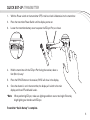
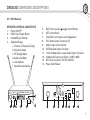
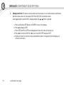
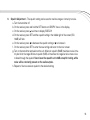
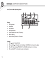
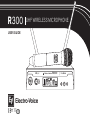
R300
UHF WIRELESS MICROPHONE
USER GUIDE
CHANNEL
MUTE
SYNC
MHz
EZsync
R300R300
Electro-Voice
Clear
ClearScan
SYNC
SET
1177
2
TABLE OF CONTENTS
1. Quick Set–up
• Receiver. . . . . . . . . . . . . . . . . . . . . . . . . . . . . . . . . . . . . . . . . . . . . . . . . . . . . . . . . . . . . . . . . . . . . . . . . . . . . . . . . . . . . . . . . . . . . . . . . . . . . . . . . . . . . . . . . . 4
• Transmitter. . . . . . . . . . . . . . . . . . . . . . . . . . . . . . . . . . . . . . . . . . . . . . . . . . . . . . . . . . . . . . . . . . . . . . . . . . . . . . . . . . . . . . . . . . . . . . . . . . . . . . . . . . . . . . 5
• Systems Operation. . . . . . . . . . . . . . . . . . . . . . . . . . . . . . . . . . . . . . . . . . . . . . . . . . . . . . . . . . . . . . . . . . . . . . . . . . . . . . . . . . . . . . . . . . . . . . . 6
2. Detailed Component Descriptions
• Receiver. . . . . . . . . . . . . . . . . . . . . . . . . . . . . . . . . . . . . . . . . . . . . . . . . . . . . . . . . . . . . . . . . . . . . . . . . . . . . . . . . . . . . . . . . . . . . . . . . . . . . . . . . . . 7-14
• Handheld Transmitter. . . . . . . . . . . . . . . . . . . . . . . . . . . . . . . . . . . . . . . . . . . . . . . . . . . . . . . . . . . . . . . . . . . . . . . . . . . . . . . . . . 15-16
• Bodypack Transmitter. . . . . . . . . . . . . . . . . . . . . . . . . . . . . . . . . . . . . . . . . . . . . . . . . . . . . . . . . . . . . . . . . . . . . . . . . . . . . . . . . 17-19
3. Guidelines and Recommendations For Best Performance. . . . . . . . . . . . . . . . . . . . . . . . . . . . . . . . 20-21
4. Troubleshooting Guide. . . . . . . . . . . . . . . . . . . . . . . . . . . . . . . . . . . . . . . . . . . . . . . . . . . . . . . . . . . . . . . . . . . . . . . . . . . . . . . . . . . . . . . . . . . . . . 22-23
5. Frequently Asked Questions. . . . . . . . . . . . . . . . . . . . . . . . . . . . . . . . . . . . . . . . . . . . . . . . . . . . . . . . . . . . . . . . . . . . . . . . . . . . . . . . . . . . 24-26
6. Components and Accessories.. . . . . . . . . . . . . . . . . . . . . . . . . . . . . . . . . . . . . . . . . . . . . . . . . . . . . . . . . . . . . . . . . . . . . . . . . . . . . . . . . . . . . . 27
7. Compatible Channel Frequency Groups.. . . . . . . . . . . . . . . . . . . . . . . . . . . . . . . . . . . . . . . . . . . . . . . . . . . . . . . . . . . . . . . 28-31
8. Specifications . . . . . . . . . . . . . . . . . . . . . . . . . . . . . . . . . . . . . . . . . . . . . . . . . . . . . . . . . . . . . . . . . . . . . . . . . . . . . . . . . . . . . . . . . . . . . . . . . . . . . . . . . . . . . 32-33
9. Certifications.. . . . . . . . . . . . . . . . . . . . . . . . . . . . . . . . . . . . . . . . . . . . . . . . . . . . . . . . . . . . . . . . . . . . . . . . . . . . . . . . . . . . . . . . . . . . . . . . . . . . . . . . . . . . . . . . . . . . . 34
10. Factory Service. . . . . . . . . . . . . . . . . . . . . . . . . . . . . . . . . . . . . . . . . . . . . . . . . . . . . . . . . . . . . . . . . . . . . . . . . . . . . . . . . . . . . . . . . . . . . . . . . . . . . . . . . . . . . . . . . 35
3
01
QUICK SET-UP: RECEIVER
1.
Do not connect the receiver to any other equipment yet!
2.
Connect the two Antennas to the receiver.
3.
Install the blades into the power supply, plug it into the back of the receiver,
and into an outlet.
4.
Press the POWER switch. Display will light up.
5.
Press and hold the
6.
When CLEARSCAN stops, the receiver will be set to the clearest channel.
7.
Mute the Audio Mixer channel where the receiver will be plugged in, or set it to minimum.
8.
Leave the receiver ON and connect it to the audio system using either the XLR connector or
¼-inch line level jack.
button until CLEARSCAN scrolls across the screen.
Receiver “Quick Set-up” is complete.
4
QUICK SET-UP: TRANSMITTER
1.
With the Power switch on the transmitter OFF, install two fresh AA batteries into the transmitter.
2.
Press the transmitter Power Switch until the display comes on.
3.
Loosen the transmitter battery cover to expose the EZsync Port, as shown.
R300
EZsync
ClearScan
SYNC
EZsync
CHAN
NEL
MUTE
SYNC
SET
R300
Clear
SYNC
SET
MHz
4.
Hold the transmitter with the EZsync Port facing the receiver, about a
foot (30 cm) away.*
5.
Press the SYNC Button on the receiver, SYNC will show in the display.
6.
nce the channel is set in the transmitter, the display will switch to the main
O
display and show RF and Audio Levels.
*Note: When performing EZsync, make sure lighting conditions are not too bright. Extremely bright lighting can interfere with EZsync.
Transmitter “Quick Set-up” is complete.
5
01
QUICK SET-UP: SYSTEMS OPERATION
1.
Set the mixer/amp gain.
2.
Talk or sing into the microphone or play the guitar at a normal volume. You
should hear audio coming out of the system.
3.
ou may have to adjust the gain (via the control next to the connector on the
Y
receiver back panel) to provide the best input volume for your mixer/amp.
Notes:
• See page 10 of this manual for more information.
• See Image 11 of the Quick Start Guide for gain control location.
“Quick Set-up” is now complete. Please enjoy your R300 system.
6
DETAILED COMPONENT DESCRIPTIONS
02
2.1 | R300 Receiver
RECEIVER CONTROLS, CONNECTORS
1. Power ON/OFF
2. SYNC Data Transfer Button
3. Infrared EZsync Window
4. Graphical Display
a. Channel or Frequency Display
b.Diversity Indicator
c. RF Strength Meter
d.Audio Level Meter
e. Lock Indicator
f. Squelch Level Indicator
EZsync
R300R300
Electro-Voice
5.
6.
7.
8.
9.
10.
11.
12.
13.
14.
Scroll Down and Up ( and ) Control Buttons
SET Control Button
ClearScan Control (press and hold button)
TNC Antenna Input Connectors (2)
Audio Output Volume Control
XLR Balanced Output Connector
¼ Inch Unbalanced Line Level Audio Output Connector
Unbalanced Output Level Switch (-10dB or 0dB)
DC Power Connector (12V DC, 500mA)
Power Cord Retainer
-10dB
Clear
ClearScan
SYNC
SET
ANTENNA B
8
MIN MAX
VOLUME
9
0dB
LEVEL
BALANCED OUT UNBALANCED OUT
10
11
12V
12
.500mA
13
ANTENNA A
14
8
7
02
DETAILED COMPONENT DESCRIPTIONS
2.1 | Receiver Setup & Operation
1.
Place the receiver and antennas where there is a clear line of sight to the area where the
transmitter will be used. Rotate the antennas to separate them by 90 degrees.
2.
I nstall the appropriate power connection blades into the power supply and connect the power supply cord to the receiver. Plug the power supply into an AC outlet. Push
the power button to turn the receiver on and confirm that it is on by checking the main display
screen.
-10dB
ANTENNA B
3.
8
MIN MAX
VOLUME
0dB
LEVEL
BALANCED OUT UNBALANCED OUT
12V
.500mA
ANTENNA A
Manual Channel Change
a. The and buttons allow you to scroll through the Channels. When the Channel
you desire is displayed, stop scrolling.
b.After 2 seconds the displayed channel number will start to flash.
c. The number will stop flashing and the new channel is installed.
d.Turn on the transmitter and hold the EZsync port facing the receiver EZSync port,
about a foot (30 cm) away, as described on page 5.
continued on next page
EZsync
SYNC
R300
ClearScan
EZsync
R300
Clear
SYNC
SET
CHAN
NEL
MUTE
SYNC
SET
MHz
e. Press the SYNC button on the receiver to transfer the channel information.
f. The receiver will display SYNC until the data is transferred, then return to the main screen.
g.The transmitter display screen will now show the new channel and frequency.
NOTE:
1. If the channel data was not transferred to the transmitter after 5 seconds, the receiver
will display ERROR. Be certain that the transmitter is On and the EZsync port is facing
the receiver and try again.
2. If the data still does not transfer, try new batteries, or move the unit to a shaded area
away from direct sunlight or bright lights before trying again.
continued on next page
9
02
DETAILED COMPONENT DESCRIPTIONS
4.
ClearScan: This feature automates the process of finding a clear channel.
a. .To scan for the clearest channel in a group, press and hold until CLEARSCAN
appears in the display, then release the button.
b.When the scan is complete, the display will show the clearest available channel.
c. Use the SYNC button to transfer the new channel as in step 3.
5.
During set up make sure the mixer or amplifier input used for the R300 is muted or turned down
to a minimum level.
6.
Plug an audio cable (not supplied) into the 3 pin XLR or ¼-inch TRS output of the R300.
Note: 10
The XLR connector is the preferred connection since the output is balanced and will be
more immune to noise for longer runs of cable although either can be used with good
results. Set the balanced output level on the back panel to 12 o’clock (midway in the
range) to start and adjust later if necessary. If the ¼-inch unbalanced output is used, start
with adjustment switch in the -10dB setting.
continued on next page
7.
With the transmitter on, speak into the microphone or play the guitar. Turn up the level on the
mixer or amplifier until you are able to hear the desired signal. If no audio is present, repeat
setup and refer to the troubleshooting section.
Note:
8.
It may be necessary to adjust the receiver output until the volume level from the wireless
system approximates the level of an equivalent wired microphone/instrument.
DISPLAY The main display can be adjusted to display the Channel number or the Frequency.
Note: At any time the item not selected for the main display can be shown for 5 seconds by
pushing the SET button once.
a. Press and hold the SET button until DISPLY shows in the display.
b.Press SET and FREQUENCY or CHANNEL will flash in the display.
c. Press for FREQUENCY or for CHANNEL and press SET.
d.Display will return to the main screen and the selected item will be displayed.
e. At any time the item not selected for the main display can be shown for 5 seconds by
pushing the SET button once.
continued on next page
11
02
DETAILED COMPONENT DESCRIPTIONS
9.
hange Lock-Out This feature can be useful when the receiver is in a location where unauthorized
C
personnel have access to the receiver. With the LOCK ON, the channel cannot
be changed and the word LOCK is displayed when the or button is pushed.
a. Press and hold the SET button until DISPLY shows in the display.
b.Press to display LOCK.
c. Press SET and ON or OFF will be displayed to show the status of the lock-out.
d.Press to turn the LOCK ON or to turn the LOCK OFF and press SET.
e. Display will return to the main screen and padlock symbol in the upper left of the display will
show the lock status.
12
continued on next page
10. Squelch Adjustment – The squelch setting can be used to maximize range or immunity to noise.
a. Turn the transmitter off.
b.On the receiver, press and hold the SET button until DISPLY shows in the display.
c. On the receiver, press two times to display SQELCH.
d.On the receiver, press SET and the squelch setting in the middle right of the screen (SQ
10dB) will flash.
e. On the receiver, press to decrease the squelch setting or to increase it.
f. On the receiver, press SET to enter the new setting and return to the main screen.
g.Turn on the transmitter and walk test the unit. Maximum squelch (50dB) maximizes noise immunity but limits the range. Minimum squelch (5dB) will maximize the range but allow more noise
to break through the squelch. Never leave the squelch set to 0dB except for testing, white
noise will be constantly present on the audio outputs.
h. Repeat to fine tune receiver squelch to the desired setting.
13
02
DETAILED COMPONENT DESCRIPTIONS
2.1.2 | Receiver Main Operating Screen
Display:
1. RF Signal Meter
2. Audio Meter
3. Lock Indicator
4. No Signal Indicator
5. Channel Number (01 to 32) or Frequency
6. Squelch Setting
7. Antenna Diversity Status A or B antenna
Controls:
1. Press or to change channels
2. Press and hold for 3 seconds starts ClearScan, CLEARSCAN scrolls across the display
3. Press SET once to display FREQUENCY or CHANNEL, whichever is not showing
4. Press and hold SET for 3 seconds to access settings menu
14
2.2 | Handheld Transmitter
HT-300 CONTROLS, CONNECTORS AND INDICATORS
1. Microphone Element
2. Backlit LCD Display
a. Channel
b. Frequency
c. Battery Level
d. Mute Indicator
3. EZSync Infrared Port
4. Battery Cover – Screw type
5. Battery Compartment – Two AA Batteries
6. On/Off/Mute button
15
02
DETAILED COMPONENT DESCRIPTIONS
2.2 | Handheld Transmitter Setup & Operation
1. Insert Batteries.
a. Remove the battery compartment cover by unscrewing it completely.
b. .Insert two AA batteries as shown, sliding one up into the housing to make room for
the other making sure to follow polarity, as marked.
2.
Turn the unit on by pressing and holding the on/off button for 3 seconds, and the display will
light up.
3.
If a new channel is desired, use EZsync as in Section 2.1 and close battery compartment.
4.
Verify reception.
a. With the transmitter and receiver on a matching Channel, the main receiver display
should be indicating a RF signal on the bar graph.
b. Speak into the microphone and the Audio Meter bar graph should indicate audio
signal presence.
c. .If the level meters do not show reception, make sure the channels are matching and
refer to the troubleshooting section.
16
5.
ute Function – press and hold on/off button for 2 seconds until MUTE appears in the LCD
M
display and sound mutes. Repeat to turn mute off.
2.3 | Bodypack Transmitter
1
3
4
7
1
2
5
6
9
8
BP-300 CONTROLS, CONNECTORS AND INDICATORS
1. Antenna – Flexible ¼ wave antenna
2. Power On/Off/Mute Button
3. TA4 Microphone Connector
4. On/Mute LED – Green when transmitter is on, Red when muted
continued on next page
17
02
DETAILED COMPONENT DESCRIPTIONS
2.3 | Bodypack Transmitter continued
5. LCD Display
a. Channel
b. Frequency
c. Battery Level
d. Mute Indicator
6. EZsync infrared window
7. Battery Compartment Latch – push down latch and slide cover as shown
8. Two AA Battery Compartment – follow polarity as marked
9. LAV/INS Gain Switch
18
2.3.1 | Bodypack Transmitter Setup & Operation
1. Insert Batteries
a. O
. pen the battery compartment by pressing in on the latch and sliding the door down.
b. Insert two AA batteries with + and – as indicated.
c. Close the battery door by pushing up.
2.
urn the unit on by pressing and holding the on/off button for 3 seconds, and the LCD display
T
will light up. If channel has not been set, set channel according to 2.1.
3.
Microphone/Guitar Operation.
a. For Lapel the gain switch should be in the LAV position.
b. For Headworn Microphones the gain switch should be in the INS position.
c. If lapel microphones are too sensitive and the audio meter on the receiver is reaching the
peak, put the gain switch in INS to lower the gain.
d. For guitar operation using the optional R300GTRCBL cable, the gain switch should
be in the LAV position for passive pickups, and in the INS position for active pickups.
Should the output of the passive pickups be too high in the LAV position, switch to the
INS position for reduced transmitter input gain.
4.
Mute Function – press and hold on/off button for 2 seconds until MUTE appears in the LCD
display, On LED turns red, and sound mutes. Repeat to turn mute off.
19
03
GUIDELINES AND RECOMMENDATIONS For Best Performance
Compatibility
The transmitter and receiver must be of the same frequency band and set to the same channel in order
to work together. The R300 is available in four frequency bands, A, B, C and E (Europe only). The band
information is available in the serial number label on the receiver, the serial number label on the handheld
transmitter, and on the back panel label on the bodypack.
Using Multiple Wireless Systems
If three or more R300 systems and/or other UHF/VHF wireless systems are being used in the same
location, proper frequency coordination is necessary to avoid interference. Some channels in the R300
are designed to work together, see the channel groups in the back of this guide for more information.
Contact your dealer or Electro-Voice for assistance if you are planning more systems or using the R300
with other wireless equipment.
Multiple Systems and R300
The ClearScan function can be used to set up any two R300 systems. Just scan with the first unit
receiver, set the transmitter to that clear channel and leave it on. Then scan the second unit receiver for
another clear channel. If 3 or more systems in the same frequency band are used in the same room, put
all of the channels in the same group as indicated by the channel groups on page 28-31.
Potential Sources of Interference
There are many potential sources of interference for your wireless system. Any electronic product
that contains digital circuitry including digital signal processors (reverb/multi-effects units), electronic
keyboards, digital lighting controllers, CD and DVD players, and computers, all emit RF energy that can
20
adversely affect the performance of your wireless system. It is always best to place the receiver as far away as
possible from these devices to minimize potential problems.
Analog and Digital Television stations can also interfere with your wireless system. The R300 is designed to
operate over 16MHz of RF bandwidth, which covers 3 US TV stations. If two of the three stations are used
in your area, it will severely limit the number of systems that will operate together and you should be using a
different band.
Battery Recommendations
Fresh AA alkaline batteries from a quality manufacturer will yield the best performance from your R300
transmitters. If sound quality degrades during use, it may be the result of a weakening battery.
Receiver and Antenna Placement
Do not place the receiver near a large metal object or surface. Locate the receiver as close as possible to the
area where the transmitter will be used. Ideally, position the receiver/antennas within sight of the transmitter.
When using multiple systems, do not allow antennas to cross or touch each other.
Transmitter and Antenna Distance
Keep all transmitters at least 3 meters (10ft) away from the receivers and antennas for best operation. If
possible, mount the receiver antennas 3 meters (10ft) above the stage so transmitters can not come too close.
21
04
TROUBLESHOOTING GUIDE
Problem
Possible Causes
No audio and no display on
the receiver
Receiver is off
Transmitter is off
Make sure that the power supply is properly
connected and the on/off button is in the on position.
Turn on transmitter power switch.
No audio and no RF
signal indicator on the
receiver display
Transmitter is on a different channel or is
a different band
Check band information on serial number label and
match to receiver, reset channel (see section 2.1).
No (or dead) battery in transmitter
Faulty battery contacts
No Audio with good RF
signal indicator
Microphone not connected
Insert fresh batteries in transmitter.
Clean and or bend contacts to improve connection.
Check the TA4F connector on the bodypack or the
detachable microphone element connection on the
handheld. If possible, try another microphone.
Press and hold On/Off button to stop Mute.
No (or low) Audio with
good RF signal and Audio
indicators on receiver display
Distorted audio signal
Interference
22
Solutions
Transmitter Mute On
Receiver audio output cable is damaged
or disconnected
Gain not sufficient on mixer/preamp/amp
input or it is muted
Receiver output too low
Receiver output too high
Loud instrument or audio source
Battery level low in transmitter
Another R300 system in the installation
is on the same channel or signals
are mixing.
Connect, repair or replace audio output cable.
Increase gain on mixer or un-mute the input.
Increase the audio output setting.
Decrease the receiver output setting.
Change the bodypack gain switch to INS.
Insert fresh batteries in transmitter.
Make certain all units are on different channels. See
Frequently Asked Questions section for more helpful
information.
Problem
Interference
Possible Causes
Another wireless product in the area is
on the same frequency or the signals
are mixing
Receiver is too close to digital signal
processor or similar device
Strong electromagnetic field from
stage lighting or other source near
the transmitter or receiver, which may
be producing RF noise at or near the
operating frequency
RF reflective metal obstacles between
the transmitter and receiver
Poorly oriented beltpack antenna
Short range or drop-outs
Squelch set too high
Faulty receiving antenna system
Can't change settings
on receiver
Transmitter will not sync with
receiver
Lockout feature is enabled
Battery cover on handheld
Lighting in environment is too bright
Solutions
Use ClearScan to change the operating frequency.
Move the receiver to a different location.
Use ClearScan to change the operating frequency.
Repair or remove the source of interference. Move
the receiver to a different location.
Move the obstacles, or reposition the
receiver/antennas.
Check the antenna connection and reorient the
bodypack so the antenna is vertical (up and down)
and facing the receiver, if possible.
Check squelch setting, higher numerical settings
mean shorter range (see page 13).
Check all antenna connections and reposition to be
in line-of-sight with the transmitter.
Disable lockout by pressing SET for 3 seconds, press
to display LOCK, press SET, press to
turn lock off, press SET.
Remove battery cover, see page 15 for location of
EZsync window.
Shadow infrared ports from light.
23
05
FREQUENTLY ASKED QUESTIONS
Frequently Asked Questions
Q: How can I make sure my R300 system’s frequency band will work in my location?
A: If you will be using your system in the USA, you can check R300 compatibility in your location by using the frequency band
selector located at http://www.electrovoice.com/frequencyselector. If you are outside of the USA, please contact your local
Electro-Voice dealer or technical support center.
Q: Are there any web-based materials or how-to’s available which will help me understand my R300 system?
A: R300 how-to videos are posted at http://www.electrovoice.com/evtv.php?category=knowledge
Q: How many R300 systems can I operate at the same time?
A: The number of R300 systems you can operate simultaneously is completely dependent on your local RF (radio frequency)
conditions. Under ideal RF conditions (meaning there are no other sources of RF operating within or near your system’s
bandwidth), the maximum number of simultaneous R300 system within one tuning bandwidth is limited to 8 channels within
ONE channel group. However, local television broadcasts or other wireless systems operating within your system’s tuning
bandwidth will reduce that number.
Q: Can I mix frequencies from different groups?
A: No. Multi-channel R300 systems in the same bandwidth (A, B, C, or E) must operate within the same channel group.
Only frequencies within the same group are inter-modulation free. Frequencies from different groups may interfere with one
another.
Q: Can I use R300 systems from different bands at the same time?
A: Yes. Mixing systems from different bands is possible as long as you follow the group coordination guidelines of each band.
24
Frequently Asked Questions
Q: Why did I suddenly begin getting interference? During sound check, everything was fine – but after the show began, I
started getting interference.
A: Another radio system that wasn’t on during sound check began transmitting on, or near your system’s frequency. If this
happens, ClearScan you system again to find a new, clear frequency.
Q: I’ve hear the term line-or-sight. What does that mean?
A: In a wireless microphone system, line-of-sight means that optimal performance occurs within one room, with no walls or
structural barriers between the transmitter and receiver antennas. Any wall or enclosure the transmitted signal must pass
through will diminish the transmitted signal strength at the receiver. Your receiver antennas should be in the room your
transmitter is operating within and out in the open, unobstructed by walls or enclosures.
Q: Can I move the receiver antennas that came with my R300 system to another location?
A: Only with the appropriate hardware. And only to the appropriate location. The flexible ½-wave dipole antennas which
came with your system only function when connected directly to your receiver’s antenna jacks, or when front-mounted in a
19-inch audio rack with the R300 antenna mounting hardware listed in the system accessories table in this guide. Moving
these antennas anywhere outside of the rack (such as on a stand or mounted to a wall) will not work. If your needs include the
remote mounting of receiver antennas, you must use antennas designed for that application, such as the LPA500 log periodic
antenna.
25
05
FREQUENTLY ASKED QUESTIONS
Frequently Asked Questions
Q: Where is the EZsync port on the R300 handheld transmitter?
A: The EZsync port is located under the handheld transmitter’s removable battery cover. Just as you would do in order to
change the batteries, you must loosen the battery cover to expose the EZsync port and aim the port directly at the receiver’s
EZsync port during the syncing operation.
Q: Sometimes I can’t get EZsync to work properly. Am I doing something wrong?
A: EZsync uses an infrared beam of light to sync transmitter to receiver. Extremely bright or fluorescent light can interfere
with the sync signal. If you experience difficulties with EZsync, shade the ports from extremely bright light sources during the
syncing operation.
26
06
COMPONENTS AND ACCESSORIES
Accessories and Parts
Model #
Order #
R300-L System Uni Lapel
ULM18
F.01U.168.803
R300-E System Headworn Microphone
HM3
F.01U.168.804
Windscreen for ULM18
WS-18
F.01U.168.802
Windscreen for HM3
WS-H3
F.01U.170.778
Beltclip for BP-300
BC-300
F.01U.168.797
Guitar Cord
R300GTRCBL
F.01U.289.662
PL22 Dyanmic Mic Head
RCC-PL22
F.01U.170.777
Foam Windscreen for Handheld
379-1
F.01U.117.911
½ Wave Receiver Antenna A Band
CRA-A
F.01U.168.794
½ Wave Receiver Antenna B Band
CRA-B
F.01U.168.795
½ Wave Receiver Antenna C Band
CRA-C
F.01U.310.181
½ Wave Receiver Antenna E Band
CRA-E
F.01U.168.796
Single Receiver Rack Mount Kit
RM-300
F.01U.168.792
Double Rack Mount Kit
RMD-300
F.01U.168.793
Front Mount Antenna Cables (4)
SFMC-300
F.01U251.469
ANTENNA/PWR DISTRIBUTION (600-760 MHz) (A and B only, not for C)
APD4+
F.01U.117.678
ANTENNA/PWR DISTRIBUTION (760-865 MHz) (E Band)
APD4+Euro
F.01U.117.679
TERMINATION PLUG FOR APD4+
TP-2
F.01U.086.103
27
07
COMPATIBLE CHANNEL FREQUENCY GROUPS
(Use only channels within the same group when using more than two R300 units in one room.
If you need additional help call 1-800-392-3497 (US and Canada only).
US/EURO Band A 618-634 MHz
Group 1
28
Group 2
Group 3
Group 4
Channel
Freq
Channel
Freq
Channel
Freq
Channel
Freq
1
618.500
9
618.900
17
619.300
25
619.700
2
622.700
10
620.100
18
620.500
26
620.900
3
624.400
11
621.500
19
621.900
27
622.300
4
628.300
12
623.100
20
623.500
28
623.900
5
628.800
13
624.900
21
625.300
29
625.700
6
630.700
14
626.925
22
627.325
30
627.725
7
631.400
15
629.325
23
629.725
31
630.125
8
633.500
16
632.075
24
632.475
32
632.875
07
COMPATIBLE CHANNEL FREQUENCY GROUPS
US/EURO Band B 678-694 MHz
Group 1
Group 2
Group 3
Group 4
Channel
Freq
Channel
Freq
Channel
Freq
Channel
Freq
1
678.500
9
678.900
17
679.300
25
679.700
2
682.700
10
680.100
18
680.500
26
680.900
3
684.400
11
681.500
19
681.900
27
682.300
4
688.300
12
683.100
20
683.500
28
683.900
5
688.800
13
684.900
21
685.300
29
685.700
6
690.700
14
686.925
22
687.325
30
687.725
7
691.400
15
689.325
23
689.725
31
690.125
8
693.500
16
692.075
24
692.475
32
692.875
29
07
COMPATIBLE CHANNEL FREQUENCY GROUPS
US/EURO Band C 516-532 MHz
Group 1
30
Group 2
Group 3
Group 4
Channel
Freq
Channel
Freq
Channel
Freq
Channel
Freq
1
516.500
9
516.900
17
517.300
25
517.700
2
520.700
10
518.100
18
518.500
26
518.900
3
522.400
11
519.500
19
519.900
27
520.300
4
526.300
12
521.100
20
521.500
28
521.900
5
526.800
13
522.900
21
523.300
29
523.700
6
528.700
14
524.925
22
525.325
30
525.725
7
529.400
15
527.325
23
527.725
31
528.125
8
531.500
16
530.075
24
530.475
32
530.875
07
COMPATIBLE CHANNEL FREQUENCY GROUPS
EURO Band E 850-665 MHz
Group 1
Group 2
Group 3
Group 4
Channel
Freq
Channel
Freq
Channel
Freq
Channel
Freq
1
850.400
9
850.800
17
851.200
25
850.000
2
851.600
10
852.000
18
852.400
26
854.200
3
853.000
11
853.400
19
853.800
27
855.900
4
854.600
12
855.000
20
855.400
28
859.800
5
856.400
13
856.800
21
857.200
29
860.300
6
858.425
14
858.825
22
859.225
30
863.100
7
860.825
15
861.225
23
861.625
31*
865.000
8*
863.575
16*
863.975
24
864.375
32
–
*Channels 8, 16 and 31 can be used as a group alone in the deregulated band.
31
08
SPECIFICATIONS
R300 Receiver
32
Receiver Type
Synthesized PLL
Frequency Range (RF)
A Band 618 – 634 MHz
B Band 678 – 694 MHz
C Band 516 – 532 MHz E Band 850 – 865 MHz
Number of Channels
32
Modulation
+/- 40 kHz
Diversity
Antenna
RF Sensitivity
< 1.0 μV for 12 dB SINAD
Image Rejection
> 55dB
Squelch
Tone Code plus Amplitude
FCC Certification
Approved under Part 15
Power Requirements
12 - 16 VDC, 500mA max
Operating Temperature
5º to 45º C (41º to 113º F)
Dimensions
1.72 in H x 7.8 in W x 8.0 in D
(43 mm H x 206 mm W x 210 mm D)
Audio Parameters
Frequency Response
80 – 18kHz +/- 2dB
Balanced Output
20 dBV (max @ 40 kHz deviation)
Unbalanced Output
Adjustable 8 mV to 0.755V RMS
Distortion
< 1.0%, 0.4% typical (ref 1kHz, 40kHz deviation)
Signal-to-Noise Ratio
> 100dB A Weighted
Dynamic Range
> 95dB
Transmitters BP-300 and HT-300
Radiated Output
8 mW typical
Microphone Head ElectroVoice
PL22 Dynamic
Power Requirements
TA4F Connector Wiring
Two AA Batteries
EV ULM18
Uni-Directional Condenser
Pin 1: Ground; Pin 2 Mic Input; Pin 3: +5V bias; Pin 4: N/C
Power Requirements
Two AA Batteries
Battery Life (Typical)
> 14 hours with AA Alkaline Typical
Bodypack Antenna
Flexible external ¼ wave
Handheld Antenna
Internal
Dimensions (Handheld)
10.57 in (26.7 cm) Long
Dimensions (Bodypack)
3.3 in H x 2.6 in W x 0.89 in D
(84 mm H x 66 mm W x 23 mm D)
Standard Lavalier Microphone
33
09
CERTIFICATIONS
(Depending on frequency selected and country of operation)
R300 receiver, HT-300 and BP-300 transmitters: Certified to ETSI EN 300 422-2 and ETSI EN 301 489-9,
Conforms to European Union directives, eligible to bear CE marking as per the R&TTE directive.
R300 receiver: Certified for use in Canada under RSS 210 Issue 5. HT-300 and BP-300 transmitters:
Certified for use in Canada under RSS 123 Issue 1.
R300 receiver: Authorized under U.S. Federal communications Commission Part 15.
HT-300 and BP-300 transmitters: Certified under U.S. Federal Communications Commission Part 74.
These devices comply with Part 15 of the FCC Rules. Operation is subject to the following two conditions:
(1) this device may not cause harmful interference, and (2) This device must accept any interference received,
including interference that may cause undesired operation.
Licensing of this equipment is the user’s responsibility and is determined by the user’s classification, the user’s
application, and frequency selected. The user should contact the appropriate telecommunications authority for
any desired clarification. Any changes or modifications made to the aforementioned equipment, by the user,
could void the user’s authority to operate the equipment.
This equipment is intended for use in wireless microphone applications.
Equipment intended for sale in (ISO 3166-1, 2 letter country code): AT, BE, BG, CY, CZ, DK, EE, FI, FR, DE, GR, HU, IS, IE, IT, LV, LT, LU, MT, NL,
NO, PL, PT, RO, SK, SI, ES, SE, CH, GB.
This equipment is in compliance with the following directives:
2002/95/EC RoHS Directive and 2002/96/EC WEEE Directive
Please dispose of the base station and transmitters at the end of its operational life, by taking it to you closest collection point or recycling center.
34
FACTORY SERVICE
10
Factory Service (North America)
If factory service is required, call service center for RMA# and shipping instructions:
EV Audio Service
c/o Bosch Security Systems, Inc.
8601 East Cornhusker Highway
Lincoln, NE 68507-9702 U.S.A.
Tel: 402-467-5321 or 800-553-5992
Fax: 402-467-3279
Enclose a note describing the problem along with any other pertinent information and how to contact you.
Factory Service (Europe)
If factory service is required, ship the unit prepaid in its original carton to:
Telex EVI Audio GmbH
Hirschberger Ring 45
D-94315 Straubing
Telephone: +49 (0) 9421 706 0
Fax: +49 (0) 9421 706 350
Enclose a note describing the problem along with any other pertinent information and how to contact you.
For more information about service in your local area go to www.electrovoice.com .
Warranty (Limited)
Please go to www.electrovoice.com for all current warranty information.
35
Bosch Communications Systems
Americas:
Headquarter Americas
Bosch Security Systems, Inc.
12000 Portland Ave South,
Burnsville, MN 55337, USA
USA–Ph: 1-800-392-3497
Fax: 1-800-955-6831
Canada:
Ph: 1-866-505-5551
Fax: 1-866-336-8467
Latin America:
Ph: 1-952-887-5532
Fax: 1-952-736-4212
Europe, Africa & Middle-East:
Headquarters EMEA
EVI Audio GmbH
Hirschberger Ring 45,
94315 Straubing, Germany
Phone: +49 9421 706-0,
Fax: +49 9421 706-265
©2015 Bosch Security System, Inc.
36
France:
EVI Audio France S.A.,
Parc de Courcerin,
Allée Lech Walesa,
F 77185 Lognes, France
Phone: +33 1-6480-0090
Fax: +33 1-6006-5103
UK:
Shuttlesound,
4 The Willows Centre,
Willow Lane, Mitcham,
Surrey CR4 4NX, UK
Phone: +44 208 646 7114
Fax: +44 208 254 5666
Asia & Pacific Rim:
Headquarter Asia
Telex Communications (SEA) Pte Ltd
38C Jalan Pemimpin
Singapore 577180
Tel: (65) 6319 0616
Fax: (65) 6319 0620
Japan:
EVI Audio Japan, Ltd
5-3-8 Funabashi, Setagaya-ku,
Tokyo 156-0055
Tel: +81 (3) 5316-5021
Fax: +81 (3) 5316-5031
Hong Kong:
Telex EVI Audio (Hong Kong) Ltd.
Room 508-509, 5/F,
Topsail Plaza
11 On Shum Street
Shek Mun,Shatin HK
Phone: +852 2351-3628,
Fax: +852 2351-3329
Shanghai:
Telex EVI Audio (Shanghai) Co.,
Ltd.
Room 3105-3109,
Tower 1 Office Building,
218 Tian Mu Xi Rd.,
Shanghai, China
Postal Code: 200070
Tel: +86 21-6317-2155
Fax : +86 21-6317-3025
03/2015 F.01U.311.591 Rev 03