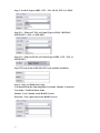
1
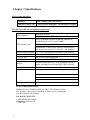
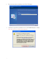
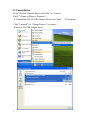
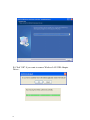
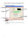
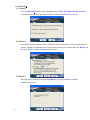
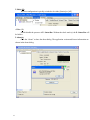
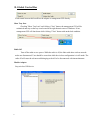
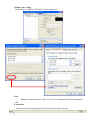
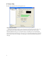
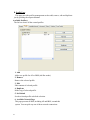
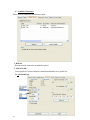
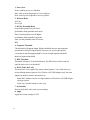
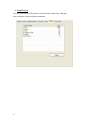
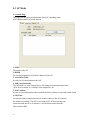
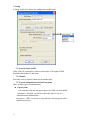
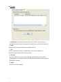
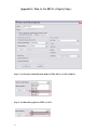
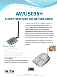
AWUS036H USB Adapter User Manual 1 V1.3 USING THIS DOCUMENT This document provides detailed user guidelines for AWUS036H USB Adapter operation and setting-up. Though every effort has been made to ensure that this document is up-to-date and accurate, more information may have become available subsequent to the production of this guide. Content Chapter 1 Introduction ................................................................................................3 Chapter 2 Specifications ..............................................................................................4 Chapter 3 Installation/ Uninstallation.........................................................................5 3.1 Installation............................................................................................................5 3.2 Uninstallation .......................................................................................................8 Chapter 4 RtWLAN: Wireless LAN Management GUI ...........................................12 4.1 Introduction of Main Window............................................................................12 4.2 Station Mode ........................................................................................................18 4.3 AP Mode ...............................................................................................................26 Appendix 1: How to Use 802.1x ( Step by Step )..........................................................32 2 Chapter 1 Introduction Thank you for purchasing AWUS036H USB Adapter. AWUS036H USB Adapter is a perfect combination of both performance and cost-effective product introduced. It is sincerely hoped that you can enjoy the wireless world through this solidly profiled wireless adapter. It provides a full solution of all the IEEE 802.11 b/g protocols, that pass the WiFi tests and are compatible with all the wireless products with WiFi logo. If you have a AWUS036H USB Adapter on hand, it means you can connect to the wireless world without any difficulty. It also provides all the data rates in the IEEE 802.11 b/g standards, with both short and long preambles to ensure the compatibility of legacy wireless products and new ones, saving the panic works for end users to find compatible products. Since the security issue has become one of the most important one in the wireless society, it provides you with the full security coverage from the 64/128bits WEP encryptions, second generation WPA-PSK encryption, to the most advanced WPA2-AES encryption. WPA2 is the latest security standard currently approved by WiFi standards. Saving mode, Adhoc wireless Lan, Wake on Lan (WOL) and other exciting features are also included in this AWUS036H USB Adapter. This user manual will guide you through these exciting features in the following chapters and we is believed that you will be greatly satisfied with its performance and ease of use. Notice : The changes or modifications not expressly approved by the party responsible for compliance could void the user’s authority to operate the equipment. IMPORTANT NOTE: To comply with the FCC RF exposure compliance requirements, no change to the antenna or the device is permitted. Any change to the antenna or the device could result in the device exceeding the RF exposure requirements and void user’s authority to operate the device. 3 Chapter 2 Specifications Host system connections Interface Fully complies with USB 2.0 or 1.1 USB date transfer rate USB high speed (480Mbps), and full speed (12Mbps) Wireless LAN (WLAN) environment connections WLAN Interface Multimode features Fully complies with IEEE 802.11 b/g specifications 802.11 b:DQPSK with data scrambling capability to provide data rate of 1,2,5.5 and 11Mbps WLAN transfer rate 802.11 g:A high-speed Fast Fourier Transform(FFT)/Inverse Fast Fourier Transform(IFFT) provide data rate of 6,9,12.18,24,36,48 and 54Mbps WLAN Frequency Band Operation Channel Coverage Area Compatibility 2.4 ~ 2.497 GHz ((Industrial Scientific Medical Band) Channel 1 ~ 11 Indoors:100ft with straight path Fully compatible to IEEE 802.11 b/g devices Security Hardware-based IEEE 802.11i encryption/decryption engine, including 64-bit/128-bit WEP, TKIP, and AES Antenna Detachable dipolar antenna SYSTEM REQUIREMENTS Windows System : Windows 98SE, Me, 2000, XP or Windows 64bit. PCs must have a device driver installed. It allows you to communicate with WLAN Mini USB Adapter. PACKAGE CONTENTS 1.AWUS036H USB Adapter 2.Installation Software CD 3.USB Cable 4 Chapter 3 Installation/ Uninstallation Warning! Do not cover or block the airflow to the adapter. The adapter will reach a high temperature during use. 3.1 Installation Before you proceed with the installation, please notice the following descriptions. Note1: The following installation was operated under (Proceduresare similar for Windows 98SE/Me/2000.) Windows XP. Note2: If you have installed the WLAN USB driver & utility before, please uninstall the old version first. 1. Do not plug the wireless LAN USB adapter into your computer USB port before installing the software program . Insert the software program CD , then auto installation window pops up on following: 2. 5 While the following screen pops out, click Driver Installation 3. Click Driver Installation 4. Choose a set up language. Click Next to process the installation. 6 5. 6. The system starts software installation of the WLAN USB adapter. On Windows Logo Software Installation screen, click Continue Anyway to continue. Note: Not all the drivers will have this message box. 7 7. Click Finish to complete the installation. 8. After click Finish to complete the installation , under Windows XP <ALL Programs> menu , REALTEK USB wireless LAN Utility program installed. 9. Insert the wireless LAN USB adapter into your computer USB port , the computer detected and active the wireless LAN USB adapter automatically. 8 3.2 Uninstallation From “Wireless Network Driver and Utility” or “Control Panel” ”Change or Remove Programs”. A. Uninstall the WLAN USB Adapter Driver from “Start” “All Programs” Click “Uninstall” (or “Change/Remove”) to remove Wireless LAN USB Adapter driver. 9 B. Click “OK” if you want to remove Wireless LAN USB Adapter Driver . 10 C. Click “Finish” to complete the uninstallation. 11 Chapter 4 Rt WLAN: Wireless LAN Management GUI 4.1 Introduction of Main Window A. Main Menu C. Properties Area B. Adapter List Area D. Global Control Bar E. Status Bar A. Main Menu The main menu includes five submenus. 1.Refresh(R) When clicking the refresh menu, you can update and re-enumerate the contents of adapter list area. 12 2.Set Wizard(S) 2.1 Wizard-1 Click Set Wizard(S) menu to enter operation wizard. Click AP: Setup a wireless network. To configure Access Point parameters. Next to continue. Cancel to leave wizard 2.2Wizard-2 User defines wireless network Name [SSID](less than 32 characters). User may skip wireless security. Strongly recommend user to setup wireless security to avoid invalid users. Back to go previous. Next to continue. Cancel to close wizard. 2.3Wizard-3 This page shows SSID & Security settings Back to go previous Next to continue. Cancel to close wizard. 13 2.4Wizard-4 Select device that connects with internet. Back to go previous. Next to continue. Cancel to close wizard. 2.5Wizard-5 Show all settings under AP mode. Click Finish to complete wizard setup. 14 3.Mode (M) Wireless configuration is quickly switched to be either [Station] or [AP]. 4.View (V) Enable/disable the presence of E. Status Bar. Without the check mark (v) the E. Status Bar will be hidden. 5.About(A) Click the “About” to show the about dialog. The application version and license information are shown in the about dialog. 15 B. Adapter List Area All connected adapters on this system with multiple adapter installations are displayed in this area. It is easy for users to change the selected adapter by one click. The contents of properties area are dependant on wireless configuration that the selected adapter is set up. If only single adapter is installed on the system, only one adapter is always selected. C. Properties Area The contents of this area are dependent on current wireless configuration. The current configuration is determined on previous explanation of submenu “Mode”. The more detailed contents are described in the following wireless configuration sections for both Station and AP mode. 16 D. Global Control Bar Each control item on this bar affects the adapter or management GUI directly. Show Tray Icon Checking "Show Tray Icon" and clicking “Close” button, the management GUI will be minimized and stay on the tray icon located at the right bottom corner of Windows. If not, management GUI will shut down while clicking "Close" button with unchecked condition. Radio Off Turn off the radio to save power. While the radio is off, the links with other wireless network nodes are disconnected. User should be aware that while the wireless configuration is in AP mode. The radio off will cause the sub network belonging to the AP to be disconnected with internet/intranet. Disable Adapter Stop wireless USB device. 17 Windows Zero Config Switch utility to Windows XP default wireless setting tool. Close Whether to check or uncheck "Show Tray Icon" is to shutdown or hide the management GUI. E. Status Bar The hints or status of the management GUI are presented in the status bar. 18 4.2 Station Mode The following explanations focus on the properties area. Infrastructure and Ad-Hoc With both Infrastructure and Ad-Hoc types, the properties should look like the picture above. Six property pages present different information of current wireless network status. Please read the following explanations before you reviewing these pages, it could help you to well understand the wireless environment around the system. It is easy to use to switch property pages just by clicking left button of mouse on the title of each page. The following six sections describe detailed information of each page. 19 A. General Page This page represents the general information of this adapter. 1. Status The status of station connection to AP. 2. Speed Current transition speed in Mbps 3. Type (Mega-Bits-Per-Second). Current wireless LAN configuration type. 4. Encryption Current encryption mode used. 5. SSID Name of wireless network. 6. Signal Strength The average signal quality of packets received from wireless network. We recommend connecting AP with over 70% signal strength. 7. Throughput Diagram Current throughput, including transmission (Tx) and total traffic (Total). 8. Network Address Mac Address: six two-digital number of this Wireless LAN USB adapter IP Address: assigned network address by DHCP server or ■ ■ 20 self-definition in four three-digital number format. Subnet Mask: the only valid value is 2555.255.255.0 Gateway: It comes from connected AP. Your system can not connect internet with this field empty. B. Profile Page This page provides profiles management such as add, remove, edit and duplicate just by pressing the respected button. Available Profile(s) The list box shows all the created profiles. 1. Add Add a new profile for AP or IBSS (Ad-Hoc mode). 2. Remove Remove the selected profile. 3. Edit Edit contents of selected profile. 4. Duplicate Make copy of selected profile. 5. Set Default Set the selected profile as default selection. 6. Available Network Page This page presents all BSS, including AP and IBSS, around this system. You can pick any one of these network connections. 21 C. Available Network(s) Show network connection around this system 1. Refresh Rescan network connection around this system. 2. Add to Profile Create profile for selected network connection and add it to to profile list. D. Advanced Page 22 1. Power Save None: without power save function. Min: wake up more frequently to receive packets. Max: wake up less frequently to receive packets. 2. Wireless Mode 802.11b 802.11g/b 3. 802.11b Preamble Mode Long: higher quality but with lower performance than preamble short mode. Short: Normal quality but with higher performance than preamble long mode. Auto: use the preamble mode of current. BSS. 4. Fragment Threshold The threshold of fragment length. Higher threshold increase data transition performance with good signal quality. However, in a poor signal quality environment, data throughput might be worse on high fragment threshold than low fragment threshold. 5. RTS Threshold Threshold of Request To Send mechanism. The RTS frame will not send out until the packet size over threshold. 6. WOL (Wake On LAN) The wake-on-LAN is applied for remote control purpose. You could wake up a system through network packets. For Wireless LAN USB Adapter, only the same adapter on another system could wake it up. Input MAC Address: the six two-digit numbers of Wireless LAN USB Adapter on target system. Wake Up: click this button to wake it up . 7. Set Defaults Restore the default value to be current settings. 8. Apply Apply the current settings to GUI. 23 E. Status Page NDIS Driver Version: Driver version Short Radio Header: No Encryption: Current encryption mode. Authenticate: Authentication state Channel Set: Selected channel plan currently. MAC Address: MAC address of this adapter. Data Rate: Wireless LAN transition speed Channel(Frequency): Current channel number Status: Wireless network status SSID: name of connecting AP Network Type: Indicate current network configuration type Power Save Mode: Current setting power save mode Associated AP MAC: MAC address of connecting AP Associated AP IP: IP address of connecting AP Up Time: Total connection time 24 F. Statistics Page You could watch the Tx/Rx status of current wireless connection. This page shows a statistic analysis of packet transition. 25 4.3 AP Mode A. General Page This page provides general information of this AP, including name, MAC address and list of joined stations. 1. SSID The name of this AP. 2. BSSID Six two-digital numbers of the MAC address of this AP. 3. Association Table It is the list of joined stations to this AP. 4. AID (Association ID) The AID field is a value assigned by an AP during association that represents 16-bit ID of a station. It is a unique value assigned by AP. 5. MAC address It is the six two-digit numbers that assemble the MAC address of respected joined station. 6. Life Time It is the timer that counts down from 10 minutes whenever the AP connects the station successfully. If an STA associated to SW AP does not have any interaction with the AP in 10 minutes, it will be disassociated from the Infra-structure BSS. 26 7. Config A dialog of this AP is shown for configuration modification. 7.1. Network Name (SSID) Name of the AP searchable by other wireless nodes. The length of SSID should be shorter than 32 characters. 7.2. Channel Select the wireless channel within current channel plan. 7.3. Network Authentication & Data Encryption There are three types of authentication: ■ Open System It is combined with data encryption type to be WEP or to be disabled. Encryption ~ disabled: you decide to open this AP to every one without network authentication. Encryption ~ WEP: you decide to setup the basic data encryption with a defined network key. 27 ■ Shared Key + WEP You decide to apply both authentication and data encryption to prevent unauthouized login. WPA-PSK + TKIP & WPA2-PSK + TKIP ■ The most advanced authentication and data encryption that provide the best security protection. 7.4. ASCII/ PASSPHRASE The most advanced authentication and data encryption that provide the best security protection. ■ ASCII: You should provide either 5 or 13 ASCII characters on Network key edit box. ■ PASSPHRASE: You could input words on Network Key edit box. 64 bits: The generated pass key is 64-bit to be complied with data packets. 128 bits: The generated pass key is 128-bit to be ■ complied with data packets. Hexadecimal: While both ASCII and PASSPHRASE are not checked, you should input hexadecimal number in the network key box. For example, 10 digits hex number for 64-bit WEP or 26 digits hex number for 128-bit WEP. 7.5. Key index (1 ~4) At most four key index to represent the opposite network key. 28 B. Advanced Page Users could setup the advanced characteristics of network packet for transmission on this page. 1. Beacon Interval This filed indicates the interval between each beacon that this AP sends out in unit of TU (1024 micro-seconds). 2. DTIM Period The DTIM Period field is the number of Beacon intervals between successive DTIMs. 3. Preamble Mode ■ Long: higher quality but with lower performance than preamble short mode. ■ Short: Normal quality but with higher performance then preamble long mode. ■ 29 Auto: select the proper preamble mode by current signal frame information. C. Statistics Page The Tx/Rx status of current wireless connection is shown. A statistic analysis of packet transition is listed. 30 D. ICS Page 1. ConnName List all network connections to this system. You can pick up one from the listed item(s) whose network domain you would want to connect to. 2. Select Make the desired network connection to public network. 3. ICS Internet Connection Sharing. It enables this AP to create the domain to share this internet/intranet network connection 4. Firewall Any of a number of security schemes that prevents unauthorized users from gaining access to a computer network, or that monitors transfers of information to and from the network. 5. Apply Execute the current settings. 31 Appendix 1: How to Use 802.1x ( Step by Step ) Step 1 : Set Network Authentication mode to WPA 802.1x ,or WPA2 802.1x Step 2 : Set Data Encryption to TKIP ,or AES 32 Step 3 : Set EAP Type to MD5 , GTC , TLS , LEAP , TTLS ,or PEAP Step 3.1.1 : When set TTLS, set Tunnel Type to CHAP , MSCHAP , MSCHAP-V2 , PAP , or EAP-MD5 Step 3.1.2 : When set PEAP, set Tunnel Type to MD5 , GTC , TLS , or MSCHAP-V2 Step 3.2 If you do not set PEAP to TLS ,you could use certificate. Step 4 : After you finish above steps. You should fill up the following fields( Username , Identity , Password ). User name : Certificated user name . Identity : User's identity on the RADIUS server Password : User's password on the RADIUS server 33 FCC INFORMATION The Federal Communication Commission Radio Frequency Interference Statement includes the following paragraph: The equipment has been tested and found to comply with the limits for a Class B Digital Device, pursuant to part 15 of the FCC Rules. These limits are designed to provide reasonable protection against harmful interference in a residential installation. This equipment generates, uses and can radiate radio frequency energy and, if not installed and used in accordance with the instruction, may cause harmful interference to radio communication. However, there is no grantee that interference will not occur in a particular installation. If this equipment dose cause harmful interference to radio or television reception, which can be determined by turning the equipment off and on , the user is encouraged to try to correct the interference by one or more of the following measures: --Reorient or relocate the receiving antenna. --Increase the separation between the equipment and receiver. --Connect the equipment into an outlet on a circuit different from that to which the receiver is connected. --Consult the dealer or an experienced radio/TV technician for help. The user should not modify or change this equipment without written approval Form loopcomm technology. Modification could void authority to use this equipment.