1
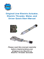
Original Line Electric Actuator,
Electric Thruster, Motor, and
Driver Quick Start Manual
Please read this manual carefully
before implementing your
Original Line Electric or
Electric Thruster Actuator
Scope of this manual
This instruction manual supports Bimba standard
components only. If special motion control components, including but not limited to power supplies,
encoders, motors, controls, and drivers, are included
based on a customer’s specifications or special
request, it is the customer’s responsibility to consult
support materials and technical support specific to
these special components provided by the third party
manufacturers. Bimba assumes no liability for misuse,
misapplication, or support for components that are not
the Bimba brand.
Original Line Electric Actuator,
Electric Thruster, Motor, and
Driver Quick Start Manual
Contents
1. Actuator-only Models ...................................................................... 2
Installing your motor
2. Actuator and Motor Models ............................................................ 4
Motor specifications and wiring diagram
3. Actuator, Motor, and Driver Models ................................................ 6
a. Mount your drive ...................................................................... 6
b. Connect the DC power supply to the driver ............................. 7
c. Connect the motor to the driver ............................................... 7
d. Set rotary switch for motor selected ........................................ 8
e. Adjust running and idle current ................................................ 8
f. Set load inertia ........................................................................ 9
g. Select step resolution .............................................................. 9
h. Apply power and run self test ................................................ 10
i. Connect input signals ............................................................ 10.
j. FAULT output ......................................................................... 13
k. Set step pulse type ................................................................ 14
l. Step pulse noise filter ............................................................ 14
m.Technical specifications ......................................................... 15
n. Alarm codes .......................................................................... 16
Troubleshooting Guide and FAQ ...................................................... 17
1
Congratulations on purchasing an Original Line Electric actuator from
Bimba. Our OLE and OLET actuators are designed, built, and tested to
provide the longest life, greatest durability, highest speed, and greatest
thrust per dollar. We look forward to serving your electric actuator needs
with the same responsiveness and engineering expertise you are accustomed to receiving for our pneumatic products.
Every OLE and OLET actuator is backed by a one-year warranty. Extend
it to a two-year warranty by registering on our website at
www.bimba.com/pdf/OLEwarrantyregistration.pdf.
1. Actuator-only Models
Installing your motor
a. Remove plug to provide access to
coupler. Use a 1/8 inch allen key.
b. Turn the actuator coupler so the clamp screw is aligned with the
access hole. Loosen coupler setscrew using allen key. Allen key
sizes are identified in Table 1.
!
Only loosen the clamp screw until it no longer secures the
motor shaft. Loosening it too much may result in the screw
falling out of the coupler, or binding against the actuator’s
inside wall.
Table 1
Allen Key
5/64"
3/32"
3/32"
Note: Torque range is ± 10%.
Actuator
75
150
350
Torque
3.8 in-lbs.
8 in-ibs.
8 in-lbs.
2
c. Mount motor to actuator, slip shaft into coupler. Secure motor to
actuator using 4 screws provided. Allen key sizes and torque values are provided in Table 2. Be careful not to turn the coupler.
Table 2
Allen Key
9/64"
9/64"
5/32"
Note: Torque range is ± 10%.
Actuator
75
150
350
Torque
12 in-lbs.
12 in-lbs.
35 in-lbs.
d. Tighten coupler clamp screw so motor shaft is secured (refer to
Table 1 for torque specification). The coupler clamps around the
circumference of the motor shaft. The orientation of any flat (or key-
way) on the shaft does not matter.
!
Tighten the coupler clamp screw to the torque value in Table 1.
e. Replace the coupler access plug.
!
DO NOT screw the plug in to a hard stop. Only screw it in far
enough so that the top of the plug is flush with the outside
surface of the actuator.
3
$
2. Actuator and
Motor Models
Orange
All Bimba step Org/Wht
motors use the same 6HULHV
8-wire wiring color
code convention,
as Blk/Wht
shown below. .
$²
Black
Red
Red/
Wht
%
!
Yel/
Wht
$
Blk/Wht
Org/
Wht
$²
Yellow
%²
Orange
3DUDOOHO
Black
Red
Yel/
% Wht
Figure 1
Yellow
Red/Wht
%²
Warning: Be sure power is off before connecting or disconnecting the motor.
Specifications for Bimba 8-lead 1.8 degree step motors are provided in
Table 3.
Winding Min. Holding
Frame
Connection Torque (oz-in)
Parallel
62.3
Series
62.3
17
Unipolar
43.9
Parallel
177
23
Series
177
Unipolar
125
Parallel
269.1
23
Series
269.1
Unipolar
191.2
Parallel
1260
34
Series
1260
Unipolar
906
Table 3
Volts
2.9
5.6
4.0
2.1
4.2
3.0
2.1
4.2
3.0
2.72
5.43
3.88
Amps Ohms
1.7
0.85
1.2
4.2
2.1
3.0
4.2
2.1
3.0
5.6
2.8
4.0
1.7
6.6
3.3
0.37
1.5
0.75
0.5
2.0
1.0
0.48
1.94
0.97
mH
2.5
10.0
2.5
1.2
4.8
1.2
1.7
6.8
1.7
5.4
21.6
5.4
Rotor Inertia
(oz-in2/g-cm2)
0.44/82
0.44/82
0.44/82
1.64/300
1.64/300
1.64/300
2.51/460
2.51/460
2.51/460
15.0/2750
15.0/2750
15.0/2750
If you have ordered your actuator with a motor/encoder combination, the
encoder specifications are listed in Table 4.
Table 4
Incremental Encoder Specifications
Power Input
5 V DC, 160 mA
Resolution
2000 pulses per rev.
Output High
2.5 V DC Min.
Output Low
0.5 V DC Max.
Operating Frequency
500 kHz Max.
Operating Temperature
-30 to 115°C
Enclosure Rating
IP40
4
Encoder connections for Bimba step motors are identified in Table 5.
The cable provided has flying leads which can be connected to your
controller.
Pin No.
1
2
3
4
5
6
7
8
9
10
11
12
13
14
15
Table 5
Wire Color
Yellow
Yellow/White
Blue
Blue/White
Orange
Orange/White
Green
Green/White
Brown
Brown/White
White
Gray/White
Red
Black
Gray
5
Function
Channel A
Channel AChannel B
Channel BIndex
Index-
Not used
+5 V DC input power
Encoder ground
Drain/shield
3. Actuator, Motor, and Driver Models
You will need:
• An OLE or OLET actuator with motor attached.
• A small flat blade screwdriver for tightening the connectors.
• Wires - 18 to 20 gage recommended
• Wire cutter/stripper
• An appropriate DC power supply.
!
Warning: Do not apply power until all connections are made.
The DRV-4 accepts power supply voltages from 24 to 48 VDC, while the
DRV-8 accepts power supply voltages from 24 to 75 VDC. The current
demand will never exceed double the motor current (see Table 3, Amps
column). However, the DRV will convert a high voltage low current power
supply into a lower voltage higher current power supply. A 24V 4A supply will
perform similarly to a 48V 2A supply. Use Table 7 below as a guideline.
!
Use unregulated power supplies without overvoltage protection
to avoid problems with regeneration during rapid deceleration.
OLE
Drive
-75
-75
-150
-350
DRV-4
DRV-4
DRV-8
DRV-8
Power
Supply
Voltage
24-48
24-48
24-75
24-75
Bimba
Motor
17 frame
23 frame
23 frame
34 frame
Table 7
Parallel Parallel 24V Power 48V Power
Max
Current Current
Supply
Supply Amps per
Draw Draw Max. Amperage Amperage Phase
1.7
3.4
4
2
4.5
4.0
4.5
4
2
4.5
4.2
8.4
8
4
7.8
5.6
11.2
12
6
7.8
a. Mount your drive
Motor & Power Supply
Connector
Mount the drive using #6 screws.
Installing on a metal surface
(recommended) helps dissipate heat.
Forced air flow from a fan is also
good practice.
Run Current, Idle Current
Steps/rev, Inertia, Self Test
6
Input & Output
Signals
Motor Selector
Status LEDs
!
Warnings:
• Do not install drive where ambient air is more than 104° F.
• Do not install drive where there is no air flow
• Do not install drive where drive can get wet.
• Do not install drive where electrically conductive material can
fall on the driver.
• Drives must be mounted at least one-half inch apart.
b. Connect the DC power supply to the driver -- Do not
apply power
!
Warning: Observe proper polarity when connecting wires.
I. Make sure the power supply is not on. Connect V+ and V- from the power supply to the V+ and V- terminals of your driver.
II. Ensure a proper earth ground connection by
using the screw on the left side of the chassis.
All system components must be grounded to
a single point common earth ground.
If using an external fuse, we recommend the
following in-line with the V+ connection:
DRV-4: 3AG, 4 amp (Littlefuse 313004P)
DRV-8: 3AG, 6.25 amp (Littlefuse 3136.25P)
c. Connect the motor to the driver
!
Warning: Never connect or disconnect the motor when power is
applied.
Connect OLE or OLET eight lead motors in parallel, as shown below. If using a motor from another source, please refer to your motor specs for wiring
information. A motor wiring diagram is shown in Figure 1.
A+ A- B+ B-
ht
/w ht
w
t
+ rg/ ht
e
wh
g
o
an k+ l/w d/
or lac ye +re
b ed+ ow
r ell
y
k
bl
7
d. Set rotary switch for the motor selected
(This is normally set by the factory for the motor specified.)
Turn the rotary switch to the number that represents
the motor you have. This sets current and antiresonance settings for optimum performance.
OLE
-75
-75
-150
-350
Bimba Motor
Frame
17 frame
23 frame
23 frame
34 frame
Option Code
Setting
P1, E1, Y1, Z1
P2, E2, Y2, Z2
P2, E2, Y2, Z2
P3, E3, Y3, Z3
5
7
6
F
e. Adjust running and idle current
Switch 1 and 2 set the running
current to 70%, 80%, 90%
or 100% of the motor’s
rated maximum current.
Switch 4 sets the idle current
to either 50% or 90% of the
selected running current.
Factory default is 90%.
1 2
1 2
1 2
1 2
4
4
100%
90%
80%
70%
50%
90%
• Use 100% position in most applications (factory default)
!
• Use lower settings for self locking threads (OLE 12, 16, and
20 leads).
• Use lower settings to reduce
motor temperature
• Use higher settings for full holding torque
• Use lower setting during
initial setup to avert
accidental damage
• Use lower settings to address
safety issues
• Use lower settings to reduce
motor temperature
8
f. Set load inertia
Switch 3 chooses between
two load inertia ranges.
• Values are multiples of rotor
inerta (see Table 3)
• Use 0-4x for smaller (0.2" or
smaller) leads and shorter
strokes (factory default)
• Use 5-10x for longer (0.25" or
larger) leads and greater loads
• 5-10x may reduce performance.
This information is used in the
anti-resonance configuration.
3
3
5-10X
0-4X
g. Select step resolution
There are 4 microstep resolutions to choose from as well as full and half
step
•200
•200µ (microstep emulation)
factory default
•400
5 6 7
5 6 7
5 6 7
5 6 7
20000
12800
5000
2000
5 6 7
5 6 7
5 6 7
5 6 7
400 µ
SMOOTH
400
200 µ
SMOOTH
200
•400µ (microstep emulation)
•2000
•5000
•12800
•20000
The 200µ and 400µ settings use microstep emulation to provide smooth
rotation at low speeds. Microstep emulation imparts a slight delay to the
motion. If this is not acceptable, use the non-filtered 200 or 400 settings.
9
Microstepping provides smoothest rotation. However, a faster step pulse
rate (frequency) is required for a given RPM as shown in Table 8 below.
Pulses per Degrees per
revolution
step
200
1.8
400
0.9
2000
0.18
5000
0.072
12800
0.028
20000
0.018
Table 8
Pulse frequency required for 300 RPM
1,000 Hz
2,000 Hz
10,000 Hz
25,000 Hz
64,000 Hz
100,000 Hz
Pulse frequency required for 3000 RPM
10,000 Hz
20,000 Hz
100,000 Hz
250,000 Hz
640,000 Hz
1,000,000 Hz
h. Apply power and run self test
The DRV-4 and DRV-8 have built in Self Test functions.
When switch 8 is moved to the ON position, the
drive will automatically rotate the motor back and
forth, two turns in each direction. This feature can
be used to confirm that the motor is correctly wired,
selected and operational. Factory default is “OFF.”
8
8
ON OFF
SELF TEST
i. Connect input signals
The drives have three inputs:
• STEP: a high speed digital input for step pulse commands, 5-24 volt logic
• DIR: a high speed digital input for the direction signal, 5-24 volt logic
• EN: a 5-24V input for commanding the removal of power from the motor
STEP and DIR inputs can be converted to STEP CW and STEP CCW by
moving the internal jumper S3. For detailed instructions, go to Step “K” of
this section.
Refer to the illustration below for identification of step, direction, and
enable inputs on the driver screw terminal blocks.
FAULT–
FAULT+
EN–
EN+
DIR–
DIR+
STEP–
STEP+
Motor & Power Supply
Connector
Input & Output
Signals
inside drive
Status LEDs
STEP+
220 pF
STEPDIR+
220 pF
DIRRun Current, Idle Current
Steps/rev, Inertia, Self Test
Motor Selector
10
Connection Examples: STEP & DIR
Indexer
with
Sourcing
Outputs
COM
DIR-
DIR
DIR+
STEP-
STEP
DRV
STR
STEP+
Connecting to indexer with Sourcing Outputs
Indexer
with
Sinking
Outputs
+5V OUT
DIR+
DIR
DIRSTEP+
STEP
STR
DRV
STEP-
Connecting to Indexer with Sinking Outputs
Indexer
with
Differential
Outputs
DIR+
DIR+
DIR-
DIR-
STEP+
STEP+
STEP-
STEP-
STR
DRV
Connecting to Indexer with Differential Outputs
(Many High Speed Indexers have Differential Outputs)
11
Connection Examples: EN
The 5-24 V EN input disables power to the motor.
5-24
VDC
Power
Supply
EN+
+
STR
DRV
switch or relay
(closed=logic low)
-
EN-
Connecting an Input to a Switch or Relay
Si drive
EN+
OUT+
EN-
5-24
VDC
Power
Supply
STR
DRV
DRIVE
+
-
OUT–
Connecting another drive to EN
(When output closes, input closes)
12-24
VDC
Power
Supply
+
-
+
output
NPN
Proximity
Sensor
–
EN+
EN-
DRV
STR
Connecting an NPN Type Proximity Sensor to an input
(When prox sensor activates, input closes)
12-24
VDC
Power
Supply
+
+
output
PNP
Proximity
Sensor
–
EN+
EN-
-
STR
DRV
Connecting a PNP Type Proximity Sensor to an input
(When prox sensor activates, input closes)
12
j. FAULT output
The DRV drives feature a digital FAULT output. This output closes to signal a
fault condition.
This output can be used to drive LEDs, relays and the inputs of other electronic devices like PLCs. The “+” (collector) and “-” (emitter) terminals of the
output transistor are available at the connector. This allows you to configure
the output for current sourcing or sinking. Diagrams of each type of connection follow.
!
Do not connect the output to more than 30 VDC.
The current through the output terminal must not exceed 80 mA.
5-24 VDC
Power Supply
+
FAULT+
STR
DRV
5-24 VDC
Power Supply
–
STR
DRV
Load
+
–
FAULT+
COM
FAULT-
IN
FAULT-
Sinking Output
Sourcing Output
relay
5-24 VDC
Power Supply
+
FAULT+
DRV
STR
1N4935 suppression diode
FAULT-
Driving a Relay
13
–
PLC
k. Set step pulse type
Most indexers and motion controllers provide motion commands in the “Step
and Direction” format. The Step signal pulses once for each motor step and
the direction signal commands direction. However, a few PLCs use a different type of command signal: one signal pulses once for each desired step in
the clockwise direction (called STEP CW), while a second signal pulses for
counterclockwise motion (STEP CCW). The drives can accept this type of
signal if you remove the cover and move jumper S3 from the “1-2” position to
the “1-3” position. Factory default is the 1-2 position. As you can see in the
image, the jumper terminals (2, 1, 3) and S3 and S4 designators are printed
in white on the circuit board.
Jumper S4: noise filter
Shown in 1-2 position
Jumper S3: step pulse type
Shown in 1-2 position
l. Step pulse noise filter
Electrical noise can cause the drive to think that one step pulse is two or
more pulses, resulting in extra motion and inaccurate motor and load positioning. To combat this problem, the drive includes a digital noise filter on the
STEP and DIR inputs. The default factory setting of this filter is 150 kHz.
If you are operating the drive at high speeds with step rates above 150 kHz,
remove the cover and move jumper S4 from the 150 kHz position (1-3) to the
2 MHz position (1-2) as shown below.
Your maximum pulse rate will be the highest motor speed times the steps/
rev. For example, 40 revs/second at 20,000 steps/rev is 40 x 20,000 = 800
kHz. Please consider this when deciding if you must increase the filter frequency.
14
m. Technical specifications
Amplifier
Digital MOSFET. 20 kHz PWM. Suitable for driving two
phase and four phase step motors with four, six or eight
leads.
Supply voltage:
DRV-4
24-48 VDC
Under voltage alarm: 20 VDC
Over voltage shutdown: 60 VDC
DRV-8
24-75 VDC
Under voltage alarm: 20 VDC
Over voltage shutdown: 85 VDC
Motor current:
0.5 to 7.8 amps/phase peak of sine (DRV8)
0.25 to 4.5 amps/phase peak of sine (DRV4)
Digital Inputs Optically isolated, 5 - 24V logic. Sourcing, sinking or
differential signals can be used.
Minimum “on” voltage: 4 VDC.
Maximum voltage: 30 VDC.
Input current: 5 mA typ at 4V, 15 mA typ at 30V.
Fault Output
Physical
Photodarlington, 80 mA, 30 VDC max. Voltage drop: 1.2V
max at 80 mA.
1.3 x 3.0 x 4.65 inches (33 x 75.5 x 118 mm) overall. 10.8
oz (305 g) including mating connectors.
Ambient temperature range: 0° C to 40° C.
Mating Connectors
Motor/power supply: PCD P/N ELV06100 (Phoenix Contact 1757051),
included with drive.
Signals: PCD P/N ELVH08100 (Phoenix Contact 1803633), included with
drive.
15
n. Alarm codes
In the event of a drive fault or alarm, the green LED will flash one or two
times, followed by a series of red flashes. The pattern repeats until the alarm
is cleared. You may clear the alarm by cycling power off and then on.
Code
Error
Action Required
solid green
no alarm, motor
disabled
open enable input
G G
flashing green
no alarm, motor
enabled
none
R R
flashing red
configuration or
memory error
repair
G R R R R
1 green, 4 red
power supply
voltage too high
reduce power
supply voltage
G R R R R R
1 green, 5 red
over current/short
current
check motor
connections
G R R R R R R
1 green, 6 red
open motor winding
check motor
connections
G G R R R
2 green, 3 red
internal voltage out
of range
repair
G G R R R R
2 green, 4 red
power supply
voltage too low
increase power
supply voltage
G
16
Troubleshooting Guide and FAQ
Problem: Actuator does not move when step motor is energized.
Solution: Step motor windings may be shorted. Use an Ohmmeter to
measure the resistance between pairs of windings (should be infinite)
and between the leads of each winding (should be the same for each
winding). Use your motor’s wiring diagram to identify the correct leads.
If windings are shorted, the motor must be replaced.
Problem: Actuator operation is stiff, seems to be binding.
Solution: Check for dents on the body tube, motor end bell, and damage to the square rod. If there are signs of visible damage, the actuator
or motor or both may need to be replaced. Dents on the motor shaft or
endbells may cause the rotor to seize or rub, producing binding and stiff
operation. While the nut of the OLE actuator is self-lubricating, rod lubrications is recommended at regular intervals. Use Bimba HT-99 grease.
Problem: Can I use switches with my OLE for end of stroke sensing?
Solution: All OLE actuators have magnetic pistons. OLE actuators can
use the same switches as Original Line pneumatic cylinders. Refer to the
Bimba catalog for switch recommendations.
Problem: The motor gets hot.
Solution: Step motors tend to run hot (the actual maximum case temperature is 80° C). However, the motor should not get too hot to touch.
If it is overheating, the drive current may be set too high. All standard
OLE step motors are 8-wire motors. Refer to Table 3 in this manual for
required drive current levels. Also consider duty cycle; reduce either the
running current, idle current, or duty cycle. Instructions for adjusting idle
and running current are provided in section 3.e.
Problem: The motor is not producing enough torque or it stalls at low
speeds.
Solution: If the motor previously ran well, check the resistance of the
windings. Use an Ohmmeter to measure the resistance between different windings (should be infinite) and between the leads of each winding
(should be the same for each winding). Use your motor’s wiring diagram
to identify the correct leads. If windings are shorted, the motor must be
replaced.
If lack of torque is observed at the initial start up with a load and desired
speeds are not reached, check connections between the motor and drive
and check drive settings.
17
Inspect the motor and rotate the shaft when the motor is not connected.
If you feel any rubbing or there are any dents on the motor, there is probably an alignment problem and the motor may need to be replaced.
If the rotor was removed from the stator, it could have been demagnetized. The motor would need to be replaced.
If you still cannot solve the problem, the size of your power supply (voltage output) may need to be greater. When a step motor rotates, it acts
like a generator pumping voltage (back EMF) back into the drive. Back
EMF rises as motor speed and inductance increase and can cause a
stall. The solution is to either change from a series to a parallel connection (series connections quadruple inductance) or use a power supply
with a higher output voltage.
Problem: The motor doesn’t produce any holding torque.
Solution: Make sure that line power is on, the drive is powered up, and
the motor phases are connected correctly to the drive.
Problem: The motor (actuator) oscillates back and forth at low speeds.
Solution: This is due to resonance, common between 1-4 rps. If this is
observed with no load, add a load to the motor (the load will dampen out
resonance). Changing from full-step to half-step or microstepping will
also solve resonance problems.
Step and Direction Drives
Note: Please read your manual first before and during your setup. Bimba
manuals, available at www.bimba.com/OLE/manuals, are short, to the
point, and comprehensive.
Problem: The drive’s power LED does not illuminate when power is applied.
Solution: Check the fuse and replace if necessary with one of the extra
fuses included with your drive. If you have no fuses or continuously blow
fuses, call Bimba Technical Support. Check your power supply to be sure
it is not providing an excessively high voltage to the drive.
Problem: The motor runs then suddenly dies. The connections are correct.
Solution: Turn off power. Refer to your motor wiring diagram. Disconnect the motor. Using an ohmmeter, measure the resistance between the
A+ and A- and B+ and B- terminals. The reading should be in the megaOhms. If resistance is low, the H-bridge is damaged and the drive must
be returned on a RGA (Returned Good Authorization). If the resistance is
normal, inspect the board for any visible damage to the components and
check the motor for a short circuit in the windings.
18
Problem: The motor does not move when a step signal is sent to the
drive.
Solution: If the enable input is on (low with respect to a 5-24 volt signal),
it will disable the motor. Do not connect anything to the enable input if
there is no reason to disable the motor.
Problem: The motor will not run slow enough with a potentiometer connected to my drive (it has an internal oscillator).
Solution: Some drives’ internal potentiometers cannot be adjusted to
zero speed. Check the specifications in the manual that came with the
drive.
Problem: At startup, the motor does not run although the wiring is
correct.
Solution: Make sure that dip switches and jumpers are set properly.
Read your driver manual carefully.
Problem: System not working properly.
Solution: Troubleshoot by replacing the drive and see if the problem
persists. Please read your drive manual before and during your setup.
Bimba manuals, concise and comprehensive, are available for download
at our website, www.bimba.com.
19
Bimba Manufacturing Company
Monee, Illinois 60449-0068
Tel: 708.534.8544
Tech Support: 800.44BIMBA
Fax: 708.235.2014
[email protected]
www.bimba.com
OLE-513 Manual
D-110340
Effective May 2013