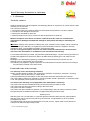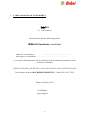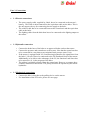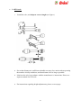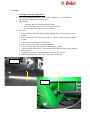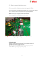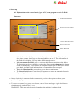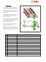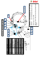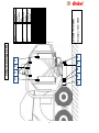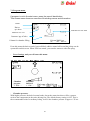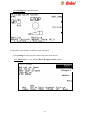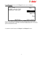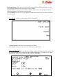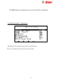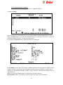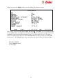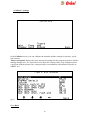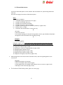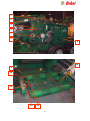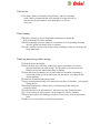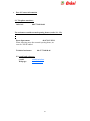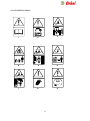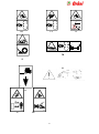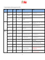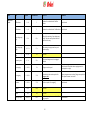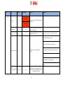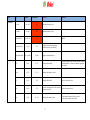
1
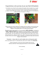
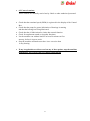
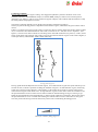
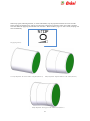
User`s Manual Orkel hiQ Smartbaler Round baler Year of manufacture: 2011 Manufactured by: Serial number, Round baler: ................................................. Orkel AS 7320 Fannrem Serial number, Wrapper: …………………………….. -1- Congratulations on the purchase of your new Orkel hiQ Smartbaler Our machines are renowned for their quality and strength, and are designed for use in tough environments. This is the result of continuous product development and thorough quality control prior to shipping the machinery. We have conducted an assessment procedure in accordance with the Norwegian machinery directive (DECLARATION OF CONFORMITY) and the machine is CE-labeled accordingly. Plates stating the serial numbers are located at the front (baler) and on the left main frame (wrapper). Serial numbers must always be at hand when contacting the supplier to order spare parts or for other technical support. Being the owner of the machine, you must read this USER`s MANUAL, including the SAFETY INSTRUCTIONS before starting to use the equipment, or before servicing the baler. Read the User Guide carefully and get familiar with the requirements for machine safety, use and maintenance, and make daily service a part of your routine. Check that this User`s Manual matches your baler. We require that the instructions in this User Guide are followed in order to maintain your personal safety and ensure the lifespan of the machine. Remember – always state the serial number when ordering spare parts! (This User Manual refers to combined balers with serial numbers from #20319001…. Certain information in this User Guide is labeled with this sign and/or by bold text. Please pay special attention to this information! Yours sincerely, Orkel AS -2- Table of contents: Part 1 Part 2 Part 3 Part 4 Part 5 Part 6 Part 7 Introduction 1.1 General 1.2 Safety 5 5 Warranty. Declaration of conformity 2.1 Warranty. 2.2 Declaration of conformity 6 8 Connections 3.1 Electric 3.2 Hydraulic 3.3 Mechanic 9 9 10 Settings 4.1 Height adjustment 4.2 Program settings 4.3 Mechanical settings 4.4 Hydraulic settings 11 12 12 Preparations prior to driving 5.1 Installing the wide film or net roller. 5.2 Installing the wrapper film roller.. 5.3 Adding grease to the lubrication system 5.4 Adding oil to the chain lubrication system 5.5 Ensiling fluid. 13 14 15 15 15 Start-up. 6.1 Explanations to the control unit. 6.2 Control routines. 6.3 Driving 6.4 Blocking in pick-up/ feeder unit 16 17 18 20 Technical information. 7.1 Electric system 7.2 Hydraulic system 7.3 Chamber pressure 7.4 Grass cutting system 7.5 HiT (wide film) system 7.6 Lubrication 7.7 Drive chains 7.8 Sensor scheme, baler 7.9 Sensor scheme, wrapper 7.10 Program menus 7.11Explanations to menu “Baling programs” 7.12Program menus, continued 7.13Overlap. How to adjust. 21 21 21 22 23 24 25 26 27 28 36 37 38 -3- Part 8 Part 9 Part 10 Maintenance 8.1 Daily maintenance. 8.2 Manual lubrication. 8.3 Service. 8.4 Cleaning. 8.5 Long time storage. 45 46 48 48 48 Contact 9.1 Vital phone numbers. 9.2 e-mail and webpage. 49 49 Important safety instructions 10.1 Introduction. 10.2 General safety instructions. 10.3 Connecting and disconnecting. 10.4 Adjustments 10.5 Maintenance and service 10.6 Lifting 10.7 Use 10.8 Transport 10.9 Parking 10.10 Dismantling 10.11 Warning signs/ labels. 10.12 Warning signs. Explanations. 51 52 53 54 54 55 55 55 55 55 56 58 Part 11 11.1 Settings for Danfoss versions from 5.4Pd6 -4- Part 1. • Introduction 1.1. General o This hiQ Smartbaler is meant for baling grass, straw and hay, and for these purposes only. o The bales will have a diameter of 1220 mm or more, and a width of 1220 mm. o The bales might weigh 1000 kg or more. o The hiQ Smartbaler has to be used accordingly to the instructions given in this manual. o If you are in doubt regarding the range of use of the machine, contact Orkel, or your local Orkel representative. • 1.2. Safety o Before using the machine, or doing any kind of work on the machine, the “important safety instructions” section, pages 40 – 47 has to be read and understood. o Fire hazard! Especially when baling dry material like dry grass, hay or straw, extra care has to be taken. Under these conditions a fire extinguisher should always be at hand. Even more hazardous is dry material mixed with oil. -5- Part 2 Warranty. Declaration of conformity. • 2.1 Warranty Terms for end user: Orkel AS warrants this machine against manufacturing defects for a period of 12 months from the date of delivery to the end user. The warranty is limited to: 1. The present value of the machine based on the maintenance performed, use and condition. 2. The value of the damaged components. 3. Work hours calculated by Orkel AS. 4. Warranty repairs must only be carried out with the permission of Orkel AS. With the exception of the above conditions, Orkel AS shall be, under no circumstances, responsible for damage/circumstantial damage to third parties that may be caused by the machine. Important: Ordinary wear and tear to rubber parts, tyres, hydraulic hoses, blades, chains or bearings is not covered by the warranty. As regards the power transmission shaft, the supplier’s warranty regulations apply - see separate information concerning the shaft. The use of non-genuine parts, incorrect use and/or insufficient maintenance of the machine will lead to the cancellation or invalidation of the aforementioned warranty. For machines with factory-mounted, fully automatic greased bearings, a 5-year warranty (maximum of 50,000 bales) applies from the delivery date to all slide bearings (bushing) for rolls, based on the following: Breakage to the slide bearing (bushing) is defined as material thickness of less than 0.2 mm. Working hours for replacement are not included. This warranty only applies if regular inspections and maintenance have been carried out according to the instructions outlined in this User Guide. Extent and terms of the warranty: The warranty covers the following situations: Repair of faults caused by faults in the construction, materials, components, production, mounting, alterations made by the factory or similar faults. Faults and defects discovered before or after the product has been delivered to the customer. The product will be replaced or repaired as soon as possible, should a production or construction fault occur, that potentially could represent a safety risk. The terms of the warranty are not applicable if the defect/fault is caused by: The product has not been handled according to the instructions provided by Orkel. The product has not been serviced according to the instructions. The product has been modified, The product has been installed or repaired, not corresponding to the instructions provided by Orkel. Non-genuine parts or standard components, not approved by Orkel, has been used. Warranty work Warranty work can only start after on a specific agreement with the Orkel warranty representative. Warranty work can be carried out by either by the customer, an Orkel dealer or other workshop pre-approved by Orkel If troubleshooting and repairs are estimated to more than 3 hours, repairs must not be carried out until the work has been approved by Orkel. To be continued next page. 6 Documentation Orkel’s warranty claim form must be used when contacting Orkel for any type of warranty repairs. This form is found at Orkel’s website www.orkel.no or can be sent by Orkel via email or regular mail, on request. The claim form must include information on: Product type, serial number, purchase date, and the date when the problem occurred. A description of the fault, and necessary actions to be taken. Parts, including the number of parts used and their part numbers, if such parts are used. Reference to an invoice or shipping note showing the spare parts used. The report must be sent to Orkel no later than 1 month after the repair has been carried out. Orkel must state any objections against the claim within 1 month after receiving the claim. Compensation Payment deadline. The claim form/invoice must be paid within 2 months after receiving the claim. Compensation limits. Orkel compensates the material costs of the replaced parts, products or components based on the information provided by the owner, Orkel representative or Orkel’s internal documents. If the received claim form lacks documentation, information or parts, we will send an inquiry form. The missing information (or parts) must be received by Orkel no later than 1 month after receiving the inquiry form. All reports received by Orkel subsequent to the deadline will be rejected unless otherwise agreed. Consequential damage Consequential damage is not covered by this warranty. Transportation damage Any complaints must always be directed to the transport company who caused the damage. Returning damaged components Components must be returned to Orkel upon request or should be kept stored for a minimum of 6 months. Orkel might require photographs of the damage before and after the alteration of the component in each case. A photo of the damaged part should be included with the warranty claim form as required documentation. Refund of shipping costs Orkel will recommend a transport company and a return date. Any shipping costs exceeding this level will not be refunded. Orkel AS Magne Sletvold Warranty Manager 7 • 2.2 DECLARATION OF CONFORMITY Orkel AS N – 7320 Fannrem Hereby declare that the following product: Orkel hiQ Smartbaler, round baler with baler, serial number: ............................................................. and wrapper, serial number: ……………………………..……………. is covered by this declaration and in conformity with the following standards or other normative documents: NS-EN 12100 (2003), NS-EN 292-1 (1991), NS-EN 292-2 (1991), NS-EN 704 (1999) In accordance with the MACHINERY DIRECTIVE – 2006/42/EC (98/37 EU). Fannrem, February 2011. Leif Haugum Project Engineer 8 Part 3. Connections • 3.1 Electric connections. o The power supply cable, supplied by Orkel, has to be connected to the tractor`s battery. This cable is then connected to the equivalent cable on the baler. This is the only approved way for connecting electric supply to the baler. o The control cable has to be connected between the control unit and the equivalent cable at the baler. o The lighting cable from the baler then has to be connected to the lighting output at the tractor. • 3.2 Hydraulic connection o Connect the brake hose of the baler to an approved brake outlet at the tractor. o Connect the pressure and return hoses to the tractor. Note that the return hose has to be connected in a way that secures minimal back pressure (max 3 bar). o If the tractor is equipped with LS (Load Sensing) hydraulics, the signal hose from the baler`s LS valve has to be connected to the LS distributor block of the tractor. Additionally, to be able to take advantage of the LS, the function Load Sense has to be turned on (1), in the program of the baler. o The pickup is normally operated from the control unit. However, a separate hose could be connected to the tractor. The pickup will then be operated by the tractor hydraulics. • 3.3 Mechanical connections: o Connect the baler`s drawbar to the pulling device on the tractor. o For installation of the PTO axle, please see next page. 9 • 3.4 PTO axle. o • • • Install the axle, and adapt to correct length (see figure ) See to that distance a is sufficient to handle necessary free motion when operating the machine in hilly conditions, and that distance b is as long as possible. Lubricate the axle in accordance with the manufacturer`s instructions. Please see separate manual for PTO axle. For instructions regarding height adjustments, please see next page. 10 4. Settings • • • • 4.1 Height / drawbar adjustment. To obtain optimized utilization of the baler`s qualities, it is vital that this adjustment is carried out in a correct way. Preparations. o The baler has to be attached to the tractor. o Tractor and baler has to be placed on flat ground. o Air pressure in tires has to be set to 1 Bar. Procedure. 1. Adjust Pick Up wheels until the pickup springs have a 5 cm distance to the ground. 2. Place a jack under the baler (see picture 1), and lift a little bit just to unload weight 3. Loosen the fastening bolts for drawbar. 4. Loosen the locking nuts on adjustment bolts. 5. Lower the Pick Up until wheels are touching the ground. 6. Adjust with the jack until 2-3 cm remains before the cylinder reaches bottom. (See picture 2). 7. Tighten the drawbar`s fastening bolts to a torque of 574 Nm. 8. Note! Retighten these bolts after a short time of driving. Picture 1 Picture 2 11 4.2 Program settings These settings are normally set correctly from the Orkel factory If changes are necessary, this will be carried out by Orkel service personnel during start up service, or If further adjustments are needed, please contact your dealer or Orkel Technical Dept., or see this manual`s section 7.2. Settings in “Baling programs”, page See also this manual`s section 6.1. ”explanations to the Control Box”, page. 4.3 Mechanical settings These settings are normally set correctly from the Orkel factory. If changes are necessary, this will be carried out by Orkel service personnel during start up service, or If further adjustments are needed, please contact your dealer or Orkel Technical Dept., or find additional information in this manual 4.4 Hydraulic settings These settings are normally set correctly from the Orkel factory. If changes are necessary, this will be carried out by Orkel service personnel during start up service. If further adjustments are needed, please contact your dealer or Orkel Technical Dept., or find additional information in this manual. 12 5. Preparations prior to driving. 5.1 Installing wide film or net to the HiT system. Lever • • • • • • Lift the front of the HiT unit by operating the lever on the front right hand side. Film or net roller is easiest installed from the side of the baler. See to that the roller is installed with the free end of net or film pointing upwards in front. Lead the film or net as shown in sketch (as seen from the left hand side). This sketch can also be found as a label on the left hand side of the machine. Note! The blue line indicates treading of film,, and the red line indicates the treading of net. Lower the front of the HiT unit using the lever. Set the desired number of film layers in the program. = Guide way film - plastic = Guide way net Orkel part # 16162 13 • 5.2. Installing wrapping film. o Unlock the upper film holder by lifting the locking handle. (see figure 1) o Push the pre-stretch unit against centre of the wrapper, until it stays in open position by itself. o Push the lead bracket upwards and lock it..Install the new roller, bottom first. Keep the upper end of the roller centred. o Move the bracket downwards. o Fix the roller in correct position by pushing down the locking handle. o Lead the film correctly, in accordance with figure 2. o Tie the two film ends together in centre, and fasten the free ends down to the wrapping table. o Set the number of film layers in the program. Figure1. Pre-stretch unit Bracket Locking handle Figure2. 14 • 5.3. Filling the automatic lubrication systems. • Fill the reservoir for oil lubrication (chains) with engine oil 10W-40. • Fill the reservoir for grease lubrication (bearings) with grease type EP2. Always put the protection back to the nipple after use, to protect against dirt. • Both reservoirs have marks for minimum and maximum. Always keep the level of filling between these marks. Oil reservoir • Nipple for grease filling Grease reservoir 5.4 Ensiling fluid. There are several brands of such pumps. We recommend reading each manufacturer`s manual, for the actual type. For pump type Prodevice PDH 10, there is a special program in the Control Box for operating this particular pump. 15 6. Start-up 6.1 Explanations to the control unit, Type ACC, from program version 5.4Pd6 Structure: INFORMATION FIELD MENU/FUNCTION FIELD CANCEL/BACK BUTTON SELECT BUTTONS MENU BUTTON o In the information field, you can see information on the status of the baler, the date, time, counter, knives up or down and additive on or off. The information in this field of the display will vary in the different main menus. o In the menu/function field, you can activate the different functions of the baler. The functions can be activated by pressing the adjacent select button at the bottom or side of the display. These buttons are impulse contact type so there is no need to press hard. A sound signal indicates that a command has been accepted. o When the Menu button is pressed you go to the next main menu. o The Cancel/Back button is used to exit a menu or to cancel an automatic function. By pressing this button, you return to the baler start screen. • Once electricity is connected to the control unit, you have the option to choose your preferred language. • To reset the control box, press menu button, cancel button and upper right hand button simultaneously, and hold for 1-2 sec. WARNING: This must only be carried out when the machine is without load! 16 • 6.2 Control routines. These controls are normally carried out by Orkel or other authorized personnel. • Check that the rotational speed (RPM) is registered in the display of the Control Box. Check that the pump for grease lubrication of bearings is rotating and that the bearings are being lubricated. Check that the oil lubrication for chains has normal function. Check for unpleasant sounds or irregular functions. Let the machine run without load for at least 20 minutes at first start-up, before it is put to work. Stop the machine and make sure there is no excessive heat in any bearing. • • • • • • If any irregularities are discovered on any of these points, stop the machine immediately and contact Orkel Technical Department! 17 6.3 Driving technique Start the PTO while tractor engine is idling. Also engage the hydraulic system if Load Sense is not in use. Gradually increase to 580-620 RPM (540 pto) or 820-850 RPM (1000 pto). When correct rotation speed is obtained, a text “baling 1” and an arrow symbol will appear in display. This indicates that the machine is ready for baling and that the propulsion can start. The quality of the bale depends a lot on the driving technique, and the driving pattern. The way to plan the driving pattern is dependent on the amount of grass, and weather the grass swath is wide or narrow. If there is not much grass present in the swath (1-2 bales per decare), and the width of the feeder cannot be filled out, it is advised to move determined from side to side, in sections of 10 – 20m, but not in a “S-pattern”. (See figure 1). This has to be done to obtain an even filling on the full width of the bale (see picture 5, 6 and 7) and to ensure good cutting. Driving from side to side is less relevant when the amount of grass in the swath is higher (34 bales per decare), and the feeder width is filled sufficiently. Driving pattern.(Figure 1) Driving speed should be adapted to the amount of grass. At normal amounts of grass the speed could be up to 810 km/h at start, to obtain a rapid start of filling the chamber with grass. At small amounts of grass, the driving speed can be relatively high (10km/h or a little higher), as the cutting device achieves a better cutting with a certain amount of grass in the feeder rotor. At large amounts of grass or when more swaths are collected to one, the speed should not exceed 5-7 km/h at start. When column for chamber filling (see fig.2) is starting to get filled, the speed should be lowered significantly, to obtain a good compression of the bale. The last few meters, the speed should be as low as 3-4 km/h with normal grass amount and even slower when there is more grass. This also protects the driving line from unnecessary and excessive loads during the baling process. column for chamber filling (figure 2) 18 When stop signal, indicating full bale, is visible and audible, stop the propulsion and wait for some seconds before starting the net/film tying. This gives some extra compression to the bale, before net or film is applied. This also makes the applying of wide film work smoother. When net/film tying is in ”auto” mode, the tying will start automatically. Stop signal (picture4) Correctly shaped bale. The whole width is evenly filled (Picture 5). Faulty shaped bale. Different diameter on the 2 sides.(Picture 6) Faulty shaped bale. Lack of grass in the middle section.(Picture 7) 19 6.4 Blocking in pickup/feeder unit: From time to time you can experience that excessive amounts of grass may lead to blocking in the pickup and/or the feeder rotor. 1. Disengage the knives, lift and lower the pickup a couple of times to see if the blocking loosens. This may solve the problems in some cases. 2. If possible, unload the bale from the chamber. 3. Stop PTO. 4. Push the button for reverse in the control unit. 5. Start the PTO carefully, and let it run for just a very short period of time. 6. Check that the blocking has loosened. 7. Push the button for reverse, to go back to normal rotational direction. 8. If this procedure is carried out while a bale is present in the chamber, this will give some extra load to the driving line. Check components like PTO axle, safety clutch, chains and chain tensioners for damage. 9. When the problem is solved, start PTO, engage the cutting knives and continue the baling. 20 7. Technical information, Orkel hiQ 7.1 Electrical system: Control system/ Control unit: Type: Operating voltage: Acceptable voltage tolerance: Connection: Fuses: Sensors types: Sensor distances: 7.2 Hydraulic system: Type: Oil supply: Oil supply requirement: Load Sensing (LS): ACC 12V earthed system 12 V minimum 10 V maximum 16 V Directly from battery, not from starter, dynamo or others. 40A, 15A, 10A A 25 Proximate sensor A 27 Pressure sensor All other sensors Ø18 mm Part nr. 58958 Part nr. 58959 Part nr. 58025 Film control (A11 and A12) 1.0mm. All other sensors: 2.0 – 4.0mm Hydac From the tractor Min. 60 l/min., at constant flow (No Load Sensing) To take advantage of LS, the signal hose from LS valve has to be connected to the LS block of the tractor, and LS has to be turned on (setting = 1) in the baler`s program. 7.3 Chamber pressure: The chamber pressure is set in the baler`s control unit. To protect the machine from overload, never exaggerate the chamber pressure. 21 • • 7.4 Cutting device To ensure good cutting, always be sure to have sharp cutting knives. Sharpen the knives often! Changing knives: Risk of injury! While working on the cutting system, extra care must be taken. Always use protective gloves, and see to that the tractor engine is stopped. Risk of injury! While working inside the baling chamber, the security valve, located on the baler`s front, has to be closed, after opening the chamber.! 1. Lower the knives by, using the function in the control unit. 2. Open the baling chamber, and secure the door in open position. 3. Stop the tractor`s engine, engage the parking brake and disconnect the PTO axle. 4. Disconnect the security chain on lever for knife system. 5. Turn the lever down, about 90 degrees. 6. Grab the visible rear end of the knife and remove it. 7. Sharpen the knives, using a suitable tool. All grinding should be done at the plain side of the knife. 8. Reinstall the knives. 9. Turn the lever back to its original position, and connect the security chain. 10. Put the knives in cutting position by engaging the hydraulic system. Lever for Knife system Security chain 22 7.5 HiT system The The hit system is designed for tying grass bales, either with wide film or net. Note that the treading is different for net and wide film (see page 13, or label at the machine). Altering between net and wide film: Menu baling programs – smartbaler mode – net or film. Also note that when changing from wide film to net, the bundle rollers have to be opened before changing to “net” in program, and vice versa. When using net, the “pre-stretch” in program should always be “off”. When pre-stretch is “on” (note that default is “off”), the degree of stretching is decided by the position of sensor C35. Nr. Description Task 1. Lead roller front Together with lead roller rear creates a fixed pre-stretch 2. Lead roller rear Feeding the film at start of sequence, and pre-stretch 3. Bundle rollers Collect the film at start and end of sequence. 4. Support roller Push the film against the support roller rear 5. Release lever Enables cleaning of support roller rear. 6. Sensor C32 Bundle rollers closed 7. Sensor C31 Bundle rollers open 8. Sensor C39 Net pulses 9. Sensor C33 Knife closed 10. Sensor C36 V-belt off 11. Sensor C35 V-belt on 12. Tension arm Tensioning the v-belt 13. Rest Mechanical end rest for tension arm. 14. Sensor C34 Film tying runs ok 15. V-belt Transfer rotation from variator pulley to support roller 16. Variator pulley Apply differenced speed to the HiT-system 17. Kniv Cutting the film/net 23 • • 7.6 Lubrication system. Oil lubrication for drive chains o Ordinary engine oil is recommended (i.e. 10W-40) o The chains are being automatically lubricated with a fixed amount of oil, each time the chamber is opened. o The chains can profitably be manually lubricated from time to time. o Always see to that there is sufficient amount of oil in reservoir . • Grease lubrication for bearings. o Always use grease type EP2. o The pump provides continuous lubrication at all times when RPM exceeds 300. o Lubrication is progressive. One point after the other is lubricated . o Be aware that all points not necessarily have the same amount. o If a lubrication point is clogged, grease appears at the safety valve (9). o Nipple for filling (11) must always be kept clean. Even small foreign objects may cause major malfunctions. o Safety valve must always be kept clean to secure that any faults can be discovered. o Always see to that sufficient amount of grease is present in reservoir. Sketch showing Beka Max grease pump: 1. Reservoir 2. Arm 3. Suction area 4. Filter 5. Eccentric 6. Compression ring 7. Pump piston 8. Check valve 9. Safety valve 10 Electric motor 11. Nipple for filling 24 7.7 Drive chains. o Oil lubricated from automatic lubrication system. o Adjustments: 4 pieces at the baler`s right hand side. Adjust until the spring has a total length of 130—140 mm (see fig.). o Chain can be shortened by removing chain link half one time. o The next time the chain is too long, it has to be changed. o Important for effective life of drive chains: Chains are parts that will be worn after a certain time, where the life time is very much dependant on the quality of cleaning, lubrication and correct tensioning. The optimum result concerning bale density and lowest stress to the whole driving line, is achieved by keeping the rotational speed high and steady at 580—600 RPM. The usage of hand throttle to keep RPM steady is crucial. Avoid stopping and starting the machine, when chamber is full. Stopping and starting the bale rotation with a full chamber gives enormous stress to the chains. Note! Avoid too low RPM as this gives extreme strain to the whole driving line, inclusive chains! 25 26 C31 C32 C33 C34 C35 C36 C39 Sensor A19 A20 A23 A25 A27 Function Cutting knifes Pickup Baler RPM Chamber pressure/ filling Hydraulic chamber pressure Bundle rollers open Bundle rollers closed HiT knife closed Net/ wide film ok V-belt on V-belt off Net pulses C39 A20 C31 A19 C32 A23 C33 C34 A25 A27 (In cabinet) = part nr. 58959. Adapter cable= part nr. 58957 = part nr. 58958. Adapter cable = part nr. 58978 C35 NB! Adapter cables for A25 and A27 are different although they look the same. All other sensors = Part nr. 58025 SENSOR A27 SENSOR A25 C36 Sensor chart hiQ 2010 with HiT 27 A1 A12 A2 A8 A6 A5 A4 A3 A11 Sensor chart wrapper 2010 Function Loader activated by bale Loader mid position Wrapper table horizontal Table max tilt Wrap arm Loader down p Emergency stop Film control Film control All sensors = Part nr. 58025 Switch A8 = Part nr. 58861 A4 A5 A6 A8 (switch) A11 A12 A3 A2 Sensor A1 7.1 Program menu. If program is not in the start menu, press the cancel/ back button. This screen menu shows an overview of the baling menus and information: RPM Knives up/ down Indicator for net/ film Additive on// off Customer/ qty of bales Column for chamber filling From this menu the knives can be lowered/lifted, additive turned off/on and the pickup can be operated from this screen. When PTO has started, you can also start net/ wide film tying. - Press Settings, and you will enter this menu: Chamber pressure + 75% - Chamber full level + 131 - - Chamber pressure: With higher pressure, the bales become harder, but at the same time there will be a greater strain to the components in the entire driving line. The default factory setting is 85%. This is the recommended value for ordinary baling. At 85% the chamber pressure is approx. 135 bar. 28 Chamber full level: Cursor in the column indicates approx. bale diameter I cm. (fig. side 22) Net tying: Here you can select manual or automatic start for net/ wide film tying. (fig. side 22) - Press Settings1 and you will enter this menu: Film revolutions: Here you can adjust the number of revolutions you want the film rolls to make during wrapping. This is the number of revolutions made by the wrapping arm. 13 revolutions of the tower makes 6 film layers on the bale. Net revolutions: Here you can adjust the number of net/ wide film revolutions on the bale. This can vary between 1.5 and 5, depending on the conditions. External: Shows if the external outlet is on or off. This outlet can be used as control power supply, for work lamp or similar. Load must not exceed 10A. 29 - Press Settings2 to enter this menu: In this menu, the amount of additive can be adjusted. - Press Settings 3, and you will return to the start menu screen. - Press Menu button once, and the Baler/ Wrapper menus appears: Wrapper 1 Additive 30 - Press Baler1 and the Baler2 screen menu is displayed: Baler 2 Wrapper 1 Additive Here you can raise or lower the knives, turn reverse on/off, run greasing manually (it is automatic when the PTO starts) and start/stop the additive pump. Please observe! The additive pump automatically stops when rpm on PTO drops below 300. It then has to be started again manually. Greaser starts automatically after a drop in the rpm. Reversing can be performed from this menu. However it must only be done with the PTO standing still, and the tractor`s power take-off in neutral position. (See procedure for reversing on page 38) Press Baler 2 button and the Baler3 screen menu is displayed. Please see explanation to this menu on the next page. 31 Bundle roller: Open and Close. The arms for bundle rollers can be driven manually. These arms have to always be manually driven to correct position before changing program from net to film, or opposite. Changing from net to film: Close. Changing from film to net: Open. You can change between Baler1, Baler2 and Baler3 without leaving the menu. - Press Wrapper1 and the Wrapper1 screen menu is displayed: Baler 2 Wrapper 1 Here you can lift and lower the loader, lift and lower the wrapping table and open/close the film cutters. 32 Press Wrapper1 button and the Wrapper2 screen menu is displayed: Baler 2 Here you can arrange the wrapping arms in their starting position, they can be run slowly or normally, and you can start an automatic wrapping sequence. You can also open and close the film cutters. It is possible to switch between the Wrapper1 and Wrapper2 screens. 33 Press Additive button and the additive screen is displayed: Amount of additive per bale: Here you can adjust the total quantity of acid per bale. Additive amount (baling): Here you can adjust how much additive the pump should feed during the filling process. Additive amount (bale full): Here you can adjust how much the pump should feed at the end of the baling process. These adjustments options provide effective management of the additive. Press Back button Press Menu button and the first settings screen is displayed: Functions overview (descriptions in more detail will follow later). 34 Baling programs – here you can select between three different baling programs, two for grass and one for hay/straw. See below for more details. In the Counters screen, you can find the customer index. Here you can register data for different customers. See below for more details. In the Calibrate screen, you can run different calibration functions for the baler. See below for more details. - Press Menu and the second settings screen is displayed: - In Fault memory, the last 30 error messages are listed. The Sensor screen gives an overview of the status of all sensors. - Press User settings. Here you adjust the display settings for brightness and contrast. The NP button changes between dark text on a bright background or a bright text on a dark background. You can also adjust the date and time (Set time) 35 - If the Menu button is pressed once more, the start screen is displayed. 7.10 “Baling programs”. Explanations Adjustments in the baling programs can be performed here: Please see explanations to this menu at the next page. 36 - Explanation to the menu Baling Programs. Material: Here you can switch between three programs, two for grass and one for hay/straw. The other settings will change based on the program selected. Chamber full level: Indicates approx. diameter on completed bale. Chamber pressure: Here you can adjust chamber pressure. 85% means that the pressure in the baler is 135 bar. In other words; When the pressure in the baling chamber equals a hydraulic pressure of 135 bar, the baling chamber will start opening, and the column for chamber filling in the main menu will start rising. Knives: You can select between automatic or manual operation of the knives. If automatic is selected, you have the possibility to set a predefined ratio Knives down: specifying where to lower the knives in the baling process, in order to give the outermost layer without cutting of the grass. This provides nicer bales and reduces the usage of netting. A high ratio number means that the blades are lowered late on in the baling process. The lower the number, the earlier the blades are lowered. Additive: The acid can be controlled manually or automatically. See the settings options for additive described above. (s.26) Smartbaler mode: Choose between net or film. Beware that before change is being made, bundle rollers has to be driven to correct position from baler 3 menu. Pre-stretch: Extra pre-stretch can be turned on or off. Feed time: Feed time for film (bundle rollers collected). Net revolutions: Here you can specify the number of revolutions for the net. Film revolutions: Here you can specify the number of revolutions for the wrapping arms in a wrapping sequence. Net tying: Here you can select manual or automatic start for net tying. Bale on loader delay: Here you can specify the delay from sensor signal, until the fork starts lifting the bale on to the wrapping board. Stop delay: This setting is only active when automatic start of net tying is selected. Here you can specify the delay from the STOP indication in the display, indicating a full bale, until the net motor starts. Bale loading: Here you can select between manual or automatic loading of bales on to the wrapping table. Film control: Here you can activate or deactivate the sensors on the wrapping arms. The sensors are deactivated during the testing of the wrapping function. For normal baling, we recommend that it always be set to ON. Net control: The sensors for net tying can be switched on/off. Please note! You can reset the values in this programs by pushing default and accept by pressing Yes. Programs will then be reset to the manufacturer`s basic settings. Please contact Orkel AS technical staff before performing this action. 37 7.12 Program menus continues From Start screen menu, press Menu x 2, press Counters: Counters settings Here customers are listed with an overview of the number of bales and baling time used. When the Select button is pressed, the marked customer is activated. The active customer is indicated with an asterisk (*) in the left of the screen. By pressing the Details button, more information is displayed: In the Details screen, more information is displayed about each customer. In addition to the number of bales, you can also get information on the total use of additive, average use of additive per bale and the amount of additive on the last bale. Total time and time per bale is also displayed. When you press the Clear button, you delete the selected customer. Reset counter makes it possible to reset all counters for the selected customer. 38 When you press the Modify button, you can change the customer’s name. For writing, you can use the buttons ABC, ZYX and . With ABC, you can scroll forwards in the alphabet, first with uppercase and then with lowercase letters. The button ZYX scrolls backwards, first lowercase then uppercase letters. To select a letter, press . To make a space, you need to press twice. Press the Delete button to delete a letter. Press the OK button to save. The Cancel button takes you back to the menu without saving the changes. - Press Back button. Press Calibrate button. see next page. 39 - “Calibrate” settings In the Calibrate screen, you can calibrate the chamber and the settings for pressure, speed and counters. Timers and speeds displays the times and speeds settings for the program sequences. Before making changes here, it is required to write down the existing values. Any changes must be carried out with the greatest care, and preferably in consultation with technical expertise at ORKEL AS. fig33 Press Back 40 - 7.13 BALE CHAMBER, CALIBRATION. Press Bale chamber and the following screen is displayed: Initial to the calibrating, it is recommended to reduce the speed/ oil flow for chamber opening. This is done from the Timers and speeds menu. Reduce the values for Bale chamber and Rear door open, to approx. 60%. This values (it is recommended to write them down) has to be reset to original, after the calibrating has been completed.(ref. page 34) Chamber current position Saved values Maneuver chamber here Program/ set values here When calibrating the chamber, use the buttons Bale chamber open and close on the right hand side of the display to open and close the chamber. The buttons at bottom of display is used for programming/ setting values. 41 First sequence: - Close the chamber, without oil flow. - Reading on chamber sensor should now be 50 – 100. (see fig. page 33) - If this value doesn`t correspond, you have to make a mechanical adjustment to the sensor. - Press “Closed” (new value is shown in the right column). Press “Save”, “Yes”. Second sequence: - Move the chamber to open position (approx. 90 dgr. angel) - Press “Open, “Save”, “Yes”. (Please be aware that the chamber should not be lifted at its full range, as this will make unnecessary stress to the hydraulic cylinders). Third sequence (open slow) - N.A. Press “Back” Press “Timers and speeds” Reset “Bale chamber” and “Rear door open” to original values.(ref page 33) Go to the “Baler 1” menu. - Test the chamber settings, by maneuvering the door up and down. Also observe the “open slow“ function at ramp end functions properly. - If necessary, go to “Calibrate”, “Bale chamber” and make new adjustments. Sensor reading segment Approx position ”Open” Approx position ”Closed” Chamber sensor (A25) 42 - During operation During operation, the screen above is displayed. With chamber pressure at max, the indicator in the column starts to fill. When the indicator has reached full level, tying can start, either manually or automatically. During net/film tying, the circle`s outline gradually becomes thicker. Below you can see what the screen looks like when tying is complete. When the bale is being wrapped, the inner circle is gradually filled. The screen below indicates that the wrapping is half-finished. 43 7.14 Adjusting the film overlap: 1. Oil has to be warm prior to adjustments. 2. There are two different ways of adjusting the film overlap. A. Volume control valve at hydraulic block (marked ”overlap”, see figure) B. “Wrapper arm normal speed in menu”Timers and Speeds”. 3. Start by adjusting the volume control valve. This adjusts the speed of the wrapper arm, but should not be set too high, as this will bring to small amount of oil to the wrapper table. 4. If correct overlap is not obtained this way, the value “wrapper arm normal speed. This setting controls the speed of the wrapper table. 5. if wrapping is not finished when next bale arrives, the speed has to be increased. Overlap has to be adjusted at the same time. 6. If wrapping process stops and error message “wrapper arm rotates too fast” appears, the setting “wrapper arm max speed” in “timers and speeds” has to be increased. figure 1 “A” Volume control valve. 44 8. Maintenance 8.1 Daily maintenance, and inspection. o Check amount of grease in grease reservoir. Refill if necessary. o Inspect the safety valve on grease pump. Visible grease on the valve indicates malfunction/ clogging in the system. o Check amount of oil in oil reservoir. Refill if necessary. o Lubricate the PTO axle. o Check vital bolt connections. Have special attention to bolts for wheels drawbar and pickup fastening points. Retighten if necessary. o Inspect cutting knives, and sharpen if necessary. This is important to obtain effective cutting and optimal fodder quality. Sharp knives also require reduced need of power. o Check air pressure in all tyres. o Check all lights and all electric functions. o Inspect the hydraulic system for leaks. Test the functions. o Check the tension of the drive chains. Retighten if necessary. o Clean the steel rollers on wrapping table. Remove all grass remains between rollers and belt. Repeat several times each day o Lubricate the chamber hinges each 400-500 bales. o Check the chamber locking system (see page 19). o Clean the ensiling fluid pump by flushing it with clean water. Do this at least after every day of use. o Lubricate all manual lubrication points accordingly to schedule on next page. 45 8.2 Manual lubrication. List of all manual lube points on the machine. We recommend all points being lubricated each day. See chart next page for location of lubrication points. Baler: Grease (17 nipples): 1. 1. Chamber hinges (2 on left and 2 on right). 2. 2. Cylinder for bundle rollers (2 ) 3. 3. Cylinder for HiT-knife (2 left side) 4. 4. Cylinder for tension arm (2 left side) 5. 5. Cylinder fastening points on chamber cylinders (2 right/ 2 left). 6. 6. Safety clutch ( 1 right) 7. 7. PTO axle. See manufacturer`s instructions (2 ) 8. Oil/ spray • Chains for HiT unit • Free wheel coupling on main axle from gearbox. Use oil, type 10-W40, and pump it through the holes at the side of the coupling housing. 9. Wrapper: Grease(30 nipples): 8. Bogie (1 right/ 1 left). From time to time, when lubricating these points the baler should be lifted with a jack to secure a proper distribution of grease in the bushings. 9. loader cylinders (2 right/ 2 left). 10. Hinges for loader (1 right/ 1 left). 11. Bearings for rollers on wrapping table (2 right/ 2 left) 12. Wrapping table cylinder (2 left). 13. Wrapping table hinges (1 right/ 1 left). 14. Hinges for film cutters (5 right/ 5 left). 15. Hinges for emergency stop arm (1 right/ 1 left). • Add some grease to the centre roller of the film cutter, and to the guiding bolts on the counter bar. Oil/spray • Chain for wrapper arm rotation. • Chain for wrapper table rotation (right). • Plastic guide rollers on wrapper table (remove cover in Centre, 2 right, 2 left). • Bearings on film cutters (6 right, 6 left). • For location of lubrication points, please see next page. 46 1. 2. 3. 4. 5. 6. 8. 13. 9. 10. 14. 12. 11. 47 8.3 Service To ensure stable performance, long lifetime, and best economic result, Orkel recommends that your machine is being serviced by Orkel or Orkel representative each 4000 bales, or at least every year. 8.4 Cleaning Regular cleaning is also an important contribution to obtain the best performance from the machine. When using high-pressure washer it is important to avoid pointing the beam directly against electronic units or contacts. Let the machine run for some minutes after washing to make sure bearings are being lubricated. 8.5 Long time storage/ winter storage. Clean the baler thoroughly. After cleaning leave the baler running for approx 20 minutes, to remove moisture and lubricate all bearings. The speed has to be more than 300 RPM, to ensure the lubrication pump is running. Open and close the chamber a few times while the machine is running, to secure that chains are being lubricated. An alternative is to lubricate the chains manually. Lubricate all manual lubrication points. Apply environment friendly oil to naked steel surfaces in chamber , pick up and cutting device. Ensiling liquid pump (if fitted), has to be dismounted, and stored in a frostproof place. Control box has to be disconnected ,and stored in a dry frostproof place. To avoid corrosion, silicon grease can be applied to electric contacts. Inspect the machine for damages or defects. If necessary, order needed spare parts. Order service from Orkel or Orkel Representative. 48 • Part 9 Contact information 9.1 Telephone numbers: Orkel AS 0047 72 48 80 00 For assistance outside normal opening hours (weeks 18—32): Parts department 00 47 913 23511 When shipping parts after normal opening hours, an extra fee will be added. Technical assistance 00 47 72 48 80 66 9.2 e-mail and webpage: e-mail: Webpage: [email protected] www.orkel.no 49 10. SAFETY INSTRUCTIONS CONTENTS Page 10.1 INTRODUCTION 51 10.2 GENERAL SAFETY INSTRUKTIONS 51 10.3 COUPLING AND UNCOUPLING 52 10.4 ADJUSTMENTS 53 10.5 MAINTENANCE AND SERVICE 53 10.6 LIFTING 54 10.7 USE 54 10.8 TRANSPORT 54 10.9 PARKING 54 10. 10 DISMANTLING 54 10.11 WARNING SIGNS / LABELS 56 10.12 EXPLANATIONS TO WARNING SIGNS: 58 50 Safety instructions for Orkel hiQ Smartbaler. - 10.1 INTRODUCTION Danger of severe injury is present if the machine is not being handled accordingly to descriptions in user`s manual and/or the safety instructions .Whilst all care and attention has been taken in the design and production of this Orkel machine, as with all machinery there remains a certain amount of risk to personnel whilst the machine is in use. It is strongly recommended that users and operators take all possible precautions to ensure both their own safety and that of others may be in the vicinity. Scope of use of machine: The Orkel hiQ Smartbaler can only be used for baling grass, hay and straw! Before operating, adjusting or servicing the machine, it is important that users manual inclusive safety instructions are carefully read and understood by those directly concerned. This operator’s manual should be regarded as part of the machine, and has to follow it all time. Suppliers of both new and used machines are advised to retain documentary evidence that this manual was provided with the machine. The manual serves to enable the user to: 1. Understand how the machine operates. 2. Be able to operate it safely without hazard to either the operator or persons in the vicinity. 3. Be able to successfully use the machine to its full potential. Failure to follow the safety instructions can result in death or serious injury! 51 - 10.2 GENERAL SAFETY INSTRUCTIONS • Before working (maintenance, cleaning, disassembly of parts, adjustment) on the machine: - Disengage the PTO drive clutch. - Stop the tractor engine, activate the hand break and remove the key to prevent the tractor from being started accidentally. - Thoroughly read and understand the relevant chapter in the user`s manual. • Do not start the tractor before all persons are in safe distance to the machine. • Keep children and spectators off and away from machine when operating. The area around the machine should be kept clear at all times. • Do not wear loose or baggy clothing, when working on the machine and keep hands, feet and clothing away from moving parts. • Stop tractor engine before removing guards and shields. • Keep all guards and shields in place and do not change them. • Do not drive faster than 30 km/h with the machine. • It is not allowed to stay on the machine when operating. • Make sure that the PTO drive direction and number of revolutions of the tractor correspond to the machine’s. • Use ear protection if the noise of the machine is too high, when using a tractor without cabin. • Keep area between tractor and baler clear of people under coupling and uncoupling. • Never remove material from machine when operating. • Never manually feed material (twine, net or crop) into machine. • Stop tractor engine and remove the key before unblocking pick up. • Before starting ensure the machine is clear of people and all tools and loose objects have been removed and correctly stowed. • Do not do service or pull out hydraulic hoses when hydraulic system is under pressure. • The owner is responsible for making information available to the operator on the safe use and proper maintenance of this machine. • CHILDREN UNDER 16 YEARS OF AGE MUST NEVER OPERATE THE MACHINE! 52 - 10.3 CONNECTION AND DISCONNECTION. • Keep people away from area between tractor and baler during connection and disconnection. Squeezing hazard! • Disconnection has to take place on plain ground, and the baler has to be parked in a stable position to prevent overturn. • Make sure that the PTO direction of rotation, and rotation speed (rpm) of the tractor correspond to the machine’s settings. Wrong direction or rpm can lead to serious damage to the machine. • Ensure that the hydraulic couplings are clean and undamaged before connecting and activating the hydraulic system. • Before starting, ensure the machine is clear of people and all tools and loose objects have been removed and correctly stowed. • When PTO shaft is removed from the tractor it must be secured to the baler with the chain provided to prevent accidental damage. • Stop tractor engine and ensure that there is no pressure on the hydraulic system, when disconnecting. • Oil can penetrate through human skin and cause inflammation. Use eye and skin protection to protect from oil contact. • Disconnect hydraulic hoses and electric cables before moving the tractor away. 53 - 10.4 ADJUSMENTS When adjusting machine always: - disengage the PTO drive, - stop tractor motor and remove the key, - wait until all moving parts have stopped. • Sharpening knives The condition of the knives should be checked after sharpening and at regular intervals. • When working under the machine, and in particular the pick up, the depth wheels should be fully extended to enable them to act as stands. • The net is cutted with a sharp knife. Pay attention under loading the net and adjusting the knife. - 10.5 MAINTENANCE AND SERVICE • When working on the machine always: - disengage the PTO drive, - stop tractor motor and remove the key, - wait until all moving parts have stopped. • Prior to carrying out a major service or repairs to the machine it should be thoroughly cleaned or washed down if necessary. The machine should stand on a flat surface and the wheels blocked to prevent movement. • To facilitate ease of cleaning the side panels may be removed. The rollers may be moved slowly by engaging the power shaft to move them to the required position for work to be carried out. Before doing this the machine must be clear of all personnel and in the sole charge of person carrying out the work. • The protection cover for bearings has to be frequently cleaned, especially after baling wet grass. • When the chamber is open the strong back must be in locked in place on both sides at all times. The baler must be hitched securely to the tractor to ensure stability. • If working with cutting or grinding equipment the area must be clean and dry. Fire precautions should be taken. • Before welding on the machine it should be completely disconnected from the tractor and the electrical net/string controller should be removed. 54 - 10.6 LIFTING Only use lifting gear with sufficient capacity to lift the machine. Lifting points are marked with : - P_030 10.7 USE • Keep children and spectators off and away from machine when operating. The area around the machine should be kept clear at all times. • Never remove material from machine when operating! You may become entangled in moving rotor or rollers. Material feeds into baler faster than you can react to release it. • Never manually feed net into machine. • Make sure that no person stays back side of the baler when opening the baler chamber and releasing the bale. - 10.8 TRANSPORT Maximum allowed speed is 25 km/h during transport. - 10.9 PARKING The machine should stand on a flat surface and the wheels blocked to prevent movement. Uncouple hydraulic hoses and cables when driving away with tractor. - 10.10 DISMANTLING • The centre of gravity of the machine will move according to the parts being removed. Fix the parts sufficiently. • Always wear steel toe capped shoes and gloves. • Ensure the lifting gear is adequate for the job. • Take necessary fire precautions and observe safety instructions and safe working practices when using gas cutting or welding equipment. • Be aware of sharp edges that may occur from cutting or grinding. • Always follow safe working practices and observe good Health and Safety procedures. • Recycle any materials removed from the machine. Dispose materials (gum, electrical equipment, oils and plastics) in an approved man 55 10.11 WARNING SIGNS. P_009 P_004 P_003 1 3 2 P_013 P_007 P_006 4 6 5 max. 540 min P_008 7 -1 P_017 P_014 9 8 56 P_022 P_036 P_012 10 11 12 P_005 14 P_038 13 16 P_039 15 17 18 57 10.12 WARNING SIGNS, EXPLANATIONS. 1. Do not operate the machine before you have read and understood the user’s manual and the safety instructions. 2. Stop the tractor`s engine before cleaning, adjusting or servicing the machine. Remove the ignition key to prevent the tractor from being started by accident. 3. Keep area between tractor and wrapper clear of people under coupling. 4. Keep children away from machine when it is running. Especially small children can do unforeseeable things. 5. No person ever to stay behind the baler. When opening the chamber, a person can be hidden or squeezed between chamber and another object. 6. Persons near the baler have to pay attention and hold distance when bale is released from the chamber. Bales can roll several meters away from the baler, especially when steep slope. 7. When working with open chamber, the chamber must be secured on both sides, all the time. 8. The net knife is very sharp. Pay attention during loading of net rollers, and during adjustment of the knife. 9. Make sure that the PTO drive direction and the revolution speed of the tractor correspond to the machine. Faulty revolution speed can cause damage. The machine is built for 540E (750) or 1000 RPM. 10.Do not enter net roller area when the unit is rotating. When net goes into the baling chamber, the net roller rotates extremely fast. 11.Chains and sprockets inside cover. Do not touch when machine is running. 12.Serious injury might occur if you work in the pick-up or feeding units when the machine is operating. Keep away from all moving parts. 13.Use parking chocks when parking the machine. 14.Keep away from the PTO shaft while the driving line is engaged. Do not wear loose or baggy clothing. Ensure all protections are in place and correctly secured at all times. Ensure shaft length fits to tractor and machine. 15.Lifting points for fork lift. 16.Never start the P.T.O. axle when the reversing key it’s still fitted to the shaft! 17.Safety distance 5 meters. No persons allowed closer than 5 meters from the machine, when machine is in operation. 18. Hazard of injury. The film cutter/ film holder has sharp knife, and opens and closes with heavy pressure. 58 11.1 Settings for hiq Smartbaler with Danfoss and program versions from V5Pd6 Menu Text Choice Recommended Explanation Comments % from chamber max. pressure Lower when baling straw. Lower when baling straw. Can be changed by user. Settings 1 Chamber pressure 0-100 % 40 – 90 % Chamber full 125-140 128-132 Theoretic bale diameter at stop signal Manual -Auto Manual Net/ film tying starts automatically at "stop", and delay time has passed. Film rounds 0-100 13 number of rotations on wrapper arm 9 rounds = 4 layers / 13 rounds = 6 layers / 17 rounds = 8 layers of film applied to bale. Net rounds 1-13 3 Number of layers film or net in tying sequence. also influenced by the setting net pulses Net tying Settings 2 EXT Baling programs Off/on Work light on or off Gras1-Gras2Hay/straw Gras1 Chamber full 125 - 140 128-132 Chamber pressure 0 - 100 % 40 – 90 % Knives Off.,manu-Auto Knives down Additive Material Smartbaler modus Pre-stretch 3 different settings can be saved for different materials. Theoretical bale diameter at stop signal Lower when baling hay or straw. % from chamber max pressure Lower when baling hay or straw. Auto Automatic or manual operation of knives Recommended is "Auto" "knives down"-setting higher than chamber full setting 123 - 139 - Av 139 Knives disengages when this setting is reached. If cut grass is not wanted in the outer layer on the bale, this setting is set lower than “chamber full” setting. Manual-AutoAuto1 Manual Automatic or manual start/stop of additive pump In auto the pump stops at start of tying or when lifting pickup. Film - Nett Film Choice between net or film tying NB! Bundle rollers has to be spread (manually) before changing to “net” On - Off Off Film pre-stretch on or off Degree of pre-stretch is decided from the position of sensor C35. Always off when tying with net. 59 Menu Text Baling programs Feed time 0,25 - 2,5 s 0,25 - 0,5 Net rounds 1 - 13 3 Number of layers of film/net Also influenced by “net pulses” Film rounds 0 - 100 13 Number of wrapper arm rotations 9 rounds = 4 layers / 13 rounds = 6 layers / 17 rounds= 8 layers of film applied to the bale Manual-Auto Manual Bale on loader delay 0,5 - 3 s 0,5 s Stop delay 1 - 10 s 2s Bale loading Manual-Auto Auto Film control Off - On On Monitoring for empty or broken film on wrapper Sensors A11 and A12. “Off” when simulating Net control Off - On On Monitoring for empty or broken net/wide film in tying unit Sensor C39. “Off” when simulating Choices Net tying Additive Additive Off - On Additive dosing mode lpm - L Amount of additive per bale Additive amount (baling) Additive amount (bale full) Measuring unit Recommended Function Comments Feed time for wide film. Decides the time that Only when "Pre-stretch" is off. the v-belt is engaged Net/ film tying starts automatically at "stop" , and delay time has passed. time from sensor (A1) is activated by bale, until loading starts. Time from “stop” to film/net tying starts Bale is automatically transferred to wrapper table. Litre per minute (lpm) or litre per bale (M) This setting is only optional when dosing mode is “L”. Calculation is made from the average baling time for the last 10 bales . 0-10 l Amount of additive during baling Only when dosing mode is “lpm” 0-10 l Amount of additive after “full” 0-10 l L-G US-G imp 3l User`s choice User`s choice 60 Menu Press both corner buttons to reach this extra menu. Timers and speeds Text Choices Recommended Transfer pump mode Off-On Off Fail-safe mode Off-On Off Fail-safe speed 0-100 % 10 % Max pressure 2-3 bar 2,5 bar Flow sensor 1-1500 240 P-Factor 0,01-2 0,4 I-Factor 0,01-2 0,1 D-Factor 0,01-2 0 A-B-C A Memory Load Sense 0-1 0-100 % 70-85 % Wrapper default 0-100 % 5% ManuellAuto1-Auto2 Manual Off-On On Pressure control ACC Comments If pump is used to transfer additive from barrel or similar. Saves 3 different settings for different materials Turns LS (load sense) On-Off Defaults Pickup Function O = Off 1 = On % of max oil flow through the hydraulic block, when no other function is running. % of max oil flow when functions are operated manually. If “arrow down” is pressed down for more than 2 sec. ,pickup goes to float position. “Pressure build-up cycle” which activates chamber pulsing 61 Auto1: pickup Auto2: Pickup goes up when tying starts and down when chamber closes. Menu Text Timers and speeds Rear door open delay 0-4 s Rear door open time Function Comments 0,5 s Time from net/film is cut until bale is unloaded. . Possible to alter 0-10 s 0,5 s Time from chamber” open until oil supply to cylinders stop. Bale chamber 0-100 % 85 % Chamber rear door closing speed Possible to alter Rear door open 0-100 % 85-95 % Chamber rear door opening speed, until rear door open ramp end Possible to alter Rear door ramp end 0-100 % 50 - 90 % Chamber rear door speed at last part of opening sequence Possible to alter. Decrease if speed is too high, as this may cause major damage to the machine Loader 0-100 % 62 % Loader speed Possible to alter 0,5-3 s 2s Time setting for table up after bale is unloaded Possible to alter 1-4 s 2,5 s Time setting for table down when bale is unloading Possible to alter Table down delay 0,5-3 s 1s Time from unload finished until table returns to middle position Possible to alter Table middle 0-100 % 11 % table speed from loading to middle position If table moves too slowly, message "table not in middle” might appear. Table down 0-100 % 15 % Table unloading speed Possible to alter table up 0-100 % 20 % Film release delay 0,1-1 s 0,4 s 1. Film release 1 - 60 2 Table up time Table down time Choices Recommended Table speed from “unloading” to middle position. Opening time for film cutters during film release. Number of revolutions before 1st film release 62 Possible to alter Possible to alter Possible to alter Menu Text Timers and speeds 2. Film release 1 - 60 3. Film release Function Comments 3 Number of revolutions before 2nd film release Can be altered 1 - 60 5 Number of revolutions before 3rd film release Can be altered Wrap ending ramp delay 0 -2 s 0,2 s Delay before activating ”wrap ending ramp length” after the arm has passed sensor the last time before stop. Wrap ending ramp length 0,5 - 2 s 1,7 s Time setting for wrapper arm slow speed before stopping. Film cutters ramp delay 0 - 10 s 0s Film cutting time 0-3s 2,5 s Film cutter closing time, after wrapping is finished Slow wrapping 0 - 100 % 5% Wrapper arm slow speed. Can be altered. If film breaks when wrapping starts, this speed might be too high. Fast wrapping 0 - 100 % 23 % Note that this is the rotation speed of the wrapper table! Higher setting means more overlap. Wrapper arm speed has to be adjusted in menu “serviceman”. Film cutter 0 - 100 % 23 % To be set equal to “fast wrapping” Can be altered. Calibrate 80 % 80 % Not used Remote 0% 0% Not used 0,25 - 4 s 0,5 s HiT knife opening time at start of wide film tying sequence Knives open time Options Recommended Not used 63 Can be altered. Menu Text Timers and speeds Bundle roller open delay 1 - 25 1 - 10 Check film run delay 2-6s 2s Delay before sensor C 34 starts monitoring if tying runs as normal. HiT knife delay 0-5s 1s Time from bundle rollers are closed, until HiT Higher setting gives longer bundled end of film at end of knife is closed tying. Machine mode Combi -Baler Combi Smartbaler Off - On ON Chamber fast opening Off - On On Net pulses/round/layer 4 - 100 23 Number of pulses registered by C39, to correspond to 1 layer of net/ wide film. 0 - 540 rpm 300 Needed RPM to activate “start” signal. Serviceman Start baling PTO Options recommended Function Number of pulses until bundle rollers opens at Higher setting gives longer bundled end of film at start of start of film tying. tying. To secure that chamber opens fast, to avoid damage to the wide film. Level for cutting off chamber pressure, to protect tractor from overload. 0 - 1500 rpm 500 (1000 pto) 700 (540 pto) PTO alarm max 0 - 1500 rpm Only in use when “pre-stretch” is “on” “Off” if HiT unit is not installed 400 (540 pto) PTO alarm low Comments Activates alarm in control box 850 (1000pto) 64 Has to be changed when changing bale diameter. Menu Text Options Recommended Function Comments Serviceman 3,27 (540 pto) Gear ratio Setting to ensure correct RPM is displayed in control box. 0,01 - 10 4,01 (1000 pto) Bale Full Range 0 - 850 850 Value read by proxy sensor A25 when bale diameter is at maximum. Bale camber open slow 0 - 850 750 Value read by proxy sensor A25 when ramp end slow speed is activated. Make changes if “open slow” starts too early or late. 0 - Refilling if chamber is opened 1 - refilling even if chamber is empty at start. Pressure control mode 0-7 5 Different modes of refilling chamber pressure. 2 - Refilling during pressure release sequence. (no pto) 3-1+2 4 - Refilling just prior to Net/film tying. 5 - 4 + 1. Refilling even if chamber is empty, but not prior to tying. Pressure control limit ACC 2 - 40 bar 15 bar Pressure drop from "chamber max pressure". When pressure has dropped to this level, the refill function is activated. 65 Menu Text Options recommended Serviceman Accumulator Off - On ON Boost mode Off - On On Boost 0 - 255 7 Chamber valve delay 0-2s 0s 0,1 - 2 s 0,1 s 100 - 180 bar 150 bar Chamber pressure sensor 250 bar 250 bar Chamber open control value 0 - 1500 100 Servo P 0,01 - 2 0,7 - 1,25 Servo I 0,00 - 2 0 Servo D 0,00 - 2 0 Net pause time Chamber max pressure Function Comments Refill is not done through shut off valve, but through free circulation valve pressure hose. Minimum pressure. "Boost mode" is activated at the set level. Time setting for shut off valves opening and closeing before chamber direction valves. Not in use if HiT unit is installed Max pressure to chamber cylinders NEVER ABOVE 150 BAR! Defines the speed of chamber rear door, when slow speed is activated. Relative value. 66 Menu Text Options Recommended Function Comments Serviceman Servo min 200 - 800 200 Minimum reading for servo. Servo maks 200 - 800 800 Maximum reading for servo. 08 - 09 - 09+ 09+ One arm max speed 1 - 100 % 70 % Wrap arm max speed 10 - 60 o/min 35 o/min Left 0 - 850 50 - 70 Present position/reading Closed 0 - 850 50 - 70 Reading when chamber is closed. Full 0 - 850 850 Reading when full bale Slow 0 - 850 750 Point for fast opening valve to close, and slow Set from “Serviceman” menu speed to be activated. Open 0 - 850 150 - 180 Slow Speed valve Alltid 09+ Wrapper arm speed when wrapping is continued with only one film roller Wrapper arm maximum speed Bale chamber Reading when chamber is open. 67 Depending on distance between sensor and reading segment Minimum should be 50. If this is not obtained, segment has to be adjusted Set from “Serviceman” menu Må være minst 60 høyere enn "stengt"-verdien. Must be at least 60 above “closed” value Menu Minimum Pressure 0% 60 bar 10 % 70 bar 20 % 80 bar 30 % 90 bar 40 % 100 bar 50 % 110 bar 60 % 120 bar 70 % 130 bar 80 % 140 bar 90 % 150 bar 100 % 160 bar Maximum Boost Recommended 65 Updates automatically 155 Serviceman Servo FB Less than 800 Approx 750 68 69