1
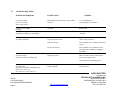
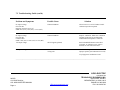
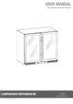
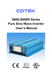
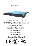
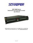
NOVA ELECTRIC CGL SERIES PURE SINE-WAVE DC-AC INVERTERS CGL 600W -SERIES INVERTER USER MANUAL NOVA ELECTRIC A DIVISION OF TECHNOLOGY DYNAMICS INC. 100 SCHOOL STREET BERGENFIELD, NJ 07621-2915 PHONE 201-385-0500 / FAX 201-385-0702 EMAIL: [email protected] WEB ADDRESS: www.novaelectric.com Features Pure Sine Wave output (<4%THD) Low power “Power Saving Mode” to conserve energy Built-in voltage and load level display on front panel Thermostatically controlled cooling fan Advanced microprocessor design Protection: • Input low voltage • Input over voltage Low battery alarm • Short circuit Applications Electronic applications: communications equipment, commercial gear, etc. Office equipment—computers, printers, monitors, facsimile machines, scanner. Mobile equipment vans. Household items – fans, fluorescent and incandescent lights, shavers, sewing machines. Small Power tools Home entertainment electronics – televisions, VCRs, video games, stereos, musical instruments, satellite equipment. NOVA ELECTRIC A DIVISION OF TECHNOLOGY DYNAMICS, INC. 045670 04/11/2003 Revision CGL 600W INVERTER MANUAL URL: www.novaelectric.com Page 2 100 SCHOOL STREET BERGENFIELD, NJ 07621-2915 PHONE 201-385-0500 FAX 201-385-0702 ELECTRICAL SPECIFICATIONS PARAMETER INPUT VOLTAGE RANGE OUTPUT VOLTAGE 110 MODEL (1) OUTPUT VOLTAGE 230V MODEL (1) OUTPUT FREQUENCY ALL UNITS (1) POWER RATING CONTINUOUS SURGE RATING PEAK OUTPUT CURRENT EFFICIENCY AT FULL LOAD NO LOAD CURRENT OUTPUT WAVEFORM OUTPUT REGULATION PROTECTION AMBIENT TEMPERATURE SIZE & WEIGHT INDICATORS 12V MODEL 24V MODEL 48 MODEL 10.7 – 15 VDC 21.5 – 32 VDC 42-58 VDC 100/110/120 VAC 100/110/120 VAC 100/110/120 VAC 220/230/240 VAC 220/230/240 VAC 220/230/240 VAC 50 OR 60 HZ Factory Selectable +/- 0.05% Accuracy 600W / 700VA 800W / 1000VA 10A (110V Models) 5A (230V Models) 83% 110V Models 87% 110V Models 87% 110V Models 86% 220V Models 90% 220V Models 90% 220V Models 0.7A for 110V Models 0.35A for 230V Models Sine Wave <4% THD -10% / +4% All Models Overload, Short Circuit, Reverse Polarity (Fuse), O..T, Over/Under Input Voltage , Fan Failure Operating: 0 to 500C Storage: -400C to 600C 270 X 180 X 72mm (10.6” x 7.1” x 2.8”) 3KG (6.6LB) INPUT LEVEL, LOAD LEVEL, FAULT NOVA ELECTRIC A DIVISION OF TECHNOLOGY DYNAMICS, INC. 045670 04/11/2003 Revision CGL 600W INVERTER MANUAL URL: www.novaelectric.com Page 3 100 SCHOOL STREET BERGENFIELD, NJ 07621-2915 PHONE 201-385-0500 FAX 201-385-0702 1. Introduction: This power inverter series are part of the most advanced line of mobile AC power systems available. This model is used in a wide range of applications including mobile equipment shelters, remote homes, RVs, sailboats and powerboats. It will operate most televisions and VCRs personal computers, small appliances and tools such as drills, sanders, grinders, mixers and blenders, within the power ratings shown in the table on the prior page. To get the most out of the power inverter, it must be installed and used properly. Please read the instructions in this manual before installing and using this model. 1. Name and Main Function: Front View: 2-1-1. ON / OFF Switch: Power ON/OFF switch: Leave in the OFF position during installation. 2-1-2. Input Level: Displays Input Voltage LED Status RED Blink (slow) RED ORANGE OFF ORANGE Blink OVER RED Blink DC 12V 10.5 ~ 10.9 10.9 ~ 11.3 11.3 ~ 12.0 12.0 ~ 14.0 14.0 ~ 14.7 14.7 ↑ DC 24 V 21.0 ~ 21.8 21.8 ~ 22.6 22.6 ~ 24.0 24.0 ~ 28.0 28.0 ~ 29.4 29.4 ↑ Load Level: Displays AC Load Watts LED Status OFF GREEN ORANGE RED RED BLINK DC 48V 42.0 ~ 43.6 43.6 ~ 45.2 45.2 ~ 48.0 48.0 ~ 56.0 56.0 ~ 58.8 58.8 ↑ Load Condition 0 ~ 30W 30W ~ 200W 200W ~ 450W 450W ~ 580W Over 580W Fault Conditions: OVP: over voltage protection UVP: under voltage protection OVER TEMP: over temperature protection OVER LOAD: over load protection INPUT LEVEL: display input voltage LOAD LEVEL: display AC load watts NOVA ELECTRIC A DIVISION OF TECHNOLOGY DYNAMICS, INC. 045670 04/11/2003 Revision CGL 600W INVERTER MANUAL URL: www.novaelectric.com Page 4 100 SCHOOL STREET BERGENFIELD, NJ 07621-2915 PHONE 201-385-0500 FAX 201-385-0702 2-1-3. AC Outlet: Outlet sockets available: Australia/New Zealand North America/US (Standard 5-15R on all 110 -110 VAC Models) Europe UK/Ireland GFCI (US Type) Rear View: 2-2-1. Ventilation window: Do not obstruct; allow at least 1 inch for air flow. 2-2-2. DC input terminals: Connect to a battery or other voltage power source of the correct voltage. [+] is positive; [-] is negative. Reverse polarity connection will blow the internal fuse and may damage the inverter permanently. The input wiring should be protected by an appropriately rated input fuse as per NEC or equivalent codes. 2-2-3. Wire to Chassis ground or to vehicle chassis using #8 AWG wire, minimum. Warning! Operation of the inverter without a proper ground connection may result in an electrical safety hazard. 3. Quick Hook-up and Testing: If you would like to hook-up the power inverter and check its performance before going ahead with your permanent installation, please follow these guidelines: 3-1. Unpack and inspect the power inverter; check to see that the power switch is in the OFF position. 3-2. Connect the cables to the power input terminals on the rear panel of the power inverter. The red terminal is positive (+) and the black terminal is negative (-). Connect the cables into the terminals and tighten the bolts to clamp the wires securely. 3-3. Connect the cable from the negative terminal of the inverter to the negative terminal of the power source. Make a secure connection. Caution! Loosely tightened connectors result in excessive drop and may cause overheated wires and melted insulation, as well as other damage. NOVA ELECTRIC A DIVISION OF TECHNOLOGY DYNAMICS, INC. 045670 04/11/2003 Revision CGL 600W INVERTER MANUAL URL: www.novaelectric.com Page 5 100 SCHOOL STREET BERGENFIELD, NJ 07621-2915 PHONE 201-385-0500 FAX 201-385-0702 3-4. Before proceeding further, carefully check that cable you have just connected is from the negative terminal of the inverter to the negative output terminal of the power source. Caution! Reverse polarity connection will blow a fuse in the inverter and may permanently damage the inverter. Damage caused by reverse polarity connection is not covered by our warranty. 3-5. Connect the cable from the positive terminal of the inverter to the positive terminal of the power source. Make a secure connection. Warning! You may observe a small spark when you make this connection since current will flow to charge capacitors in the power inverter. This can be avoided by installing a properly rated switch or circuit breaker at the power source. Do not make this connection in the presence of flammable fumes; an explosion or fire may result. 3-6. Set the power switch to the ON position. Check that the Input level indicator on the front panel of the inverter is green. If it is not, check your power source and the connections to the inverter. The other indicators should be off. 3-7. Set the power inverter switch to the OFF position. The indicator lights may blink and the internal alarm may sound momentarily. This is normal. Plug the test load into the AC receptacle on the front panel of the inverter. Leave the test load switch off. 3-8. Set the power inverter switch to the ON position and turn the test load on. The inverter should supply power to the load. If you plan to measure the true output RMS voltage of inverter, a meter such as FLUKE 87, BECKMAN 4410, or TRIPLETT 4200 must be used. 4. Installation: 4-1. Where to install. The power inverter should be installed in a location that meets the following requirements: 4-1-1. Moisture: Do not allow water to drip or splash on or in the inverter. NOVA ELECTRIC A DIVISION OF TECHNOLOGY DYNAMICS, INC. 045670 04/11/2003 Revision CGL 600W INVERTER MANUAL URL: www.novaelectric.com Page 6 100 SCHOOL STREET BERGENFIELD, NJ 07621-2915 PHONE 201-385-0500 FAX 201-385-0702 4-1-2. Cooling: Ambient air temperature should be between 0°C. and 50°C.; the cooler, the better. 4-1-3. Ventilation: Allow at least one inch of clearance around the inverter for air flow. Ensure that ventilation openings on the sides, front and rear of the unit are not obstructed. 4-1-4. Safety: Do not install in a battery compartment or other areas where flammable fumes may exist, such as fuel storage areas or engine compartments. 4-2. Cables: DC to AC inverters require high amperage / low voltage DC power low amperage / high voltage AC power. To operate properly, connect the inverter and generate DC input terminals directly to battery through a fuse or circuit breaker. The different inverters in this family require different wire sizes due to the wide input voltage choices. 4-3. Grounding: The power inverter has a lug on the rear panel [ chassis ground ]. This is to connect the chassis of the power inverter to the ground. The ground terminals in the AC outlets on the front panel of the inverter are also connected to the ground lug. The chassis ground lug must be connected to a grounding point, which will vary, depending on where the power inverter is installed. In a vehicle, connect the chassis ground to the chassis of the vehicle. In a boat, connect to the boat’s grounding systems. In a fixed location, connect the chassis ground lug to earth ground. On units with Ground Fault Circuit Interrupt (GFCI), the neutral (common) conductor of the power inverter AC output circuit is connected to the chassis ground. Therefore, when the chassis is connected to ground, the neutral conductor will also be grounded. This conforms to national electrical code requirements that separately derived AC sources (such as inverters and generators) have their neutral tied to ground in the same way that the neutral conductor from the utility line is tied to ground at the AC breaker panel. When the chassis ground lug on the rear panel is connected to an earth ground in the user’s location, it provides shock hazard protection. The GFCI has a test button and a reset button. Pushing in the test button will interrupt the output power. Pushing in the reset button will restore the output power and the green light will be on. Note: Repeated pressing/toggling of the GFCI test button may shut down the inverter AC output. THIS IS NORMAL. On units without GFCI, the neutral is floating. To conform to national electrical code requirements, the neutral must be connected to ground, or other neutrals that are grounded. NOVA ELECTRIC A DIVISION OF TECHNOLOGY DYNAMICS, INC. 045670 04/11/2003 Revision CGL 600W INVERTER MANUAL URL: www.novaelectric.com Page 7 100 SCHOOL STREET BERGENFIELD, NJ 07621-2915 PHONE 201-385-0500 FAX 201-385-0702 Warning! Do not operate the power inverter without connecting the ground terminal to ground. Electrical shock hazard may result, and the GFCI circuit will not operate properly. 5. Operation: To operate the power inverter, turn it on using the ON/OFF switch on the front panel. The power inverter is now ready to deliver AC power to your loads. If you are operating several loads from the power inverter, turn them on separately after the inverter has been turned on. This will ensure that the power inverter does not have to deliver the starting currents for all the loads at once. 5-1. Controls and Indicators: The front panel ON/OFF switch turns the control circuit in the power inverter on and off. It does not disconnect power from the power inverter. When the switch is in the OFF position, the power inverter draws no current from the battery. When the switch is in the ON position but with no load, the power inverter draws less than 1.65A / normal, 0.12A / power saving mode (12V version) from the battery. 5-2. Input Level Indicator: The input level indicator indicates the voltage at the input terminals of the power inverter. At low input current, this voltage is very close to the battery voltage. At high input current, this voltage will be lower than the battery voltage because of the voltage drop across the cable and connections. Ideally, the voltage should remain in the green. If the voltage goes into the RED area, the inverter may shut down. NOVA ELECTRIC A DIVISION OF TECHNOLOGY DYNAMICS, INC. 045670 04/11/2003 Revision CGL 600W INVERTER MANUAL URL: www.novaelectric.com Page 8 100 SCHOOL STREET BERGENFIELD, NJ 07621-2915 PHONE 201-385-0500 FAX 201-385-0702 5-3. Load Level Indicator: The load level indicator indicates the power drawn from the power inverter output. It will indicate total watts drawn by all loads. For long-term operation, the level should be in the green and orange areas of the bar graph. Short-term operation is possible with wattage in the red area. If the wattage rise to the “Blinking Red” the inverter will protect itself, and may reduce its output voltage or shut down entirely. 5-4. Fault Indicator: The over voltage indicator indicates that the power inverter has shut itself down because its input voltage has been over the high limit. 6. Operating Limits: 6-1. Power Output: Some motors used in refrigerators, freezers, pumps and other motor-operated equipment require very high surge currents to start, often as much as 6 – 7 times rated. The power inverter may not be able to start some of these motors, even though their rated current draw is within the power inverter. If the motor refuses to start, observe the battery voltage indicator while trying to start the motor. If the battery voltage indicator drops below the low input level while the inverter is attempting to start the motor, this may be the reason the motor won’t start. Make sure that the battery connections are good and that the battery is fully charged. If the connections are good and the battery is charged, but the voltage still drops below the low voltage level, you may need to use a larger battery, or larger wire. 6-2. Input Voltage: The power inverter will operate from input voltages ranging from 10.9V – 14.7V (12V version) 21.8V – 29.4V (24V version), or 43.6V - 58.5V (48V version). If the voltage drops below 10.5V (12V version), 21V (24V version), an audible low battery warning will sound and the voltage indicator will be in slow blinking red. The power inverter will shut down if the input voltage drops below 10V (12V version), 20V (24V version), or 40V (48V version). This protects your battery from being over discharged. NOVA ELECTRIC A DIVISION OF TECHNOLOGY DYNAMICS, INC. 045670 04/11/2003 Revision CGL 600W INVERTER MANUAL URL: www.novaelectric.com Page 9 100 SCHOOL STREET BERGENFIELD, NJ 07621-2915 PHONE 201-385-0500 FAX 201-385-0702 The power inverter will also shut down if the input voltage exceeds its rating. This protects the inverter against excessive input voltage. The input level will be red blinking. Although the power inverter incorporates protection against over voltage, it may still be damaged if the input voltage is allowed to exceed 20V (12V version) or 40V (24V version). or 75V (48V version). 7. Troubleshooting: 7-1. Common Problems: Television or other communication equipment interference: Operation of the power inverter can interfere with television reception on some channels. If this situation occurs, the following steps may help to alleviate the problem. • Make sure that the chassis ground lug on the back of the power inverter is solidly connected to the ground system of your vehicle, boat, shelter, or home. • Make sure the neutral is bonded to ground ( See page 7) • Move the television as far away from the power inverter as possible. • Keep the cables between the battery and the power inverter as short as possible and twist them together with about 2 to 3 twists per foot. This minimizes radiated interference from the cables. Overheating: Check for clean air intake and an exhaust opening, and check that the fan is operating. No Output: Check the input fuses (remove cover). Check for correct input voltage NOVA ELECTRIC A DIVISION OF TECHNOLOGY DYNAMICS, INC. 045670 04/11/2003 Revision CGL 600W INVERTER MANUAL URL: www.novaelectric.com Page 10 100 SCHOOL STREET BERGENFIELD, NJ 07621-2915 PHONE 201-385-0500 FAX 201-385-0702 7-2 Troubleshooting Guide: Problem and Symptoms Possible Cause Low output voltage (110V: 95-105VAC, 220V: 190-210VAC) Bad readings caused by using average reading voltmeter Use a true RMS meter (See paragraph 3.8 of manual ) Load level LED is RED Flashing No output voltage and Input level indicator is red blinking Overload Reduce load Low input voltage Recharge battery, check connections and cable. No output voltage, No voltage indication Inverter switched off. No power to the inverter. Turn inverter on. Check wiring to Inverter. Internal fuse open Have qualified service technician check and replace. Reverse DC Polarity Have qualified service technician check and replace fuse, OBSERVE CORRECT POLARITY High input voltage Make sure that inverter is connected to a proper input voltage source. No output voltage. Input level indicator is blinking fast Solution Check regulation of charging system. Low battery alarm ON all the time, Voltage level indicator is blinking slowly Below 10.5V (12V ver.), 21V (24V ver.), or 42V (48V ver.) Poor DC wiring, poor battery condition Use proper cable and make solid connection. Use new battery. NOVA ELECTRIC A DIVISION OF TECHNOLOGY DYNAMICS, INC. 045670 4/11/2003 Revision CGL 600W INVERTER MANUAL URL:www.novaelectric.com Page 11 100 SCHOOL STREET BERGENFIELD, NJ 07621-2915 PHONE 201-385-0500 FAX: 201-385-0702 7.2 Troubleshooting Guide (cont’d.) Problem and Symptoms Possible Cause No output voltage, Unit feels hot Input DC current in excess of: 600W: 60A (12V), 30A (24V), or 16A (48V) Thermal shutdown Allow inverter to cool off. Reduce load if continuous operation required. No output voltage, Unit feels hot Load less than: 600W: 60A (12V) or 30A (24V) or 16A (48V) No output voltage Thermal shutdown Improve ventilation. Make sure ventilation openings in inverter are not obstructed; reduce ambient temperature. Check fan GFCI Tripped (optional) Push in the RESET button on the GFCI receptacle. It continues to trip, remove the load see if the load is the cause. Short circuit or wiring error. Check AC wiring for short circuit or improper polarity (hot and neutral reversed) No output voltage; Solution Very high power load Remove load __________________________________________________________________________________________________________________________ NOVA ELECTRIC A DIVISION OF TECHNOLOGY DYNAMICS, INC. 045670 4/11/2003 Revision CGL 600W INVERTER MANUAL URL:www.novaelectric.com Page 12 100 SCHOOL STREET BERGENFIELD, NJ 07621-2915 PHONE 201-385-0500 FAX: 201-385-0702 8. Maintenance: Very little maintenance is required to keep your inverter operating properly. You should clean the exterior of the unit periodically with a damp cloth to prevent accumulation of dust and dirt. At the same time, tighten the screws on the DC input terminals. ( Remove power first) 9. The Output Voltage and Frequency is factory preset. No external adjustments are available for these two parameters 10. Warranty: All Nova Electric products are warranted against defects in material and workmanship for a period of one year from shipping date. Our obligation includes replacing, repairing, or adjusting products (excluding fuses) that prove to be defective during the warranty period. The unit must be returned to us postage paid. Contact our Customer Service Manager at (201) 385-0500 (Extension 115 ) for a Return Material Authorization (RMA) number. This warranty is fully transferable. If a product is sold to a manufacturer for use in a product for resale, the complete warranty is in force, providing the power system is sold as original equipment. This warranty will be considered void if the unit has suffered any obvious physical damage or alteration, either internally or externally, and does not cover damage arising from improper use, such as plugging the unit into an unsuitable or reversed power source, attempting to operate products with excessive power consumption requirements, or use in unsuitable climates. Nova Electric assumes no liabilities for consequential damages of any kind through the use or misuse of its products by the purchaser or others. No other obligations are expressed or implied. NOVA ELECTRIC A DIVISION OF TECHNOLOGY DYNAMICS, INC. 045670 04/11/2003 Revision CGL 600W INVERTER MANUAL URL: www.novaelectric.com Page 13 100 SCHOOL STREET BERGENFIELD, NJ 07621-2915 PHONE 201-385-0500 FAX 201-385-0702