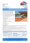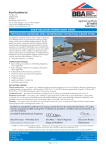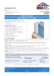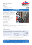
1
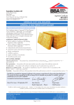
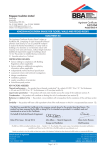
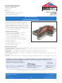
Recticel Insulation Products APPROVAL INSPECTION TESTING CERTIFICATION (a division of Recticel Ltd) Enterprise Way Meir Park Stoke on Trent Staffordshire ST3 7UN Tel: 01782 590470 Fax: 01782 590497 TECHNICAL APPROVALS FOR CONSTRUCTION Agrément Certificate 02/3908 e-mail: [email protected] website: www.recticelinsulation.co.uk Product Sheet 1 RECTICEL INSULATION RECTICEL EUROWALL CAVITY This Agrément Certificate Product Sheet(1) relates to Recticel Eurowall Cavity, a rigid polyisocyanurate board faced on both sides with low emissivity facings. The product is installed during construction and is for use as a partial fill board to reduce the thermal transmittance of cavity walls in new buildings with masonry inner and outer leaves and a minimum residual cavity of 50 mm. (1) Hereinafter referred to as ‘Certificate’. CERTIFICATION INCLUDES: • factors relating to compliance with Building Regulations where applicable • factors relating to additional non-regulatory information where applicable • independently verified technical specification • assessment criteria and technical investigations • design considerations • installation guidance • regular surveillance of production • formal three-yearly review. KEY FACTORS ASSESSED Thermal performance — the product has a declared thermal conductivity (D value) of 0.022 W·m–1·K–1 and an aged emissivity of 0.05 for the facing (see section 6). Watertightness — the product will resist water transfer across the cavity of the walls (see section 7). Condensation — the product will contribute to limiting the risk of condensation (see section 8). Behaviour in relation to fire — the product, once installed in the wall, will not prejudice the fire resistance of the wall (see section 9). Durability — the product will have a life equivalent to that of the wall structure in which it is incorporated (see section 12). The BBA has awarded this Certificate to the company named above for the product described herein. This product has been assessed by the BBA as being fit for its intended use provided it is installed, used and maintained as set out in this Certificate. On behalf of the British Board of Agrément Date of Second issue: 11 September 2013 John Albon — Head of Approvals Claire Curtis-Thomas Originally certificated on 22 March 2002 Energy and Ventilation Chief Executive The BBA is a UKAS accredited certification body — Number 113. The schedule of the current scope of accreditation for product certification is available in pdf format via the UKAS link on the BBA website at www.bbacerts.co.uk Readers are advised to check the validity and latest issue number of this Agrément Certificate by either referring to the BBA website or contacting the BBA direct. British Board of Agrément Bucknalls Lane Watford Herts WD25 9BA ©2013 Page 1 of 11 tel: 01923 665300 fax: 01923 665301 e-mail: [email protected] website: www.bbacerts.co.uk Regulations In the opinion of the BBA, Recticel Eurowall Cavity, if installed, used and maintained in accordance with this Certificate, will meet or contribute to meeting the relevant requirements of the following Building Regulations (the presence of a UK map indicates that the subject is related to the Building Regulations in the region or regions of the UK depicted): The Building Regulations 2010 (England and Wales) (as amended) Requirement: C2(a) Resistance to moisture Comment: Requirement: C2(c) Resistance to moisture Comment: Requirement: L1(a)(i) Conservation of fuel and power Comment: Regulation: 7 Materials and workmanship Comment: Regulation: 26 CO2 emission rates for new buildings The product can contribute to satisfying this Requirement. See section 7.1 of this Certificate. The product can contribute to satisfying this Requirement. See sections 8.1 and 8.3 of this Certificate. The product can contribute to satisfying this Requirement. See sections 6.1 and 6.3 of this Certificate. The product is acceptable. See section 12 and the Installation part of this Certificate. The product can contribute to satisfying this Regulation. See sections 6.1 and 6.3 of this Certificate. Comment: The Building (Scotland) Regulations 2004 (as amended) Regulation: 8(1) Durability, workmanship and fitness of materials Comment: Regulation: Standard: 9 3.4 Building standards applicable to construction Moisture from the ground The product is acceptable. See section 12 and the Installation part of this Certificate. The product can contribute to satisfying this Standard, with reference to clauses 3.4.1(1) and 3.4.5(1)(2). See section 7.1 of this Certificate. Comment: Standard: 3.15 Standard: Standard: 6.1(b) 6.2 7.1(a)(b) Statement of sustainability The product can contribute to satisfying the relevant requirements of Regulation 9, Standards 1 to 6, and, therefore, will contribute to a construction meeting a bronze level of sustainability as defined in this Standard. See section 6.1 of this Certificate. In addition, the product can contribute to a construction meeting a higher level of sustainability as defined in this Standard, with reference to clauses 7.1.4(1)(2) [Aspects 1(1)(2) and 2(1)], 7.1.6(1)(2) [Aspects 1(1)(2) and 2(1)] and 7.1.7(1)(2) [Aspect 1(1)(2)]. See section 6.1 of this Certificate. Comment: Regulation: Carbon dioxide emissions Building insulation envelope The product can contribute to satisfying this Standard, with reference to with clauses, or parts of clauses, 6.1.1(1), 6.1.2(1)(2), 6.1.6(1), 6.2.1(1)(2), 6.2.3(1), 6.2.9(1), 6.2.11(1)(2) and 6.2.12(2). See sections 6.1 and 6.3 of this Certificate. Comment: Standard: Condensation The product can contribute to satisfying this Standard, with reference to clauses 3.15.1(1), 3.15.3(1) and 3.15.4(1). See sections 8.2 and 8.3 of this Certificate. Comment: 12 Building standards applicable to conversions All comments given for this product under Regulation 9, Standards 1 to 6, also apply to this Regulation, with reference to clause 0.12.1(1) and Schedule 6(1). Comment: (1) Technical Handbook (Domestic). (2) Technical Handbook (Non-Domestic). The Building Regulations (Northern Ireland) 2012 Regulation: 23 Fitness of materials and workmanship Comment: Regulation: 28(a) Resistance to moisture and weather Comment: Regulation: 29 Condensation Comment: Regulation: Regulation: 39(a)(i) 40(2) Conservation measures Target carbon dioxide emission rate Comment: The product is acceptable. See section 12 and the Installation part of this Certificate. The product can contribute to satisfying this Regulation. See section 7.1 of this Certificate. The product can contribute to satisfying this Regulation. See section 8.3 of this Certificate. The product can contribute to satisfying these Regulations. See sections 6.1 and 6.3 of this Certificate. Construction (Design and Management) Regulations 2007 Construction (Design and Management) Regulations (Northern Ireland) 2007 Information in this Certificate may assist the client, CDM co-ordinator, designer and contractors to address their obligations under these Regulations. See section: 3 Delivery and site handling (3.3) of this Certificate. Page 2 of 11 Additional Information NHBC Standards 2013 NHBC accepts the use of Recticel Eurowall Cavity, provided it is installed and used in accordance with this Certificate, in relation to NHBC Standards, Chapter 6.1 External masonry walls. CE marking The Certificate holder has taken the responsibility of CE marking the product in accordance with harmonised European Standard BS EN 13165 : 2012. An asterisk (*) appearing in this Certificate indicates that data shown is given in the manufacturer’s Declaration of Performance. Technical Specification 1 Description Recticel Eurowall Cavity consists of a core of rigid polyisocyanurate board faced on either side by an aluminium foil/ kraft paper laminate. The nominal characteristics are given in Table 1. Table 1 Nominal characteristics (1) Characteristic Value Length* (mm) 1200 Width* (mm) 450 Thickness* (mm) 25-100 Nominal density (kg·m–3) 30 Edge profile square edge 2 Manufacture 2.1 The product is manufactured in accordance with the BS EN 13165 : 2012 and consists of a rigid polyisocyanurate board faced with aluminium/kraft laminate during the process. 2.2 As part of the assessment and ongoing surveillance of product quality, the BBA has: • agreed with the manufacturer the quality control procedures and product testing to be undertaken • assessed and agreed the quality control operated over batches of incoming materials • monitored the production process and verified that it is in accordance with the documented process • evaluated the process for management of nonconformities • checked that equipment has been properly tested and calibrated • undertaken to carry out the above measures on a regular basis through a surveillance process, to verify that the specifications and quality control operated by the manufacturer are being maintained. 2.3 The management system of Recticel Insulation Products has been assessed and registered as meeting the requirements of BS EN ISO 9001 : 2008 by Lloyd’s Register Quality Assurance (Certificate 951267). 3 Delivery and site handling 3.1 The product is delivered to site in polythene wrapped packs. The grade, manufacturer’s trade name and BBA logo incorporating the Certificate number are printed on every pack. 3.2 The product must be protected from prolonged exposure to sunlight and should be stored either under cover or protected with light-coloured, opaque polythene sheets. Where possible, packs should be stored inside. If stored outside, the product should be raised above ground level out of contact with ground moisture, and must be protected from rain. 3.3 The product must not be exposed to naked flame or other ignition sources. Care must be taken to avoid contact with solvents and with materials containing volatile organic compounds. If damaged, the product should be discarded. Assessment and Technical Investigations The following is a summary of the assessment and technical investigations carried out on Recticel Eurowall Cavity. Page 3 of 11 Design Considerations 4 Use 4.1 Recticel Eurowall Cavity is effective in reducing the U value (thermal transmittance) of new external cavity walls with masonry inner and outer leaves (masonry includes clay and calcium silicate bricks, concrete blocks, natural and reconstituted stone blocks). It is essential that the residual cavity is of a minimum such walls are designed and constructed to incorporate the normal precautions to prevent moisture penetration. 4.2 Buildings subject to the national Building Regulations should be constructed in accordance with the relevant recommendations of: • • • • BS BS BS BS EN 1996-1-1 : 2005 EN 1996-2 : 2006 EN 1996-3 : 2006 8000-3 : 2001. 4.3 Other buildings not subject to these Regulations should also be built in accordance with the Standards given in section 4.2. 4.4 Wall ties and fixings and if required any additional twist ties to BS EN 845-1 : 2003 should be used for structural stability in accordance with BS EN 1996-1-1 : 2005, BS EN 1996-2 : 2006 and BS EN 1996-3 : 2006 where the overall cavity width exceeds 75 mm. 4.5 The use of cavity battens or boards is strongly recommended to prevent thermal bridging by mortar droppings. 4.6 As with any other form of cavity wall insulation, where buildings need to comply with NHBC Standards 2013, specifiers should observe the requirements of these Standards. Buildings up to and including 12 metres high 4.7 The product can be used in any exposure zone. However, the use of the product does not preclude the need to apply any external render coat or other suitable finish in severe exposure zones where such application would be normal practice. 4.8 The nominal residual cavity width is to be maintained during construction, subject to the limitations in respect of exposure of the proposed building as set out in Table 2. Table 2 Maximum allowable total exposure factors of different constructions Construction Maximum allowable exposure factor E All external masonry walls protected by: rendering (to BS EN 13914-1 : 2005) tile hanging slate hanging timber, plastic or metal weatherboarding or cladding no restriction One or more external masonry walls constructed from facing clay brickwork or natural stone, the porosity of which exceeds 20% by volume. Mortar joints must be flush pointed or weatherstruck 100 One or more external masonry walls constructed from calcium silicate bricks, concrete blocks, reconstituted stone or natural stone, the porosity of which is less than 20% by volume, or any material with raked mortar joints 88 (1) Based upon the approach in BS 5618 : 1985 and also outlined in BBA information sheet No 10. Buildings over 12 metres in height 4.9 In addition to the above, the following requirements apply: • from ground level the maximum height of continuous cavity walls must not exceed 12 metres; above 12 metres the maximum height of continuous cavity walls must not exceed 7 metres. In both cases, breaks should be in the form of continuous horizontal cavity trays discharging to the outside • the specifier must take extra care when detailing to ensure that the introduction of the insulation does not affect the weather resistance of the wall. More than average site supervision is recommended during installation of the product • the exposure factor or index must not exceed 120 • where, for structural reasons, the cavity width is reduced, eg by the intrusion of ring beams, a minimum residual cavity width of 25 mm must be maintained and extra care must be taken with fixings and weatherproofing, eg the inclusion of a cavity tray. 5 Practicability of installation The product is designed to be installed by a competent general builder, or a contractor, experienced with this type of product. Page 4 of 11 6 Thermal performance 6.1 Calculations of thermal transmittance (U value) should be carried out in accordance with BS EN ISO 6946 : 2007 and BRE Report BR 443 : 2006, using the declared thermal conductivity D value)* of 0.022 W·m–1·K–1 for the insulations and the aged emissivity of the foil-facing is 0.05 to BS EN 15976 : 2011. 6.2 The U value of a completed wall will depend on the selected insulation thickness, number and type of fixings, the insulating value of the substrate masonry and its internal finish. Calculated U values for example constructions are given in Table 3. Table 3 Example U values(1)(2)(3)(4) U value W·m–2·K–1) Thickness of product required (mm) AAC block ( = 0.12 W·m–1·K–1) Dense block ( = 1.13 W·m–1·K–1) 0.19 75 90 0.26 45 60 0.28 40 55 0.30 35 50 25 35 0.35 (1) Assumes stainless steel fixings ( = 17 W·m ·K ) correction Uf <3% of nominal U value and 102 mm thick brick outer leaf and mortar thermal conductivity: 0.88 W·m–1·K–1. (2) Plaster on dabs thermal conductivity: 0.43 W·m–1·K–1. (3) Plasterboard: thermal conductivity: 0.25 W·m–1·K–1. (4) Percentage of overprint on the foil is less than 2%. –1 –1 6.3 The product can maintain, or contribute to maintaining, the continuity of thermal insulation at junctions between elements and openings. For Accredited Construction Details the corresponding -values (psi) in BRE Information Paper IP 1/06, Table 3, may be used in carbon emission calculations in Scotland and Northern Ireland. Detailed guidance for other junctions and on limiting heat loss by air infiltration can be found in: England and Wales — Approved Documents to Part L and for new thermal elements to existing buildings, Accredited Construction Details (version 1.0). See also SAP 2009 Appendix K and the iSBEM User Manual for new-build Scotland — Accredited Construction Details (Scotland) Northern Ireland — Accredited Construction Details (version 1.0). 6.4 The Certificate holder has at least one member of staff who has been deemed competent by the BBA under the BBA/TIMSA Scheme for Calculation Competency (U value and Condensation Risk Analysis). Competent persons should be contacted for accurate, quality-assured U value and condensation risk analysis. The Certificate of Competency can be found on the BBA website (http://www.bbacerts.co.uk) as Certificate CS/1003. 7 Watertightness 7.1 When the product is used in situations where it bridges the damp-proof course (dpc) in walls, dampness from the ground will not pass through to the inner leaf provided the wall is detailed in accordance with the requirements and provisions of the national Building Regulations: England and Wales — Approved Document C, Section 5 Scotland — Mandatory Standard 3.4, clauses 3.4.1(1) and 3.4.5(1)(2) (1) Technical Handbook (Domestic). (2) Technical Handbook (Non-Domestic). Northern Ireland — Technical Booklet C, Section 6 7.2 Constructions incorporating the product and built in accordance with the Standards listed in section 4.2, will resist the transfer of precipitation to the inner leaf and satisfy the national Building Regulations: England and Wales — Requirement C2 Scotland — Mandatory Standard 3.10, clause 3.10.5(1)(2) (1) Technical Handbook (Domestic). (2) Technical Handbook (Non-Domestic). Northern Ireland — Technical Booklet C, Section 6. 7.3 In all situations it is particularly important to ensure during installation that: • wall ties and fixings are installed correctly and are thoroughly clean • excess mortar is cleaned from the cavity face of the leading leaf and any debris removed from the cavity • mortar droppings are cleaned from the exposed edges of installed boards Page 5 of 11 • boards are properly installed and butt jointed • installation is carried out to the highest level on each wall or the top edge of the insulation is protected by a cavity tray • at lintel level, a cavity tray, stopends and weep holes, must be provided. 8 Condensation Surface condensation 8.1 Walls will limit the risk of surface condensation adequately when the thermal transmittance (U value) does not exceed 0.7 W·m–2·K–1 at any point, and the junctions with floors, roofs and openings are designed in accordance with the TSO publication Limiting thermal bridging and air leakage : Robust construction details for dwellings and similar buildings or BRE Information Paper IP 1/06. 8.2 Walls will adequately limit the risk of surface condensation when the thermal transmittance (U value) does not exceed 1.2 W·m–2·K–1 at any point. Guidance may be obtained from BS 5250 : 2011, Annex G, and BRE Report BR 262 : 2002. Interstitial condensation 8.3 Walls will limit the risk of interstitial condensation adequately when they are designed and constructed in accordance with BS 5250 : 2011 (Annexes D and G). 8.4 The core of the product has a water vapour resistivity of 300 MN·s·g–1·m–1, and a water vapour resistance of 4000 MN·s·g–1 for the facing. 9 Behaviour in relation to fire 9.1 The product does not prejudice the fire resistance properties of walls. The board is unlikely to become ignited within the cavity when used in the context of this Certificate. If fire does penetrate into an unventilated cavity, the amount of air present will be insufficient to support combustion, and flame spread will be minimal. 9.2 The requirements of the Building Regulations relating to fire spread in cavity walls, can be met in buildings of all purpose groups without the need for cavity barriers, provided the construction complies with the provisions detailed in: England and Wales — Approved Document B, Diagram 32 Northern Ireland — Technical Booklet E, Diagram 4.5. 9.3 A summary of these provisions is given here: • the wall must consist of masonry inner and outer leaves, each at least 75 mm thick • the cavity must not be more than 300 mm wide (Northern Ireland only) • the cavity must be closed at the top of the wall and at the top of any opening • in addition to the insulation, only the following features should be placed in, or exposed to, the cavity: — timber lintels, window or door frames, or end of timber joists — pipe, conduit or cables — dpc, flashing, cavity closer or wall tie — domestic meter cupboard, provided there are not more than two cupboards to a dwelling, the opening in the outer leaf is not more than 800 mm by 500 mm for each cupboard, and the inner leaf is not penetrated except by a sleeve not more than 80 mm by 80 mm, which is fire-stopped. 9.4 For constructions not covered by sections 9.2 and 9.3, cavity barriers must be provided to comply with: England and Wales — Approved Document B, Volume 1, Section 6 and Volume 2, Section 9 Scotland — Mandatory Standard 2.4, clauses 2.4.1(1)(2), 2.47(1)(2) and 2.49(2) (1) Technical Handbook (Domestic). (2) Technical Handbook (Non-Domestic). Northern Ireland — Technical Booklet E, paragraphs 4.36 to 4.39. 9.5 In Scotland, as the product is combustible it may be used in walls of buildings with no storey at a height of more than 18 m above the ground that are on or less than one metre from a relevant boundary. 10 Proximity of flues and appliances When installing the product in close proximity to certain flue pipes and/or heat-producing appliances, the following provisions to the national Building Regulations are acceptable: England and Wales — Approved Document J, sections 1 to 4 Scotland — Mandatory Standard 3.19, clauses 3.19.1(1)(2) to 3.19.9(1)(2) (1) Technical Handbook (Domestic). (2) Technical Handbook (Non-Domestic). Technical Standards, Part F, Provisions deemed to satisfy the Technical Standards Northern Ireland — Technical Booklet L, section 2. Page 6 of 11 11 Maintenance As the product is confined within the wall cavity and it has suitable durability (see section 12), maintenance is not required. 12 Durability The product is dimensionally stable, rot-proof and durable, and will remain effective as an insulant for the life of the building. Installation 13 General It is recommended that the inner leaf be constructed ahead of the outer leaf, as boards fastened to the cavity face of the inner leaf give a slightly enhanced thermal performance. It is essential that the spacing of the wall ties/clips allows the long edge of each board to be secured at a minimum of two points. 14 Procedure 14.1 A section of the inner leaf is built with the first row of wall ties, at approximately 600 mm horizontal spacing, where the insulation is to begin. The wall ties should not be placed directly on the dpc. The first run of boards should commence below the dpc level to provide some edge insulation for the floor (see Figure 1). Figure 1 Typical installation first run commences below dpc level, to provide some edge insulation for floor 14.2 The leading leaf is built up to the required height, with wall ties placed at a vertical height of 450 mm ensuring the drip of the tie is located halfway across the residual cavity width. Excess mortar is cleaned from the cavity face of the leading leaf, and the boards are placed on the wall ties, behind the retaining clips, to form a closely butt-jointed run. 14.3 The second row of wall ties is fitted to retain the tops of the boards. It is essential that all wall ties slope downwards towards the outer leaf (see Figure 2) and are placed at centres not exceeding 900 mm to ensure that each board is secured at a minimum of three points. It is also important that the first row of insulation should not be in contact with the ground. Page 7 of 11 Figure 2 Installation of wall ties wall ties must slope down towards outer leaf dpc 14.4 Additional wall ties may be required to satisfy the structural requirements of BS EN 845-1 : 2003, BS EN 1996-1-1 : 2005, BS EN 1996-2 : 2006 and BS EN 1996-3 : 2006 to ensure adequate retention of boards or cut pieces. 14.5 The other leaf is built up to the level of the top of the boards. 14.6 All boards should be butted with vertical joints staggered. Insulation boards and wall ties should be staggered as construction proceeds and carried up to the highest level of wall, except where protected by a cavity tray. Mortar droppings 14.7 After each section of the leading leaf is built, excess mortar should be removed from the cavity face and mortar droppings cleaned from exposed edges of the installed board, before installation of the next run of boards. Use of a cavity board or a cavity batten will protect the installed board edges and help to keep the cavity clean as the following leaf is built (see Figures 3 and 4). Figure 3 Use of cavity board Page 8 of 11 Figure 4 Use of cavity batten Wall openings 14.8 Where openings such as doors and windows are in close proximity, it is recommended that a continuous lintel or cavity tray is used. Individual lintels or cavity trays should have stopends and be adequately drained. Cut pieces 14.9 Boards can be cut, using a sharp knife or fine-toothed saw, to fit openings, eg around windows, doors and air bricks. It is essential that cut pieces of board completely fill the spaces for which they are intended and are adequately secured. Protection 14.10 All building involving the product, particularly interrupted work, must conform to BS EN 1996-2 : 2006, Sections 3.2 Acceptance, handling and storage of materials and 3.6 Curing and protective procedures during execution. Technical Investigations 15 Investigations An examination was made of test data relating to: • water vapour resistance • density • thermal conductivity • closed cell count • compressive strength at 10% strain • water absorption • dimensional accuracy • dimensional stability with temperature and humidity • cross-breaking strength • condensation risk. Page 9 of 11 Bibliography BS 5250 : 2011 Code of practice for control of condensation in buildings BS 5618 : 1985 Code of practice for thermal insulation of cavity walls (with masonry or concrete inner and outer leaves) by filling with urea-formaldehyde (UF) foam systems BS 8000-3 : 2001 Workmanship on building sites — Code of practice for masonry BS EN 845-1 : 2003 Specification for ancillary components for masonry — Ties, tension straps, hangers and brackets BS EN 1996-1-1 : 2005 Eurocode 6 : Design of masonry structures — General rules for reinforced and unreinforced masonry structures BS EN 1996-2 : 2006 Eurocode 6 : Design of masonry structures — Design considerations, selection of materials and execution of masonry BS EN 1996-3 : 2006 Eurocode 6 : Design of masonry structures : Simplified calculation methods for unreinforced masonry structures BS EN 13165 : 2012 Thermal insulation products for buildings — Factory made rigid polyurethane foam (PU) products — Specification BS EN 13914-1 : 2005 Design, preparation and application of external rendering and internal plastering — External rendering BS EN 15976 : 2011 Flexible sheets for waterproofing — Determination of emissivity BS EN ISO 6946 : 2007 Building components and building elements — Thermal resistance and thermal transmittance — Calculation method BS EN ISO 9001 : 2008 Quality management systems — Requirements BRE Information Paper IP 1/06 Assessing the effects of thermal bridging at junctions and around openings BRE Report (BR 262 : 2002) Thermal insulation: avoiding risks BRE Report (BR 443 : 2006) Conventions for U-value calculations Page 10 of 11 Conditions of Certification 16 Conditions 16.1 This Certificate: • relates only to the product/system that is named and described on the front page • is issued only to the company, firm, organisation or person named on the front page — no other company, firm, organisation or person may hold or claim that this Certificate has been issued to them • is valid only within the UK • has to be read, considered and used as a whole document — it may be misleading and will be incomplete to be selective • is copyright of the BBA • is subject to English Law. 16.2 Publications, documents, specifications, legislation, regulations, standards and the like referenced in this Certificate are those that were current and/or deemed relevant by the BBA at the date of issue or reissue of this Certificate. 16.3 This Certificate will remain valid for an unlimited period provided that the product/system and its manufacture and/or fabrication, including all related and relevant parts and processes thereof: • are maintained at or above the levels which have been assessed and found to be satisfactory by the BBA • continue to be checked as and when deemed appropriate by the BBA under arrangements that it will determine • are reviewed by the BBA as and when it considers appropriate. 16.4 The BBA has used due skill, care and diligence in preparing this Certificate, but no warranty is provided. 16.5 In issuing this Certificate, the BBA is not responsible and is excluded from any liability to any company, firm, organisation or person, for any matters arising directly or indirectly from: • the presence or absence of any patent, intellectual property or similar rights subsisting in the product/system or any other product/system • the right of the Certificate holder to manufacture, supply, install, maintain or market the product/system • actual installations of the product/system, including their nature, design, methods, performance, workmanship and maintenance • any works and constructions in which the product/system is installed, including their nature, design, methods, performance, workmanship and maintenance • any loss or damage, including personal injury, howsoever caused by the product/system, including its manufacture, supply, installation, use, maintenance and removal • any claims by the manufacturer relating to CE marking. 16.6 Any information relating to the manufacture, supply, installation, use, maintenance and removal of this product/ system which is contained or referred to in this Certificate is the minimum required to be met when the product/system is manufactured, supplied, installed, used, maintained and removed. It does not purport in any way to restate the requirements of the Health and Safety at Work etc. Act 1974, or of any other statutory, common law or other duty which may exist at the date of issue or reissue of this Certificate; nor is conformity with such information to be taken as satisfying the requirements of the 1974 Act or of any statutory, common law or other duty of care. British Board of Agrément Bucknalls Lane Watford Herts WD25 9BA ©2013 Page 11 of 11 tel: 01923 665300 fax: 01923 665301 e-mail: [email protected] website: www.bbacerts.co.uk