1
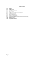
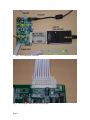
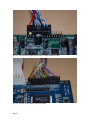
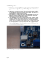
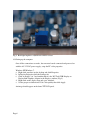
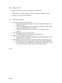
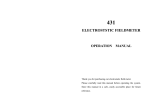
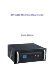
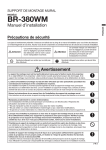
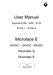
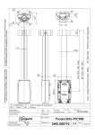
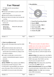
Design Accelerator Kit
TFT
User Manual
Version 1.10
June 23rd, 2011
Mitsubishi Electric
Copyright reserved
Page1
Table of content
1.0
2.0
3.0
4.0
5.0
6.0
7.0
8.0
9.0
10.0
11.0
Page2
Preface
DAK content
Demo PC requirements
Kit assembly
USB video controller driver installation
Connection to panel
LED backlight driver
Setting up the computer
DVI-LVDS/CMOS Converter board On Screen Display
Running a demo
FAQ/Trouble shooting
1.0 Preface
This Design Accelerator Kit is made to help demonstrate Mitsubishi Electric industrial
displays. It along with other versions covers both LVDS and CMOS interface products
in popular resolutions. For specific questions not covered by this document, please
contact your sales representative or Mitsubishi Electric technical personnel.
2.0 DAK content
a.
b.
c.
d.
e.
f.
USB-DVI video controller, driver CD
DVI-DVI adapter/cable eliminator
DVI-LVDS or DVI-CMOS signal converter, keyboard (resolution specific)
LVDS or CMOS panel cable
LED backlight driver and cables
AC120/240-DC 12V power supply
3.0 Demo PC requirements
This kit will work with a wide variety of PC configurations. Generally, the following
are major options:
a. PC with DVI port such as Macbook
A standard DVI-DVI cable can be used and the USB-DVI video controller will
not be need.
b. PC with HDMI port
A standard HDMI-DVI cable can be used and the USB-DVI video controller will
not be needed.
c. PC with no DVI or HDMI video out
An USB-DVI video controller is included in the kit for your convenience. Please
follow section 5 to install the USB video controller driver.
4.0 Kit assembly
Caution: electronic assemblies in the DAK are susceptible to ESD. Make sure you
are properly grounded before proceeding.
a. Connect the USB-DVI video controller and DVI-LVDS/CMOS converter using
the DVI-DVI adapter/cable eliminator. Secure with the thumb screws (Fig 1).
b. Attach small OSD keypad using the 8 conductor cable provided. The connector
on the converter has 10 positions and two pins on the end are left open (Fg 2).
c. Insert LVDS cable connector to panel. Pin 1 on the cable connector is marked
with a white dot and some pins on the converter board may be left open (Fig 3).
d. Insert LED backlight driver cable connector to panel. This is a 6 pin white
connector and 4 conductors are used. Some signal converter boards have
integrated LED backlight driver. For CCFL inverter applications, contact your
sales representative.
e. The panel voltage jumper should be set to 3V.
Page3
Fig 1 Kit components connected
Fig.2, OSD keypad connector, note two open pins.
Page4
Fig. 3a Ten pins to the right are left open, LVDS converter board.
Fig. 3b All pins used, CMOS converter board.
Page5
5.0 USB video controller driver installation
Insert USB-DVI video controller driver CD in computer DVD reader drive. Follow
on screen instruction to install the driver. After driver installation is confirmed, insert
the USB cable to an available USB port. When the OS properly recognizes the video
controller, the small LED on the video controller should illuminate.
6.0 Connection to panel
a. LVDS version
Connect the LVDS cable JST connector end to the panel and pin header end to the
30 pin header on the converter board (Fig 4).
b. CMOS version
Connect the CMOS cable 31 pin Hirose connector end to the panel and 40 pin
header to the 40 pin header on the converter board (Fig. 5).
c. LED backlight connection
Insert the 6 pin JST connector from LED driver board to the panel (Fig. 6). Some
TFT panel models use 4 string LED with a 10 pin JST connector. In that case
request a 4 string LED, dual driver board kit from your sales rep or Mitsubishi
Electric technical support staff.
Fig. 4 LVDS cable connector on LCD panel
Caution: Check datasheet for pin 1 location. In this photo, cable end pin 1 is to the right.
Page6
Fig. 5 CMOS cable connector on LCD panel
Fig. 6 LED backlight connector. This connector only goes in one way.
Page7
7.0 LED Backlight Driver
a. Some kits use an integrated LED driver on the signal converter board. Look for a
connector shown in Fig 7. The two pin LED backlight cable should be inserted
here.
b. Some kits use a separate driver board. This board should be connected to the 6
pin backlight power connector on the signal converter board. The cable to LCD
backlight should be attached to the driver board.
c. Most high bright LCD panels with 4 strings LED backlight and above will need
LED driver boards not included in the kits. Please consult with our sales and
technical staff for the proper LED driver solutions.
d. The LED backlight in our LCDs are constant current design. Brightness can be
adjusted to datasheet value by adjusting the LED driver board output current to
datasheet value. Some signal converter boards have a variable resistor for this
purpose (Fig 8). In the absence of this variable resistor, a variable resistor should
be added on the ADJ line of the 6 pin connector and cable assembly to properly
adjust backlight brightness. Use of the brightness control in OSD function does
not properly adjust backlight brightness.
Fig. 7 LED backlight driver output connector.
Page8
Fig. 8 Backlight brightness adjustment variable resistor
8.0 Setting up the computer
Once all the connections are made, the converter boards connected and powered on
with the AC-12V DC power supply, setup the PC video properties
Windows XP/Windows 7:
a. Right click anywhere on the desktop and click Properties
b. In Display Properties click the Settings tab.
c. Click on display 2 or 3 and confirm that it is the WS Tech USB Display on
DisplayLink Graphics Adapter in the Display: window (Fig. 9).
d. Right click on the display icon and set to Attached.
e. Set the proper resolution and 32 bit Color quality then click Apply.
An image should appear on the demo TFT LCD panel.
Page9
Fig. 9 Windows XP Display Properties.
9.0 DVI-LVDS/CMOS Converter board On Screen Display
There are some control functions available via the keypad.
a. Power on/off
b. Backlight brightness
Press Menu key to bring up the OSD screen. Press Menu key a 2nd time to move
to the sub-menu to the right. Use Up and Down key to move to different Menu
items. Press Menu key a third time to highlight the item to be changed. Use Up
and Down key to change the values. Use Menu key to Exit OSD.
Note. Use LCD’s datasheet value to properly control backlight brightness. The DAK
kit is for demonstration purpose only. It may or may not be able to drive correct
brightness the LCD is designed for.
Page10
10.0
Running a demo
A number of freeware are useful to demonstrate the TFT LCD.
a. Microsoft New Zealand wallpapers. These are available on Microsoft.com
b. XnView can be used to run slideshow.
11.0
FAQ/Trouble shooting
a. No image or garbage on the LCD screen
a. Check the panel voltage jumper on the converter board. Should be set to
3V for most panels.
b. Wrong resolution between converter board and TFT panel. Inquire with
sales rep for DAK with correct resolution.
c. LVDS panel connector may be reversed. Check datasheet for pin 1
location.
b. A very dark image can be seen on the screen
a. The LED backlight or driver board is not getting power.
c. Minor noise on the right edge of the screen
a. Change the Screen refresh rate in the Windows Display Properties for the
DisplayLink video controller.
d. Cannot change or cannot find Screen resolution in Windows Display Properties.
a. In Settings tab, click Advanced button, Adapter tab, click List All Modes.
b. Some resolution such as 800x480 is not supported by DisplayLink. In that
case the LCD will only display a portion of the larger desktop.
Notes:
Page11
Mouser Electronics
Authorized Distributor
Click to View Pricing, Inventory, Delivery & Lifecycle Information:
Mitsubishi Electric:
DAK-TFT-SVG-LVDS DAK-TFT-VGA-CMOS DAK-TFT-WVG-LVDS DAK-TFT-WXG-LVDS DAK-TFT-XGA-LVDS