Download NMC-PRO - Netafim USA

Transcript
USER GUIDE
NMC-PRO
T ABLE OF CONTENTS
U
GENERAL
1
KEYBOARD
HOT SCREENS
MAIN MENU ICONS
INTRODUCTION
OPERATION MODE
1
1
2
3
4
1. PROGRAM
1.1
1.2
1.3
1.4
1.5
1.6
1.7
1.8
1.9
1.10
1.11
6
RUN TIME PROGRAM
DOSING PROGRAM
IRRIGATION BASED ON TIME
IRRIGATION BASED ON EXTERNAL CONDITION (FIELD)
IRRIGATION BASED ON RADIATION SUM (GREENHOUSES)
AGITATOR
SELECTOR
FILTER FLUSHING
COOLING
MISTING
W ATER HEATING
2. MANUAL
2.1
2.2
2.3
2.4
25
SYSTEM PAUSE
START/STOP PROGRAM
START/STOP VALVE
MANUAL FILTER FLUSH
25
25
26
27
3. ALARM
3.1
3.2
3.3
3.4
3.5
3.6
3.7
28
RESET
ALARM HISTORY
ALARM DEFINITION
ALARM SETTING
EC/PH ALARM DEFINITION
EC/PH ALARM SETTING
SMS SUBSCRIPTION
28
28
29
31
31
31
32
4. HISTORY
4.1
33
SYSTEM HISTORY
Doc. Name: NMC-PRO I
6
7
13
17
19
20
20
21
23
24
24
User Manual
33
Revision: 02
Crop Management technologies
Page: i of 40 pages
USER GUIDE
NMC-PRO
GENERAL
Keyboard
Numeric- To enter values, quantities. Act as
shortcuts to selections.
+/- Key- Toggles between positive and negative
values and marks check boxes option selection.
In a History screen, use to toggle between
quantities and time format.
Arrows- Scroll up, down, left, and right to select
menus.
MENU- To main menu, also acts as "ESC" and
"Back" keys.
ENTER- Enter menu, submenu, value, open
window, confirm a value or change.
HELP- Access help screens and graphs.
DELETE- Erases typing mistake.
Hot Screens
Press MENU from Main Menu to see Read-Only overview running
processes. Press MENU again to return to Main Menu.
9 Hot Screens/Keys:
0- Hot Key- Icon of active actions/processes
1- Main Screen/System Status
2- Irrigation Process
3- Irrigation Program Status
4- Water, EC/pH, Dosing
5- Filter Flushing Status
6- Temperature & Humidity measurement
7- Weather Station measurement
8- System Pressure
Doc. Name: NMC-PRO I
User Manual
Revision: 02
Crop Management technologies
Page: 1 of 40 pages
USER GUIDE
NMC-PRO
Main Menu Icons
Conduct manual
irrigation process,
filter flush, system
pause
Set alarm
threshold, and
reset
Programs:
irrigation
regimen,
dosing recipe,
filter flushing,
entire program
Data logirrigation log,
water meter,
and system
event log
1.Program
2.Manual
3.Alarm
4.History
5.Test
6.Setup
7.Config
8.Install
Manually test
field devices
(valves,
pumps…),
sensor values
(EC, pH, temp,
hum…)
For
professional
technical use
only
System set-up,
time/date,
sensors
calibration, unit
measurements
Doc. Name: NMC-PRO I
For
professional
technical use
only
User Manual
Revision: 02
Crop Management technologies
Page: 2 of 40 pages
USER GUIDE
NMC-PRO
Introduction
To set an irrigation program-regiment/strategy- the grower must select
necessary valves and set Run Time and Dosing program. May define 1 or
more programs for 1 or more valves.
Irrigation
Programs
(15)
Valve
Run time
Programs
(60)
Dosing
Programs
(10)
Irrigation
Triggers
(15)
Run Time Programs• Based on Time or Quantity
• Set water before and after dosing process (fertilizer injection)
Dosing Programs (fertilization)
• Up to 8 dosing channels per program
• Dosing method per channel (Time, Quantity, EC/pH)
Irrigation Timing based on External Conditions
• Start/ Stop up to 2 Dry Contacts
• Start/End time for irrigation period
• Trigger Type
Doc. Name: NMC-PRO I
User Manual
Revision: 02
Crop Management technologies
Page: 3 of 40 pages
USER GUIDE
NMC-PRO
Operation Mode
There are three levels of operation:
 Read Only (restricted)
All the parameters and menus are visible, but cannot be modified
 User (partially restricted): Menus 1-6 are fully accessible and can
be modified. Menus 7 and 8 can be viewed but not modified
 Technician (unrestricted): All menus are fully accessible (no
restrictions)
To change the operation mode, press the HELP key
OPERATION MODE
1
2
?
3
Mode
Help
–
USER
Graph
Press ENTER when the “Mode” icon is selected
OPERATION MODE
Please Enter Password
The controller recognizes the operation mode according to the password
that is entered:
MODE
Read Only
User
PASSWORD
0000
9785 or 0101
If an incorrect password is entered, then this screen will appear:
OPERATION MODE
WRONG PASSWORD
Please Try Again.
Doc. Name: NMC-PRO I
User Manual
Revision: 02
Crop Management technologies
Page: 4 of 40 pages
USER GUIDE
NMC-PRO
The Operation mode can be configured to automatically return to the
“Read-Only” mode after a certain amount of time.
NOTE: Refer to the SYSTEM SETUP section in the Installation Manual.
SYSTEM SETUP
HISTORY
History Resolution
►
1 HOUR
►
LOCAL
Automatic return to RO mode
►
NO
Return period to RO mode
►
00:10
Controller Number
►
1
Lower Port – Protocol
►
NMC NET
Lower Port – BaudRate
►
9600
Upper Port – Protocol
►
NONE
Upper Port – BaudRate
►
9600
WEATHER STATION
Controller Function
OPERATION MODE
COMMUNICATION
 In order to perform a cold start or firmware upgrade, the controller
must be in the “Technician” mode.
 If there is a power failure, the controller will power up with the last
mode that used.
Doc. Name: NMC-PRO I
User Manual
Revision: 02
Crop Management technologies
Page: 5 of 40 pages
USER GUIDE
NMC-PRO
1. PROGRAM
1.1 Run Time Program
For every irrigation program, define a Run Time recipe
2. Water Run Time
1. Program
Based on Time/Qty:
#
1
2
3
4
5
6
7
8
9
10
11
Qty.
#
1
2
3
4
5
6
7
8
9
10
11
Define Time
WATER RUN TIME PROGRAM
Method
Water
Before
0.000
10.000
QTY.
0.000
25.000
QTY.
0.000
0.000
QTY.
QTY.
0.000
0.000
QTY.
TIME
0.000
0.000
QTY.
0.000
0.000
QTY.
0.000
0.000
QTY.
0.000
0.000
QTY.
0.000
0.000
QTY.
0.000
0.000
QTY.
0.000
0.000
QTY.
WATER RUN TIME PROGRAM
Method
Water
Before
00:00:00
00:15:00
TIME
0.000
25.000
QTY.
0.000
0.000
QTY.
0.000
0.000
QTY.
0.000
0.000
QTY.
0.000
0.000
QTY.
0.000
0.000
QTY.
0.000
0.000
QTY.
0.000
0.000
QTY.
0.000
0.000
QTY.
0.000
0.000
QTY.
After
0.000
0.000
0.000
0.000
0.000
0.000
0.000
0.000
0.000
0.000
0.000
After
00:00:00
0.000
0.000
0.000
0.000
0.000
0.000
0.000
0.000
0.000
0.000
Define value for "before"
and "after" time program
Water Before and After Dosing process:
#
1
2
3
4
5
6
7
8
9
10
11
WATER RUN TIME PROGRAM
Method
Water
Before
TIME
00:15:00
00:02:00
QTY.
25.000
5.000
QTY.
0.000
0.000
QTY.
0.000
0.000
QTY.
0.000
0.000
QTY.
0.000
0.000
QTY.
0.000
0.000
QTY.
0.000
0.000
QTY.
0.000
0.000
QTY.
0.000
0.000
QTY.
0.000
0.000
After
00:01:00
5.000
0.000
0.000
0.000
0.000
0.000
0.000
0.000
0.000
0.000
Water
2 min
Water + dosing
12 min
Water
1 min
Time
NOTE: Define total Time/Qty. Before and after
deducted from total Time/Qty.
Doc. Name: NMC-PRO I
User Manual
Revision: 02
Crop Management technologies
Page: 6 of 40 pages
USER GUIDE
NMC-PRO
1.2 Dosing Program
For every irrigation program, define a Dosing recipe
3. Dosing
1. Program
Dosing Channel Definition (Channel mode pre-configured by
technician):
Define dosing method
for specific channels
(USA: Qty. = gallon)
Channel
Proportional Qty. (1/1000, Litre/m³, gallon/1000gallons):
Program:
DOSING PROGRAM
1
INJECTION PER DOSING CHANNEL
3
2
1
ACID
EC
EC
5.00
5.00
5.00
EC Dosing Method
P.QTY
PH Dosing Method
P.QTY
-------
5 liters (gallon) of
fertilizer for every M³
(1000 gallon) of water
Doc. Name: NMC-PRO I
User Manual
Revision: 02
Crop Management technologies
Page: 7 of 40 pages
USER GUIDE
NMC-PRO
Proportional Time:
DOSING PROGRAM
1
Program:
INJECTION PER DOSING CHANNEL
1
2
3
EC
EC
ACID
00:00
00:00
0.00
EC Dosing Method
P.TIME
P. QTY
PH Dosing Method
P.QTY
P. TIME
TIME
QTY.
P. Time
Program:
DOSING PROGRAM
1
INJECTION PER DOSING CHANNEL
1
2
3
EC
EC
ACID
00:10
00:10
00:05
EC Dosing Method
P.TIME
PH Dosing Method
P.TIME
-------
Define minimum dose
for each channel
Irrigation
-------
P1
P2
P3
P4
P5
P6
Time in pulses for
Channel 1 or 2
Ex: Ch 1= P1+P2+P3…+Pn= 10 min.
NOTE: Proportional Time= Take desired dosing time and spread out
dose over irrigation program in open/close pulses per channel.
Time:
DOSING PROGRAM
1
Program:
Time
Program:
INJECTION PER DOSING CHANNEL
1
2
3
EC
EC
ACID
00:10
00:10
00:05
EC Dosing Method
P.TIME
P. QTY
PH Dosing Method
P.TIME
P. TIME
TIME
QTY.
-------
DOSING PROGRAM
1
INJECTION PER DOSING CHANNEL
1
2
3
EC
EC
ACID
00:15
00:10
00:05
EC Dosing Method
TIME
PH Dosing Method
TIME
Define in 1 bulk: Open
for a set time straight
through, i.e. not spread
out over a defined
program.
Irrigation
-------
5 min
Time in bulk
Channel 3
Ex: Ch 3= P1= 5 min. (1 pulse)
Doc. Name: NMC-PRO I
User Manual
Revision: 02
Crop Management technologies
Page: 8 of 40 pages
USER GUIDE
NMC-PRO
Quantity: (Example shows liters, in USA use gallons.)
Program:
INJECTION PER DOSING CHANNEL
3
2
1
ACID
EC
EC
2.00
5.00
4.00
EC Dosing Method
QTY.
PH Dosing Method
QTY.
Qty.
•
DOSING PROGRAM
1
-------
Option A- In Bulk (similar to Time above).
Irrigation
Ex: Ch 1= P1= 4liters.
(1 pulse)
4 liters
Quantity in bulk Channel 1
•
Option B- Spread Out (According to dosing configuration done
by technician).
Irrigation
P1
P2
P3
P4
P5
P6
Ex: Ch 1= P1+P2+P3…
+Pn= 4 litres.
Quantity in pulses
Main Menu
7. Dosing Configuration
DOSING CONFIGURATION
EC Alarms
pH Alarms
Minimum On Time (sec)
Minimum Off Time (sec)
EC Coarse Tuning (0-10)
EC Fine Tuning (0-10)
pH Coarse Tuning (0-10)
pH Fine Tuning (0-10)
Control Cycle (sec)
EC/pH Averaging (0-Low, 20-High)
Dosing Boost. Off Delay (mm:ss)
Dosing by QTY. Method


BULK
SPREAD

NO
NO
1.0
1.0
5
5
5
5
6
3
00:10
BULK
Back in Dosing Program menu,
define Injection per Dosing
Channel.
Doc. Name: NMC-PRO I
Define according to
Bulk or Spread
Program:
DOSING PROGRAM
1
INJECTION PER DOSING CHANNEL
3
2
1
ACID
EC
EC
2.00
5.00
4.00
EC Dosing Method
QTY.
PH Dosing Method
QTY.
User Manual
Revision: 02
Crop Management technologies
-------
Page: 9 of 40 pages
USER GUIDE
NMC-PRO
Common Dosing Program for Open Fields (example):
Program:
DOSING PROGRAM
1
INJECTION PER DOSING CHANNEL
3
2
1
ACID
PASSIV
PASSIV
3.00
5.00
2.00
Target PH
5.50
Passive Dosing Method
QTY.
PH Dosing Method
P.QTY
Fertilization (EC) amounts are fixed, no matter
how much water goes through (channels 1 &2Passive)
pH is controlled at 5.50
-------
Irrigation
P1
Ch.2
Ch.1
P1
P2
P2
P3
P3
P4
P4
P5
P6
Ch. 1 Spread Qty. = 2 liters
Ch. 2 Spread Qty. = 5 liters
**Channel 3 (Acid channel) - Pulse width fluctuates according to
controller calculations depending on pH levels to keep it on target.
Irrigation
pH Dosing
by P. Qty.
P1
P2
P3
3 liter  1m³
pH Target = 5.5
Doc. Name: NMC-PRO I
User Manual
Revision: 02
Crop Management technologies
Page: 10 of 40 pages
USER GUIDE
NMC-PRO
Controlled EC/pH based on P.Qty. (example):
Example A-
Example B-
Program:
DOSING PROGRAM
1
INJECTION PER DOSING CHANNEL
3
2
1
ACID
EC
EC
5.00
5.00
5.00
Target EC
1.50
Target PH
5.50
EC Dosing Method
P.QTY
PH Dosing Method
P.QTY
Program:
-------
Define dosing program:
Nutrient amount and
desired EC/pH levels
DOSING PROGRAM
1
INJECTION PER DOSING CHANNEL
3
2
1
ACID
EC
EC
3.00
5.00
2.00
1.50
Target EC
5.50
Target PH
P.QTY
EC Dosing Method
P.QTY
PH Dosing Method
-------
Controlled EC/pH Target
1.5 EC
5.5 pH
Ex. A
5 liters
(gallons)
Ex. B
3 liters
(gallons)
5 liters
5 liters
(gallons)
(gallons)
5 liters
2 liters
(gallons)
(gallons)
Doc. Name: NMC-PRO I
User Manual
Revision: 02
Crop Management technologies
Page: 11 of 40 pages
USER GUIDE
NMC-PRO
EC Pre-Control (example if previously defined by technician):
For hydraulic pre-control systems in greenhouses: When collecting excess
water from drains, grower can set EC target before water goes through
irrigation system. Discrepancies
DOSING PROGRAM
1
EC Pre-Control:
Program:
EC Pre-Control ON
*Only if this was pre-defined
by technician during
installation.
Program:
DOSING PROGRAM
1
EC Pre-Control:
INJECTION PER DOSING CHANNEL
1
2
3
EC
EC
ACID
2.00
5.00
3.00
1.50
Target EC
5.50
Target PH
----Target EC Pre-Control
P.QTY
EC Dosing Method
P.QTY
PH Dosing Method
Program:
ON
-------
Define pre-controlled EC target
DOSING PROGRAM
1
EC Pre-Control:
INJECTION PER DOSING CHANNEL
3
2
1
ACID
EC
EC
3.00
5.00
2.00
1.50
Target EC
5.50
Target PH
0.80
Target EC Pre-Control
P.QTY
EC Dosing Method
P.QTY
PH Dosing Method
Fresh Water
3-Way
Valve
OFF
INJECTION PER DOSING CHANNEL
OFF
--3
2
1
ON
--ACID
EC
EC
--3.00
5.00
2.00
1.50
Target EC
5.50
Target PH
P.QTY
EC Dosing Method
P.QTY
PH Dosing Method
ON
-------
EC SensorTarget 0.8
NetaJet
Inlet
NetaJet
NetaJet
Outlet
Drain Water
Doc. Name: NMC-PRO I
User Manual
Revision: 02
Crop Management technologies
Page: 12 of 40 pages
USER GUIDE
NMC-PRO
1.3 Irrigation Based on Time
1. Irrigation
Select program
1. Program
Valve
Example 1
DATE : 19-Apr-07
TIME : 16:12:32
IRRIGATION PROGRAM
Program: 4
Start Time
Clock Start
Min. Time
Valve #
Run Time #
Dosing Prog
Day: 01/01
Dose/Water
Priority:
08:00
2
01:00
001
1
1
1
D
--
Const.
V2
0%
V1
Cycle 2
Cycle 1
8:00
9:00
10:00
Irrigation program for 1 valve
NOTE: Min. Time= Delay between cycles from start time to start time
Clock Start= Number of cycles
Valve 1- runs 2 cycles, 1 hour between start
times on Run Time & Dosing Prog. 1
Doc. Name: NMC-PRO I
User Manual
Revision: 02
Crop Management technologies
Page: 13 of 40 pages
USER GUIDE
NMC-PRO
Example 2
DATE : 19-Apr-07
TIME : 16:12:32
IRRIGATION PROGRAM
Program:
4
Start Time
Clock Start
Min. Time
Valve #
Run Time #
Dosing Prog
Day: 01/01
Dose/Water
Priority:
08:00
2
01:00
001+002
1
1
1
1
1
D
--
Const.
0%
Irrigation program for a
group of 2 valves
+
Valve
V2
V1
Cycle 2
Cycle 1
8:00
9:00
10:00
Valve 1 & 2- run 2 cycles, 1 hour between
start times on Run Time & Dosing Prog. 1
NOTE: Min. Time= Delay between cycles from start to start
Clock Start= Number of cycles
Doc. Name: NMC-PRO I
User Manual
Revision: 02
Crop Management technologies
Page: 14 of 40 pages
USER GUIDE
NMC-PRO
Example 3
DATE : 19-Apr-07
TIME : 16:12:32
IRRIGATION PROGRAM
Program:
4
Start Time
Clock Start
Min. Time
Valve #
Run Time #
Dosing Prog
Day: 01/01
Dose/Water
Priority: -08:00 10:30
2
2
01:00 00:30
001+002 003
1
1
2
1
1
2
1
2
3
D
W
D
Const.
12:30
2
01:00
Irrigation program for a
group and individual valve
0%
+
C1= cycle 1
C2= cycle 2
Valve
V3
C1
V2
V1
C1
8:00
C2
C2
9:00
C1
C1
10:30
C2
C2
11:00
C1
C1
12:30
C2
C2
Time
1:30
Valve 1 & 2- runs 6 cycles simultaneously on Run Time & Dosing
Program 1, valve 3 runs after valves 1& 2 on Run time & Dosing
Program 2, different/interchangeable start times.
NOTE: Different/interchangeable delays (multiple start time) dividing the day into periods
NOTE: Min. Time= Delay between cycles from start to start
Clock Start= Number of cycles in every period (start time)
Doc. Name: NMC-PRO I
User Manual
Revision: 02
Crop Management technologies
Page: 15 of 40 pages
USER GUIDE
NMC-PRO
Depending on weather conditions, increase/decrease amount of water
emitted from valves without changing the program.
Example 4
DATE : 19-Apr-07
TIME : 16:12:32
IRRIGATION PROGRAM
Program: 4
Start Time
Clock Start
Min. Time
Valve #
Run Time #
Dosing Prog
Day: 01/01
Dose/Water
Priority:
-08:00 10:30
2
2
01:00 00:30
001+002 003
1
1
2
1
1
2
1
2
3
D
W
-
Daily
20%
(Regular 10min. runtime12 min.)
NOTE: Daily = Current day only.
Regular program will resume the
following day.
Example 5
DATE : 19-Apr-07
TIME : 16:12:32
IRRIGATION PROGRAM
Program: 4
Start Time
Clock Start
Min. Time
Valve #
Run Time #
Dosing Prog
Day: 01/01
Dose/Water
Priority:
-08:00 10:30
2
2
01:00 00:30
001+002 003
1
1
2
1
1
2
1
D
If a lot of radiation, want to
irrigate more, +20%
Const.
-10%
If there is bad weather,
want to irrigate less, -10%
(Regular 10min. runtime9 min.)
NOTE: Const.= Constant running of program on
daily basis. May increase/decrease amount of
water in this mode according to weather conditions.
Select water/dosing program by days of week
Example 6
DATE : 19-Apr-07
TIME : 16:12:32
IRRIGATION PROGRAM
Program: 4
Start Time
Clock Start
Min. Time
Valve #
Run Time #
Dosing Prog
Day: 01/01
Dose/Water
Priority:
-08:00 10:30
2
2
01:00 00:30
001+002 003
1
1
2
1
1
2
1
2
3
D
D
D
Daily
20%
Select program
by days of week
S
M
T
X
4
D
5
D
6
D
W
TH
X
F
ST
X
X
7
D
OR
Choose cycle of days
DATE : 19-Apr-07
TIME : 16:12:32
IRRIGATION PROGRAM
DATE : 19-Apr-07
TIME : 16:12:32
IRRIGATION PROGRAM
Program: 4
Start Time
Clock Start
Min. Time
Valve #
Run Time #
Dosing Prog
Day: 01/01
Dose/Water
Program: 4
Start Time
Clock Start
Min. Time
Valve #
Run Time #
Dosing Prog
Day: 01/01
Dose/Water
Priority:
-08:00 10:30
2
2
01:00 00:30
001+002 003
Dose
1
1
2
Water
1 None
1
2
1
2\
D
W
-
Daily
20%
D = Dosing + Water
W = Just Water
- = Nothing
Doc. Name: NMC-PRO I
Priority:
-Daily
20%
08:00 10:30 12:30
--:-2
2
2
-01:00 00:30 01:00
001+002 003
1
1
2
1
1
2
1
2
3
D
W
-
S
M
T
W
TH
F
ST
D
W
-
D
W
-
D
User Manual
Revision: 02
Crop Management technologies
Page: 16 of 40 pages
USER GUIDE
NMC-PRO
1.4 Irrigation Based on External Condition (Field)
To operate irrigation by peripheral equipment (i.e., filling a water tank
according to level float switch)
EXTERNAL CONDITION PROGRAM
#
4. Ext.
Set
Condition start/end
1. Program
time
Select trigger type
EXTERNAL CONDITION PROGRAM
#
1
2
3
4
5
6
7
8
9
10
Start
Dry Cont.
Dry Con 1
<NONE>
<NONE>
<NONE>
<NONE>
<NONE>
<NONE>
<NONE>
<NONE>
<NONE>
Trigger
Type
One Shot
One Shot
One Shot
One Shot
One Shot
One Shot
One Shot
One Shot
One Shot
One Shot
Condition On
Input
Off
Irrigation On
Program
Off
Condition On
Input
Off
Irrigation On
Program
Off
Condition On
Input
Off
Irrigation On
Program
Off
Start
Condition
Input
Stop
Condition
Input
On
To
hh:mm
18:00
--:---:---:---:---:---:---:---:---:--
Start
Dry Cont.
Dry Con 1
<NONE>
<NONE>
<NONE>
<NONE>
<NONE>
<NONE>
<NONE>
<NONE>
<NONE>
Stop
Dry Cont.
Dry Con 2
<NONE>
One Shot
<NONE>
Multi Shot
<NONE>
Only If On
<NONE>
<NONE>
<NONE>
<NONE>
<NONE>
<NONE>
Trigger Type: One Shot
= 6 sec
Run Time
Run Time
Trigger Type: Multi Shot
Run Time
Run Time
Run Time
Run Time
Trigger Type: Only if ON
Run Time
Run Time
Trigger Type: Stop Dry Con.
Off
On
Off
Irrigation On
Program Off
Doc. Name: NMC-PRO I
1
2
3
4
5
6
7
8
9
10
From
hh:mm
07:00
--:---:---:---:---:---:---:---:---:--
Run Time
User Manual
Run Time
Revision: 02
Crop Management technologies
Page: 17 of 40 pages
USER GUIDE
NMC-PRO
EXTERNAL CONDITION PROGRAM
#
Select dry contact (pre-defined by
technician) to start/stop condition and
set limit
1
2
3
4
5
6
7
8
9
10
Start
Dry Cont.
Dry Con 1
<NONE>
<NONE>
<NONE>
<NONE>
<NONE>
<NONE>
<NONE>
<NONE>
<NONE>
Trigger
Type
One Shot
One Shot
One Shot
One Shot
One Shot
One Shot
One Shot
One Shot
One Shot
One Shot
Stop
Dry Cont.
Dry Con 2
<NONE>
<NONE>
<NONE>
<NONE>
<NONE>
<NONE>
<NONE>
<NONE>
<NONE>
DATE : 1-May-07
TIME : 10:12:09
IRRIGATION PROGRAM
1. Irrigation
1. Program
Program: 2
Start Time
Clock Start
Con. Starts
Min. Time
Max. Time
Valve #
Run Time #
Dosing Prog
Priority:
08:00
-ON
--:---:-004
2
2
--
Cond.
1
Reaching the bottom line…
Start
Condition
Input
Stop
Condition
Input
On
Start/Stop Irrigation by Dry Contact
Off
On
Off
Irrigation On
Program Off
Run Time
Run Time
8:00
Example of tank filling:
Dry contact 2
Dry contact 1
Water Tank with Floats
Start
Condition
Input
Stop
Condition
Input
On
Trigger Type: Stop Dry Con.
Off
On
Off
Irrigation On
Program Off
Doc. Name: NMC-PRO I
User Manual
Revision: 02
Crop Management technologies
Page: 18 of 40 pages
USER GUIDE
NMC-PRO
1.5 Irrigation Based on Radiation Sum (Greenhouses)
Set trigger based radiation sum limit Joul/cm²=Energy
DATE : 1-May-07
TIME : 10:12:09
IRRIGATION PROGRAM
1. Irrigation
1. Program
Program: 1
Priority:
Start Time
Clock Start
Rad Sum Li.
Min. Time
Max. Time
Valve #
Run Time #
Dosing Prog
07:00
1
-----:---:-001
1
1
-08:00
-300
00:30
--:--
Rad Sum
Const.
Daily
16:00
Cond.
1
Rad Sum
-----:---:--
10:00
-150
00:20
--:--
For Next Screen Press The DOWN Arrow
DATE : 1-May-07
TIME : 10:12:09
IRRIGATION PROGRAM
Set start/end time
Rad. Sum limit
Set min./max. resting time
Select program
Program: 1
Priority:
Start Time
Clock Start
Rad Sum Li.
Min. Time
Max. Time
Valve #
Run Time #
Dosing Prog
07:00
1
-----:---:-001
1
1
-08:00
-300
00:30
01:00
Rad Sum
10:00
-150
00:20
01:00
16:00
------:---:--
For Next Screen Press The DOWN Arrow
NOTE: Start Time= When to begin measuring radiation levels to implement irrigation program.
Min. rest time most important so as to not irrigate too often when radiation levels fluctuate. In
this example, 8:00-10:00 irrigation should occur at most every 30 min. when radiation hits
300joules/cm².Max. rest time here indicates that irrigation must occur at least every hour if there
is less radiation.
Rad. Sum
limit 300
Rad. Sum
limit 150
Irrigation
300
Joules/cm²
150
7:00
8:00
10:00
16:00
Irrigation by clock start at 7:00
Irrigation by radiation sum
Doc. Name: NMC-PRO I
User Manual
Revision: 02
Crop Management technologies
Page: 19 of 40 pages
USER GUIDE
NMC-PRO
1.6 Agitator
To operate fertilizer tanks with mixing devices
AGITATOR
5. Agitator
1. Program
 Define On/Off time during dosing and
when system is idle
 Select Parallel to operate +1 Agitator
simultaneously
 Select Serial if not enough power to
operate +1 agitator at a time
AGITATOR
On
mm:ss
01:00
05:00
Dosing Active
Dosing Not Active
Operation Mode
Off
mm:ss
05:00
60:00
On
mm:ss
--:---:--
Dosing Active
Dosing Not Active
Operation Mode
Off
mm:ss
--:---:-Parallel
AGITATOR
On
mm:ss
01:00
05:00
Dosing Active
Dosing Not Active
Operation Mode
Off
mm:ss
05:00
60:00
Parallel
OR
Parallel
Parallel
Serial
AGITATOR
On
mm:ss
01:00
05:00
Dosing Active
Dosing Not Active
Operation Mode
Off
mm:ss
05:00
60:00
Serial
1.7 Selector
+1 fertilizer tank (with different fertilizers) attached to a single dosing
channel
SELECTOR
6. Selector
1. Program
S1
S2
S1
S2
Dosing
Prog.
1
2
3
4
5
6
7
8
9
10
S1
S2




















Dos. Chan. 1 / Dos. Chan. 2
Doc. Name: NMC-PRO I
User Manual
Revision: 02
Crop Management technologies
Page: 20 of 40 pages
USER GUIDE
NMC-PRO
1.8 Filter Flushing
Program filter flushing during irrigation process
7. Filter
Flushing
1. Program
FILTER FLUSHING PROGRAM
Time Between Flushing (hh:mm)
Flushing Time (mm:ss)
Delay Between Filters (mm:ss)
Delta Pressure (Digital)
Delta Pressure Valve (bar)
Delay Delta Pressure (mm:ss)
Delta Pressure Reiteration
Dwell Time Main (mm:ss)
02:00
00:10
00:05
YES
0.5
00:06
3
00:10
NOTE: Filter flush process can start only after main
water line is full. Default set at 1 min., see menu 3.3.
ALARM DEFINITION
Water Fill Up (min)
Water Leak (m3)
Water Leak Period (hh:mm)
Identify Leak-Subtr. Meter?
Dosing Channel Leak Delay(s)
Dosing Channel Leak (Pulse)
Dosing Flow Difference (%)
Missing Pulses For No Flow
Stop System Cons.Flow Alarms
# of Irrig. Without Drainage
Low Pressure Alarm (bar)
No. Of Short Circ. To Pause

1
1.000
00:30
NO
3
10
25
10
-3
2.5
3
NOTE: See graph on next page for further information.
Item
Time Between
Flushing
Flush Time
Delay Between
Filters
Delta Pressure
Delta Pressure
Value (sensor)
Delta Pressure
Delay
Delta Pressure
Reiteration
Dwell Time Main
Doc. Name: NMC-PRO I
Description
Time between flushes accumulated during set
irrigation time (one filter flush a time).
Flush time per filter.
Set delay between flushes to build up pressure.
Set flush by pressure sensor. Pressure at filter
inlet/outlet, if there is a significant difference, a filter
may be blocked.
If there is a differential, (DP signal or Analog DP
value), a flush is needed.
Set delay to verify if there is a definite blockage.
Set to give signal after XX flushes. If Delta Pressure
still indicates a blockage, an alarm will be raised.
Open main filter valve before flush to balance
pressure for a reliable flushing process.
User Manual
Revision: 02
Crop Management technologies
Page: 21 of 40 pages
USER GUIDE
NMC-PRO
FILTER FLUSHING PROGRAM
02:00
00:10
00:05
YES
0.5
00:06
3
00:10
Time Between Flushing (hh:mm)
Flushing Time (mm:ss)
Delay Between Filters (mm:ss)
Delta Pressure (Digital)
Delta Pressure Valve (bar)
Delay Delta Pressure (mm:ss)
Delta Pressure Reiteration
Dwell Time Main (mm:ss)
Start Time
1 hr
Irrigation
8:00
1 hr
Irrigation
Delay
9:00
10:00
11:00
Trigger
3:00
After 2 hours of water flowing through
filters, flush every filter for 10 seconds.
Flush Process
Trigger
Flush Time/Delay Between Filters
Flush 1
Flush 2
5 sec.
Delay
10 sec.
Dwell Time Main
10 sec.
Dwell
Time
Flush 3
5 sec.
Delay
10 sec.
10 seconds of flushing with 5 second
delay between flushes/filters.
Flush 1…
Delta Pressure Reiteration
DP
Signal
Flush 1
DP
Signal
Flush 2
DP
Signal
Alarm/Stop Flushing
Flush 3
After 3 flushes, if Delta Pressure shows
a blockage, system will raise an alarm.
Doc. Name: NMC-PRO I
User Manual
Revision: 02
Crop Management technologies
Page: 22 of 40 pages
USER GUIDE
NMC-PRO
1.9 Cooling
Set cooling program for cooling/humidification process in greenhouses.
This program will operate according to temperature, humidity or time (to
reduce temp, increase hum.)
Set On/Off time and
select sensors
8. Cooling
1. Program
Temp. Sens. 1
Hum. Sens. 1
+1 of each sensor:
uses average of both
COOLING/HUMIDIFICATION PROGRAM
Program: 1
Program: 1
Below RH
On
Off
80
---
00:00:10
--:--:--
00:00:10
--:--:--
1
2
Cool#
COOLING/HUMIDIFICATION PROGRAM
Status: Cooling
1
2
-
-
-
Temp. Sens.: 1 --
-
-
-
-
Status: Cooling
Below RH
On
Off
80
---
00:00:10
--:--:--
00:00:10
--:--:--
1
2
-
OR
Hum. Sens.: 1 --
Cool#
1
2
-
-
-
Temp. Sens.: 1 2
-
-
-
-
-
Hum. Sens.: 1 2
Dynamic cooling: 2 temp.
threshold, same Hum.
COOLING/HUMIDIFICATION PROGRAM
Program: 1
1
2
Cool#
COOLING/HUMIDIFICATION PROGRAM
Status: Cooling
Program: 1
From
To
Above t°
08:00
08:00
16:00
16:00
25.0
35.0
1
2
-
-
Temp. Sens.: 1 2
-
-
-
-
1
2
-
-
Cool#
Hum. Sens.: 1 2
1
Status: Cooling
To
Above t°
Below RH
16:00
16:00
25.0
35.0
80
80
2
-
-
-
Temp. Sens.: 1 2
-
-
-
-
-
Hum. Sens.: 1 2
COOLING/HUMIDIFICATION PROGRAM
Program: 1
Status: Cooling
Below RH
On
Off
80
80
00:00:10
00:00:10
00:00:10
00:00:05
1
2
Cool#
1
2
-
-
Temp. Sens.: 1 --
V1
-
-
-
-
Hum. Sens.: 1 --
V2
-
-
On time is set.
Off time can be controlled according
to temp.
High temp.= less off time
Low temp.= more off time
Temp.
35°C
80%- Stop the
process
30°C
25°C
Off Time
Doc. Name: NMC-PRO I
2.5
User Manual
Crop Management technologies
5
7.5
Revision: 02
10
12.5
Page: 23 of 40 pages
USER GUIDE
NMC-PRO
1.10
Misting
General program using a timer
9. Misting
1. Program
#
No.
1
2
3
4
5
6
7
8
9
10
1
----------
MISTING PROGRAM
Start
End
On
hh:mm
hh:mm
hh:mm:ss
08:00
16:00
00:00:10
--:---:---:--:---:---:---:--:---:---:---:--:---:---:---:--:---:---:---:--:---:---:---:--:---:---:---:--:---:---:---:--:---:---:---:--:--
Off
hh:mm:ss
00:00:05
--:--:---:--:---:--:---:--:---:--:---:--:---:--:---:--:---:--:--
 Define Start/End time
 Define misting On/Off time
1.11
Water Heating
Heat water in cold areas/seasons
WATER HEATING
From Time
To Time
Water Temperature
Difference
Temp. Sensor #1
Temp. Sensor #2
10. Water
Heating
08:00
16:00
20.0
2.0
1
2
1. Program
 Define Start/End time
 Define Water Temp. ± Difference (dead band) to stop
 Define sensors
ON /OFF
Cold
16
18
20
22
24
°C
Hot
Temperature
Doc. Name: NMC-PRO I
User Manual
Revision: 02
Crop Management technologies
Page: 24 of 40 pages
USER GUIDE
NMC-PRO
2. MANUAL
2.1
System Pause
Manually pause system during an irrigation program (EC/pH calibration,
fix pipes…)
IRRIGATION PAUSE
1. Irrigation pause
Pause Irrigation?
YES
NO
YES
2. Manual
IRRIGATION PAUSE
Pause Irrigation?
ACTIVE IRRIGATION
SET
ACTUAL
0
0
00:15:00
00:01:00
100.000
0.000
1.5
4.5
5.5
3.3
CYCLE
WATER
FLOW
EC
Ph
STATUS
PROGRAM: PAUSE 15:38:16
VALVE: 1
25-Apr-07
3 MESSAGES
(2) EC Low Valve #1
2.2
YES





Menu
LEFT
0
00:14:01
To resume, reverse steps
above and select NO
ACTIVE
IRRIGATION
DOSING
FILTER
COOLING
ALARM
Start/Stop program
Manually start/stop a program
2. Start/Stop
Program
2. Manual
Select program
To resume, reverse
steps above and
select NO
START/STOP PROGRAM
Program:
Yes
1
Menu
DATE : 1-May-07
TIME : 10:12:09
IRRIGATION PROGRAM
NOTE: Start 1 cycle only from
program 1
Program: 1
Priority:
Start Time
Clock Start
Rad Sum Li.
Min. Time
Max. Time
Valve #
Run Time #
Dosing Prog
07:00
1
-----:---:-001
1
1
-08:00
-300
00:30
01:00
Rad Sum
10:00
-150
00:20
01:00
13:00
-300
00:30
01:00
For Next Screen Press The DOWN Arrow
Doc. Name: NMC-PRO I
User Manual
Revision: 02
Crop Management technologies
Page: 25 of 40 pages
USER GUIDE
NMC-PRO
2.3
Start/Stop Valve
Manually start/stop a valve
2. Manual
3. Start/Stop
Valve
Select Valve and
corresponding Run
Time/Dosing program
To resume, reverse
steps above and
select NO
START/STOP VALVE
Menu
2
1
1
Valve
Run Time #
Dosing Program
START/STOP VALVE
1
1
1
Valve
Run Time #
Dosing Program
#
1
2
3
4
5
6
7
8
9
10
11
Yes
WATER RUN TIME PROGRAM
Method
Water
Before
00:00:00
00:10:00
TIME
0.000
0.000
QTY.
0.000
0.000
QTY.
0.000
0.000
QTY.
0.000
0.000
QTY.
0.000
0.000
QTY.
0.000
0.000
QTY.
0.000
0.000
QTY.
0.000
0.000
QTY.
0.000
0.000
QTY.
0.000
0.000
QTY.
Program:
After
00:00:00
0.000
0.000
0.000
0.000
0.000
0.000
0.000
0.000
0.000
0.000
DOSING PROGRAM
1
INJECTION PER DOSING CHANNEL
1
2
3
4
EC
EC
EC
EC
5.00
5.00
5.00
5.00
Target EC
1.60
Target PH
5.50
EC Dosing Method
P.QTY
PH Dosing Method
P.QTY
Doc. Name: NMC-PRO I
Run Time
Program (1)
User Manual
5
ACID
3.00
Dosing
Program (1)
Revision: 02
Crop Management technologies
Page: 26 of 40 pages
USER GUIDE
NMC-PRO
2.4
Manual Filter Flush
Manual filter flush only when system is irrigating
4. Filter Flush
Select filters (usually all)
2. Manual
MANUAL FILTER FLUSHING
Which Filter
<None>
All Filters
Filter 01
Filter 02
MANUAL FILTER FLUSHING
<None>
Which Filter to Flush?
All Filters
FILTER FLUSHING STATUS
Yes
Menu
Hot Screen 5 to
view flushing
status
Item
Flush Status
Time To Nest Flush
Delta Pressure (Digital)
Flushing Filter No.
Remaining Filters Qty.
Flush Time
Current Delta Pressure
Main Filter Delay
ON
--:--:-OFF
1
1
00:07
---00:00:00
NOTE: "All Filters" means all filter's but 1 at a time.
No more than 1 filter may be flushed at a time.
NOTE: Filter flush process can start only after main water
line is full. Default is 1min. as shown in picture below (See
menu 3.3
ALARM DEFINITION
Water Fill Up (min)
Water Leak (m3)
Water Leak Period (hh:mm)
Identify Leak-Subtr. Meter?
Dosing Channel Leak Delay(s)
Dosing Channel Leak (Pulse)
Dosing Flow Difference (%)
Missing Pulses For No Flow
Stop System Cons.Flow Alarms
# of Irrig. Without Drainage
Low Pressure Alarm (bar)
No. Of Short Circ. To Pause
Doc. Name: NMC-PRO I

1
1.000
00:30
NO
3
10
25
10
-3
2.5
3
User Manual
Revision: 02
Crop Management technologies
Page: 27 of 40 pages
USER GUIDE
NMC-PRO
3. ALARM
3.1
Reset
Reset alarm (in case of high flow, low flow, water leak, fertilizer leak…)
1. Alarm Reset
Option A: Reset manually
3. Alarm
ALARM RESET
Reset Now?
Period Of Automatic Reset
Complete Irrig. On Reset?
No.
1
No
24 h
YES



ACTIVE ALARMS
Message
Date
High Flow Valve #1
25/Apr
Time
15:49
Option B: Automatic reset to check
itself every so often as desired:
 Select how often system should
reset itself
"Complete Irrig. On Reset?"
Select Yes or No
3.2
ALARM RESET
Reset Now?
Period Of Automatic Reset
Complete Irrig. On Reset?
No.
1
ACTIVE ALARMS
Message
Date
High Flow Valve #1
25/Apr
ALARM RESET
Reset Now?
Period Of Automatic Reset
Complete Irrig. On Reset?
No.

 NO
 YES
ACTIVE ALARMS
Message
ACTIVE ALARMS
Message
Time
15:49
Yes

No

24 h
 24 h YES
12 h
6h
Date 4 h Time
3h
2h
1h
None
ALARM RESET
Reset Now?
Period Of Automatic Reset
Complete Irrig. On Reset?
No.
No
24 h
YES
No
24 h
YES


 NO
YES
Date
Time
Alarm History
View alarm history (Read-Only)
2. History
3. Alarm
NOTE: Logs up to 250 alarms
Doc. Name: NMC-PRO I
ALARM HISTORY
No.
Message
Date
Time
112
113
114
115
116
117
118
119
120
121
EC Low Valve # 1
EC Low Valve # 1
High Flow Valve # 4
Emergency pH Low
Emergency EC High
High Flow Valve # 1
High Flow Valve # 1
High Flow Valve # 4
High Flow Valve # 1
High Flow Valve # 1
25/Apr
25/Apr
25/Apr
25/Apr
25/Apr
25/Apr
25/Apr
25/Apr
25/Apr
25/Apr
13:43
13:44
14:26
14:44
15:46
15:49
15:52
15:53
15:54
15:55
User Manual
Revision: 02
Crop Management technologies
Page: 28 of 40 pages
USER GUIDE
NMC-PRO
3.3
Alarm Definition
Define system threshold
3. Alarm Definition
3. Alarm
Define trigger: deviation from
target pressure, flow…
ALARM DEFINITION
Water Fill Up (min)
Water Leak (m3)
Water Leak Period (hh:mm)
Identify Leak-Subtr. Meter?
Dosing Channel Leak Delay(s)
Dosing Channel Leak (Pulse)
Dosing Flow Difference (%)
Missing Pulses For No Flow
Stop System Cons.Flow Alarms
# of Irrig. Without Drainage
Low Pressure Alarm (bar)
No. Of Short Circ. To Pause
Item
Water Fill Up
(min)
Water Leak (m3
or Gal)
Water Leak
Period (hh:mm)
Identify LeakSubtr. Meter?
Dosing Channel
Leak Delay (s)
Dosing Channel
Leak (Pulse)
Dosing Flow
Difference (%)
Doc. Name: NMC-PRO I
ALARM DEFINITION

1
1.000
00:30
NO
3
10
25
10
-3
2.5
3
Dosing Channel Leak Delay(s)
Dosing Channel Leak (Pulse)
Dosing Flow Difference (%)
Missing Pulses For No Flow
Stop System Cons. Flow Alarms
# of Irrig. Without Drainage
Low Pressure Alarm (bar)
No. Of Shor Cir. To Pause
Short Output Level (60-350)
Short O. Level EXP1 (60-350)
Short O. Level EXP2 (60-350)
Short O. Level EXP3 (60-350)
3
10
25
10
3
3
2.5
3
300
300
300
300
Description
Time of filling the main irrigation line. In that time, the
system will ignore high flow alarm and won't
implement a filter flushing process.
Quantity of water leaking while the system is in idle.
Time frame to measure the water leak quantity
Example; 1m3 was leaking in less than 30min.
This setting relevant only when working in "Water
source" method. User can ignore or identify a water
leak.
Delay between switching off a dosing channel and
generating dosing leak alarm.
Number of pulses (by dosing meter) during the delay
above to generate an alarm. Example; 10 pulses in 3
seconds will generate alarm.
Difference between calculated and measured dosing
channel flow. Example; Dosing Channel 1 defined by
technician as 100liter/hour, but if the system
measured less than 75liter/hour or more than
125liter/hour, an alarm will be generated.
User Manual
Revision: 02
Crop Management technologies
Page: 29 of 40 pages
USER GUIDE
NMC-PRO
ALARM DEFINITION
Water Fill Up (min)
Water Leak (m3)
Water Leak Period (hh:mm)
Identify Leak-Subtr. Meter?
Dosing Channel Leak Delay(s)
Dosing Channel Leak (Pulse)
Dosing Flow Difference (%)
Missing Pulses For No Flow
Stop System Cons.Flow Alarms
# of Irrig. Without Drainage
Low Pressure Alarm (bar)
No. Of Short Circ. To Pause
ALARM DEFINITION

1
1.000
00:30
NO
3
10
25
10
-3
2.5
3
Dosing Channel Leak Delay(s)
Dosing Channel Leak (Pulse)
Dosing Flow Difference (%)
Missing Pulses For No Flow
Stop System Cons. Flow Alarms
# of Irrig. Without Drainage
Low Pressure Alarm (bar)
No. Of Shor Cir. To Pause
Short Output Level (60-350)
Short O. Level EXP1 (60-350)
Short O. Level EXP2 (60-350)
Short O. Level EXP3 (60-350)
3
10
25
10
3
3
2.5
3
300
300
300
300
Table continued…
Item
Missing Pulses
For No Flow
Stop System
Consecutive Flow
Alarms
# of Irrigations
Without Drainage
Low Pressure
Alarm (bar/psi)
Num. Of Short
Circ. To Pause
Short Output
Level (60-350)
Short O. Level
EXT1 (60 – 350)
Short O. Level
EXT2 (60 – 350)
Short O. Level
EXT3 (60 – 350)
Doc. Name: NMC-PRO I
Description
Number of missing pulses before the system will
generate a No Flow alarm. The system calculates the
expected time between pulses of water meter and if a
certain time elapsed without receiving the desired
number of pulses, then generate an alarm.
Number of consecutive flow alarms of the same type
(high flow, low flow etc’) but different valves before the
system is stopped. Example; High flow at valve 1 >High flow at valve 2->High flow at valve 3 = 3
consecutive High flow, then system stops.
Number of irrigations given without measuring
drainage, above which an alarm will be generated.
Common reasons: Irrigation quantity is too small so
there is not enough drain, or drain measurement
malfunction because of technical problem.
Minimum system pressure before generate an alarm.
Number of short circuit (in field device) alarms
measured before the system is paused.
Define the A/D threshold value to be considered as a
short circuit (For technician use only).
Define the A/D threshold value to be considered as a
short circuit for Extension box no. 1 (For technician
use only)
Define the A/D threshold value to be considered as a
short circuit for Extension box no. 2 (For technician
use only)
Define the A/D threshold value to be considered as a
short circuit for Extension box no. 3 (For technician
use only)
User Manual
Revision: 02
Crop Management technologies
Page: 30 of 40 pages
USER GUIDE
NMC-PRO
3.4
Alarm Setting
Set alarms and define action in event of an alarm
ALARM SETTING
4. Alarm Setting
3. Alarm
Description
High Flow
Low Flow
No Flow
D. Ch. Leak
D. Ch. Fault
Ext. Pause
D. Boos.Prot.
Low Pressure
R.U. Error
R.U. Comm F.
 Define alarm action: automatically
stop or continue.
 Delay before generating alarm.
 Alarm output activation: YES/NO (siren, light).
3.5
Irr.
Dose
CONT.
STOP
STOP
STOP
STOP
PAUSE
CONT.
STOP
STOP
STOP
STOP
STOP
STOP
STOP
STOP
IRRIG.
STOP
STOP
STOP
STOP
Delay
mm:ss
01:00
01:00
---30:00
01:00
00:30
01:00
01:00
01:00
01:00
Alarm
Active
NO
YES
YES
YES
YES
YES
YES
YES
YES
YES
EC/pH Alarm Definition
Define EC/pH threshold
3. Alarm
EC/pH ALARM DEFINITION
5. EC/pH Alarm
Definition
0.5
0.5
0.5
0.5
0.5
0.5
5.0
2.0
Delta EC Low
Delta EC High
Delta pH Low
Delta pH High
Delta EC-Pre Control Low
Delta EC-Pre Control High
Emergency EC High (1 Min.Dly)
Emergency pH Low (1 Min.Dly)
 Delta Low: Maximum differences
bellow EC, pH and EC Pre-Control targets.
 Delta High: Maximum difference above EC, pH and
EC Pre-Control targets.
 Emergency: Critical values of High EC and Low pH
that stop the system after 1min.
3.6
EC/pH Alarm Setting
Set EC/pH alarm and define action in event of an EC/pH alarm
EC/pH ALARM SETTING
Description
3. Alarm
6. EC/pH Alarm
Setting
EC High/Fail
EC Low
pH High
pH Low/Fail
EC-P. Hi/Fail
EC-Pre. Low
E. Tank Fresh
E. Tank Drain
EC Sen. Dif.
pH Sen Dif.
Irr.
Dose
STOP
STOP
STOP
STOP
STOP
STOP
STOP
STOP
STOP
STOP
STOP
STOP
STOP
STOP
STOP
STOP
STOP
STOP
STOP
STOP
Delay
mm:ss
01:00
01:00
01:00
01:00
01:00
01:00
01:00
01:00
01:00
01:00
Alarm
Active
YES
YES
YES
YES
YES
YES
YES
YES
YES
YES
 Define EC/pH alarm action: automatically stop or continue.
 Delay before generating alarm.
 Alarm output activation: YES/NO (siren, light).
Doc. Name: NMC-PRO I
User Manual
Revision: 02
Crop Management technologies
Page: 31 of 40 pages
USER GUIDE
NMC-PRO
3.7
SMS Subscription
Define which alarms to send for each subscriber. Subscribers need to
be defined in the 6.11 EDIT SMS PHONEBOOK menu.
SMS SUBSCRIPTION
3. Alarm
7. SMS
Subscription
Alarm/Group
*Hardware
*System VALVE#
*HydraulicVALVE#
*Dosing VALVE#
HIGH FLOW VALVE#
LOW FLOW VAVLE#
WATER LEAK
LOW PRES PRESSOS
DELTA PRESSURE
SYS LOW PRESSURE
ADAM
JAKE
PRIORITY
PRIORITY
PRIORITY
PRIORITY
YES
YES
YES
YES
NO
YES
YES
YES
YES
YES
NO
NO
NO
NO
NO
YES
Define which subscriber will receive an SMS if there is an active
alarm within the listed alarms or group of alarms according to:
NO
Do not send SMS for this alarm
YES
Send SMS for this alarm according to the “Send
period” parameter defined in the SMS SETUP menu
PRIORITY
Send SMS for this alarm as soon as it appears
(ignores time constraint of the “Send Period”)
*Refer to the SETUP section (Menus 6.11-6.13) in the Installation manual
for more information on the SMS feature.
Doc. Name: NMC-PRO I
User Manual
Revision: 02
Crop Management technologies
Page: 32 of 40 pages
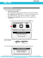
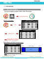
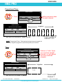
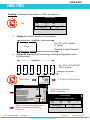
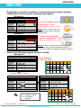
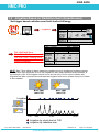
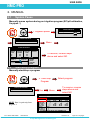
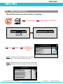
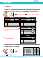
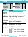
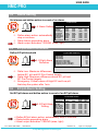
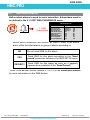
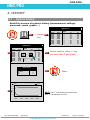
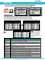
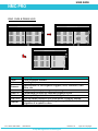
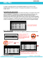
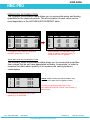
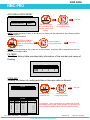
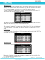
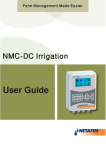
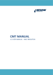
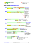
USER GUIDE
NMC-PRO
4. HISTORY
4.1
System History
Read-Only screens of system's history (measurements, settings,
processes, events, graphs…)
SENSORS LOG
Date
11. Sensor
Log
4. History
25/Apr
25/Apr
25/Apr
22/Apr
22/Apr
22/Apr
22/Apr
22/Apr
22/Apr
22/Apr
Time
16:00
15:00
14:00
16:00
16:00
15:00
15:00
14:00
14:00
13:00
Avg.
Hum.
-------------------------------
-EC-
-pH-
3.0
1.4
1.1
1.0
1.0
1.0
1.0
1.0
1.0
1.0
4.1
4.8
5.4
5.1
5.1
5.1
5.1
5.1
5.1
5.1
SENSORS LOG
Time
Avg.
Hum.
---16:00
---15:00
---14:00
---16:00
---16:00
15:00 Help ------15:00
---14:00
---14:00
---13:00
Date
25/Apr
25/Apr
25/Apr
22/Apr
22/Apr
22/Apr
22/Apr
22/Apr
22/Apr
22/Apr
?
-EC3.0
1.4
1.1
1.0
1.0
1.0
Graph
1.0
1.0
1.0
1.0
-pH4.1
4.8
5.4
5.1
5.1
5.1
5.1
5.1
5.1
5.1
Select sensors using +/- key
(no more than 3 per graph)
GRAPH SELECT
Option
Avg. Temp
Avg. Hum.
-EC-pH-
Yes/No
∙
∙
√
√
-EC-
Menu
-pH-
5.0
4.0
3.0
NOTE: Use  arrow keys to zoom in/out.
Use  arrow keys to scroll.
2.0
1.0
16:00
25/04
Doc. Name: NMC-PRO I
16:00
22/04
14:00
22/04
12:00
22/04
09:00
22/04
User Manual
Revision: 02
Crop Management technologies
Page: 33 of 40 pages
USER GUIDE
NMC-PRO
The history menu provides extensive information regarding
measurements and processes performed by the NMC-Pro.
HISTORY
4. History
1.
2.
3.
4.
5.
6.
7.
8.
9.
10.
HISTORY
IRRIGATION LOG
RAD. SUM & DRAIN LOG
UNCOMPLETED IRRIGATION
UNCOMPLETED PROGRAMS
DAILY IRRIGATION
IRRIGATION ACCUMULATION
AUX METER ACCUMULATION
ACCUMULATION RESET
FILTERS
COOLING
4.
5.
6.
7.
8.
9.
10.
11.
12.
13.
UNCOMPLETED PROGRAMS
DAILY IRRIGATION
IRRIGATION ACCUMULATION
AUX METER ACCUMULATION
ACCUMULATION RESET
FILTERS
COOLING
SENSORS LOG
EVENT LOG
SYSTEM LOG
IRRIGATION LOG
The Irrigation Log table includes up to 200 rows of the last irrigations' data.
Each row includes information regarding a specific irrigation.
To view additional information, use the left/right arrow keys.
To switch between dosing quantities or time simply press the ‘+/-‘ key.
DATE : 24-Dec-06
TIME : 17:17:20
IRRIGATION LOG
Date
23/Dec
23/Dec
23/Dec
23/Dec
23/Dec
24/Dec
24/Dec
24/Dec
24/Dec
24/Dec
Time
17:21
17:32
17:42
17:52
18:02
14:50
15;00
15:10
15:20
15:30
V1
255
254
217
115
219
255
254
217
115
219
Reason
Water
Date
Time
3.671
Rad Sum
17:21
23/Dec
0.834
Rad Sum
17:32
23/Dec
4.004
Rad Sum
17:42
23/Dec
2.504
Rad Sum
17:52
23/Dec
0.834
Rad Sum
18:02
23/Dec
3.671
Rad Sum
14:50
24/Dec
0.834
Rad Sum
15;00
24/Dec
4.007
Rad Sum
15:10
24/Dec
2.503
Rad Sum
15:20
24/Dec
0.834
Rad Sum
15:30
24/Dec
DATE : 24-Dec-06
TIME : 17:17:20
IRRIGATION LOG
Date
23/Dec
23/Dec
23/Dec
23/Dec
23/Dec
24/Dec
24/Dec
24/Dec
24/Dec
24/Dec
Item
Date
Time
Valve
Reason
Water
Duration
Flow
Chan. #
EC Low
EC Avg.
EC High
pH Low
pH Avg.
pH High
Doc. Name: NMC-PRO I
DATE : 24-Dec-06
TIME : 17:17:20
IRRIGATION LOG
Time
17:21
17:32
17:42
17:52
18:02
14:50
15;00
15:10
15:20
15:30
V1
255
254
217
115
219
255
254
217
115
219
Chan. 1
3.58
2.63
3.58
3.41
2.64
3.58
2.63
3.57
3.43
3.52
Chan. 2
3.60
2.81
3.59
3.44
2.81
3.59
2.81
3.60
3.44
2.82
V1
255
254
217
115
219
255
254
217
115
219
Duration
00:10:00
00:10:00
00:10:00
00:10:00
00:10:00
00:10:00
00:10:00
00:10:00
00:10:00
00:10:00
Flow
22.000
5.000
24.000
15.000
5.000
22.000
5.000
24.000
15.000
5.000
NOTE: Water quantity is
measured in m³ or gallons;
duration is measured by
time; flow is measured in
m³/h or gallon/m; dosing
quantity is measured in liters
or gallons.
Description
Date in which the irrigation started.
Time in which the irrigation started.
Leading valve; the first valve set for the group of valves
Specification of the irrigation triggers; time, condition, Rad
Sum, etc.
Irrigation quantity (m³ or gallon) or irrigation time.
Irrigation duration (hh:mm:ss).
Average flow throughout the irrigation cycle.
Dosing quantities per channel (liter or gallon) or dosing time.
Lowest EC value recorded during irrigation.
Average EC value recorded during irrigation.
Highest EC value recorded during irrigation.
Lowest pH value recorded during irrigation.
Average pH value recorded during irrigation.
Highest pH value recorded during irrigation.
User Manual
Revision: 02
Crop Management technologies
Page: 34 of 40 pages
USER GUIDE
NMC-PRO
RAD. SUM & DRAIN LOG
DATE : 21-Dec-06
TIME : 14:51:18
RAD. SUM & DRAIN LOG
DATE : 21-Dec-06
TIME : 14:51:33
IRRIGATION LOG
Date
20/Dec
20/Dec
20/Dec
20/Dec
20/Dec
20/Dec
20/Dec
20/Dec
20/Dec
20/Dec
Date
20/Dec
20/Dec
20/Dec
20/Dec
20/Dec
20/Dec
20/Dec
20/Dec
20/Dec
20/Dec
Time
17:26
17:26
17:27
17:27
17:27
17:28
17;28
17:28
17:29
17:29
V1
254
217
115
219
255
254
217
115
219
255
Reason
Rad Sum
Rad Sum
Rad Sum
Rad Sum
Rad Sum
Rad Sum
Rad Sum
Rad Sum
Rad Sum
Rad Sum
Water
1.400
1.400
1.400
1.400
1.400
0.800
0.800
0.800
0.800
0.800
Time
17:26
17:26
17:27
17:27
17:27
17:28
17;28
17:28
17:29
17:29
V1
254
217
115
219
255
254
217
115
219
255
Drain %
100.00
92.86
78.57
100.00
----62.50
100.00
18.75
----100.00
Drain
1450
1300
1100
1400
0
500
800
150
0
850
DATE : 21-Dec-06
TIME : 14:51:45
IRRIGATION LOG
Date
20/Dec
20/Dec
20/Dec
20/Dec
20/Dec
20/Dec
20/Dec
20/Dec
20/Dec
20/Dec
Item
Time
Valve
Reason
Water
Drain %
Drain
Rad Sum
Interval
Doc. Name: NMC-PRO I
Time
17:26
17:26
17:27
17:27
17:27
17:28
17;28
17:28
17:29
17:29
V1
254
217
115
219
255
254
217
115
219
255
Rad Sum
19
19
19
19
19
19
19
19
19
15
Interval
------1
1
2
---------1
1
Description
Time irrigation started.
Leading valve.
Specification of the irrigation triggers; time, condition, Rad
Sum, etc.
Irrigation quantity (m³ or gallon) or irrigation time.
Percentage of drain for relevant irrigation cycle.
Drain quantity related to relevant irrigation.
Accumulated radiation sum level when irrigation started.
Time (in minutes) since last irrigation cycle. Refers to the last
irrigation of a specific valve.
User Manual
Revision: 02
Crop Management technologies
Page: 35 of 40 pages
USER GUIDE
NMC-PRO
UNCOMPLETED IRRIGATION
The Uncompleted Irrigation table provides information of irrigations that were
started but could not be completed due to a failure. To understand why
irrigation was not completed, it is advisable to cross-reference between this
table and the Alarm Definition in section 4.3. The Uncompleted Irrigation table
consists of up to 200 lines. Note that if the letter 'C' appears, it refers to a
program that was triggered by condition program.
UNCOMPLETED IRRIGATION
No.
1
2
Date
20-Dec-06
20-Dec-06
Time
hh:mm
Prog
No.
V1.
No.
Run
No.
Dose
Prog
09:05
09:25
1
2
51+
1
1
1
1
--
Each line includes information regarding when the irrigation
was stopped and added to the uncompleted irrigations table.
Item
Description
Date in which the current line was added to the
Date
uncompleted irrigation table.
Time in which the current line was added to the
Time
uncompleted irrigation table
92- The program that was added to the table was started
manually.
Prog. No.
93- The relevant irrigation was added to the uncompleted
irrigations table for the second time (or more)
consecutively.
Indicates the associated valve. If a group of valves that is
configured to irrigate together is stopped, only the first
Vl. No.
valve is written but a ‘+’ sign is added next to it to indicate
that more valves are associated.
The NMC-Pro will attempt to complete the irrigations from the current day
(until end day time) upon manual or automatic alarm reset.
The valve column of irrigations that are to be completed will be highlighted.
The valve column of irrigations that are currently being completed will
blink.
Run No
Dose Prog.
Prog. Qty.
Left Qty.
Doc. Name: NMC-PRO I
Indicates the associated run time program.
Indicates the associated dosing program.
Planned quantity according to the run time program.
Uncompleted quantity.
User Manual
Revision: 02
Crop Management technologies
Page: 36 of 40 pages
USER GUIDE
NMC-PRO
In order to manually stop an uncompleted irrigation you must go to the
START/STOP VALVE in section 3.3 because the activation is according to
single valves.
UNCOMPLETED PROGRAMS
The Uncompleted Programs table provides information on programs that could
not be completed. It is important to understand the difference between this
table and the Uncompleted Irrigations table; this table consists only of
irrigation cycles that haven’t been started and could not be completed during
the current day. This can happen due to wrong system setup (more tasks than
could be completed), or because the system was not active for a long period
of time, for example due to a power failure, and could not complete its tasks.
UNCOMPLETED PROGRAMS
No.
Date
4
5
6
7
8
9
10
11
12
13
9/Aug
9/Aug
10/Aug
10/Aug
10/Aug
10/Aug
10/Aug
10/Aug
10/Aug
10/Aug
Time
Prog
hh:mm No.
10
20:00
10
21:00
1
04:00
1
05:00
10
06:00
1
07:00
1
09:00
1
11:00
1
13:00
10
14:00
Start
Time
19:00
20:00
13:00
04:00
21:00
05:00
07:00
09:00
11:00
06:00
Prog
Cyc.
1
1
2
2
1
2
2
2
2
1
Left
Cyc.
1
1
2
2
1
2
2
2
2
1
The uncompleted program
table consists of 200 lines.
DAILY IRRIGATION
This table allows you to view history of irrigation quantities or time per valve.
Example: 1 day ago means
you would like to view
yesterday's history, and Today
means you would like to view
the accumulated history since
the last End Day.
DAILY IRRIGATION
How Many Days Ago?
1 Day Ago

Current date viewed at top of screen.
Relevant day
using arrow
keys
ENTER
DATE : 20-Dec-06
DAILY IRRIGATION
Valve
213
214
215
216
217
218
219
220
221
Chan. 1
0.00
0.00
211.36
3.93
30.87
19.06
25.25
0.00
0.00
Chan. 2
0.00
0.00
211.37
3.94
30.82
19.97
26.01
0.00
0.00
Chan. 3
0.00
0.00
211.37
3.94
30.83
18.12
24.49
0.00
0.00
Press +/- to Toggle Quantity/Time
Doc. Name: NMC-PRO I
To open the
selection list
DATE : 20-Dec-06
DAILY IRRIGATION
Valve
213
214
215
216
217
218
219
220
221
Water
0.000
0.000
70.800
1.400
15.900
7.200
13.600
0.000
0.000
Drain%
100
100
11
0
34
45
20
100
100
Dra. Q.
0.000
0.000
8.350
0.000
5.500
3.300
2.850
0.000
0.000
Press +/- to Toggle Quantity/Time
Daily Irrigation table contains all water (m3 or gallon)
and dosing (liter or gallon). To toggle the view
between quantities and time, press the ‘+/-‘ key.
User Manual
Revision: 02
Crop Management technologies
Page: 37 of 40 pages
USER GUIDE
NMC-PRO
IRRIGATION ACCUMULATION
The Irrigation Accumulation table allows you to accumulate water and dosing
quantities for the required periods. The accumulation of each valve can be
reset separately in the ACCUMULATION RESET table.
DATE : 21-Dec-06
IRRIGATION ACCUMULATION
Valve
214
215
216
217
218
219
220
221
222
Date
20-Dec-06
20-Dec-06
20-Dec-06
20-Dec-06
20-Dec-06
20-Dec-06
20-Dec-06
20-Dec-06
20-Dec-06
Water
0.000
70.800
1.400
19.100
7.200
16.800
0.000
0.000
0.000
DATE : 21-Dec-06
IRRIGATION ACCUMULATION
Chan. 1
0.00
211.36
3.93
35.28
19.06
29.65
0.00
0.00
0.00
Press +/- to Toggle Quantity/Time
To toggle the view between quantities
and time, press the ‘+/-‘ key
Valve
214
215
216
217
218
219
220
221
222
Chan. 1
0.00
211.36
3.93
35.28
19.06
29.65
0.00
0.00
0.00
Chan. 2
0.00
211.37
3.94
35.21
19.97
30.38
0.00
0.00
0.00
Chan. 3
0.00
211.37
3.94
35.21
18.12
28.86
0.00
0.00
0.00
Press +/- to Toggle Quantity/Time
Water quantity is measured in cubic
meter or gallons; dosing quantity is
measured in liters or gallons.
AUX METER ACCUMULATION
The Auxiliary Meter Accumulation table allows you to accumulate quantities
from meters that do not have designated software, for example, in order to
measure the drain water quantity or to measure the cooling system’s
consumption.
AUX METER ACCUMULATION
Meter
1
2
3
4
5
6
7
8
Quantity
4.600
3.500
2.200
2.500
3.450
3.600
5.700
4.200
Date
20-Dec-06
20-Dec-06
20-Dec-06
20-Dec-06
20-Dec-06
20-Dec-06
20-Dec-06
20-Dec-06
NOTE: Water meters are accumulators only
and are not a part of the irrigation control.
To reset an auxiliary meter refer to the
ACCUMULATION {XE "Reset Total Quantity" }
table below.
The quantities displayed are in liters
(gallons) up to 9999.999.
Doc. Name: NMC-PRO I
User Manual
Revision: 02
Crop Management technologies
Page: 38 of 40 pages
USER GUIDE
NMC-PRO
ACCUMULATION RESET
ENTER
ACCUMULATION RESET
Reset Valve Quantity For?
Reset Aux. Meter For?
<None>
<None>
ENTER to reset
accumulation of a
specific valve or all
valves
Desired option
using arrow keys
NOTE: When resetting a valve (or all valves), its history will be erased from the following tables:
- Daily Irrigation
- Irrigation Accumulation
ENTER to reset an
individual auxiliary
meter or all auxiliary
meters
Desired option
using arrow keys
ENTER
NOTE: When resetting an Aux meter (or all Aux meters), its history will be erased from the Aux
Meter Accumulation table.
FILTERS
The filters history table provides daily information of the number and cause of
flushing.
FILTERS
Date
10/Aug
9/Aug
8/Aug
Delta P.
0
0
0
Time
44
0
0
Manual
0
0
0
COOLING
Viewing the history of cooling activities or time per valve is allowed.
COOLING
How Many Days Ago?

ENTER
1 Day Ago
ENTER to open
selection list
Prog.
No.
1
2
3
4
5
6
7
8
From
hh:mm
13:10
13:13
--:---:---:---:---:---:--
Doc. Name: NMC-PRO I
COOLING
To
hh:mm
18:14
18:14
--:---:---:---:---:---:--
Relevant day
using arrow keys
Cycles
60
9
-------------------------
For example, 1 day ago means you would like to view
yesterday's history, and Today means you would like to
view the accumulated history since the last End Day.
User Manual
Revision: 02
Crop Management technologies
Page: 39 of 40 pages
USER GUIDE
NMC-PRO
SENSOR LOG
The sensors Log table includes history of average measurements of logged
sensors. In order to define which sensor to log, the user should access menu
6.8 – Sensor Logging, and mark by +/- button the required sensor.
In order to define the measurement interval, the user should go to menu 6.2
and choose the required History resolution.
SENSORS LOG
Date
Time
10/Aug
10/Aug
10/Aug
10/Aug
10/Aug
10/Aug
10/Aug
10/Aug
10/Aug
10/Aug
16:28
16:27
16:26
16:26
16:25
16:24
16:23
16:22
16:21
16:20
Avg.
Hum.
22.7
22.7
22.7
22.7
22.7
22.7
22.7
22.7
22.7
22.7
Temp-1
Temp-2
22.7
22.7
22.7
22.7
22.7
22.7
22.7
22.7
22.7
22.7
-------------------------------
The sensors Log table contains up to 10,000 data fields. Date and time are 2
fields per line and every sensor is an additional field.
For example: logging of 2 sensors uses 4 data fields; 2 for time and date and
1 for each sensor. In this case, the table will consist of a maximum of 2,500
lines.
EVENT LOG
The table provides information of all the processes performed by the NMC-Pro
including their time and date.
EVENT LOG
No.
1
2
3
4
5
6
7
8
9
10
Event
Water Leak # 4
Program # 1 Manual On
Valve #51 Manual Off
Program # 1 Man. Off
Program # 1 Manual On
Valve #51 Low Flow
Program # 1 Man. Off
Program # 2 Rad. On
Valve # 1 High Flow
Program # 2 Rad. Off
Date
20/Dec
20/Dec
20/Dec
20/Dec
20/Dec
20/Dec
20/Dec
20/Dec
20/Dec
20/Dec
Time
09:01
09:03
09:04
09:04
09:04
09:04
09:05
09:21
09:23
09:25
The table consists of the last 999 events.
SYSTEM LOG
This table provides information of all the system changes.
SYSTEM LOG
No.
1
2
3
4
5
6
7
8
9
10
Event
PC Irri. Prog #10 Ch.
Reset Alarm
PC Table #1.3 Change
PC Irri. Prog #1 Ch.
Irrig. Prog #1 Ch.
Irrig. Prog #2 Ch.
Table #7.7 Change
Table #1.3 Change
Table #1.7 Change
Date
20/Dec
20/Dec
20/Dec
20/Dec
20/Dec
20/Dec
20/Dec
20/Dec
20/Dec
20/Dec
Time
09:01
09:03
09:04
09:04
09:04
09:04
09:05
09:21
09:23
09:25
The table consists of the last 999 events.
Examples of system changes are changes of triggered by the controller, the
PC communication, a power off, etc.
Doc. Name: NMC-PRO I
User Manual
Revision: 02
Crop Management technologies
Page: 40 of 40 pages
Doc. Name: NMC-PRO I
User Manual
Revision: 02
Crop Management technologies
Page: 41 of 40 pages