1
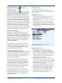
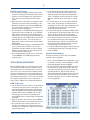
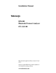
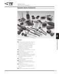
… a step ahead
Application Series
ATM Testing with the
SunSet OCx or SunSet SDH
302 Enzo Drive
San Jose CA 95138 USA
ph 1 408 363 8000
fax 1 408 363 8313
[email protected]
www.sunrisetelecom.com
Publication Number APP-OPT-002 Rev. A
2
INTRODUCTION
Asynchronous Transfer Mode (ATM) is the most widely
deployed backbone technology in the world. ATM grew
out of a need to provide a variety of broadband digital
services over a wide area network (WAN). Today, ATM
carries voice, data, video, and Internet Protocol (IP)
traffic and is the predominant technology for DSL
networks.
Unique among all technologies, ATM guarantees a predefined quality of service (QoS). With its emphasis on
reliability and QoS, ATM requires extensive testing when
installing and turning up connections. Once up, ATM
networks are typically very robust and stable, especially
those running on a SONET/SDH backbone, but periodic
monitoring of ATM traffic and performance is required
to ensure the network is running smoothly.
The test procedures described herein address physical
layer testing, QoS and BER testing, IP-layer testing, and
network monitoring. QoS, BER, and IP testing are most
appropriate for out-of-service testing, such as when
installing an ATM network or when troubleshooting a
network that has failed. Network monitoring is
applicable for live or test traffic.
ATM provides two layers for addressing and switching
based on a Virtual Path Indicator (VPI) and Virtual
Channel Indicator (VCI). In a Virtual Path Connection
(VPC), all ATM cells sharing the same VPI addresses share
the same connection. Within a VPC, the user can
choose between thousands of channels by designating
the VCI of the ATM cell. A Virtual Channel Connection
(VCC), on the other hand, is defined by a VPI/VCI pair
and only applies to that single channel.
In Permanent Virtual Circuits (PVC), connections are
assigned with fixed VPI/VCI values. In a Switched Virtual
Circuits (SVC), VPI/VCI values are reassigned after every
call. The signaling and routing used for SVC circuits is
not addressed in this application note.
VPI/VCI values only have local significance—the VPI/VCI
values are likely to change at each ATM switch. Cells
that start with VPI/VCI of 0/32 may be changed to 8/45,
for example. This presents a challenge to ATM testing—
some knowledge of the routing tables is required to
properly track specific cells at any part in the network.
ATM Cells
ATM uses small, fixed-length cells to facilitate fast
switching through a network. Each cell consists of 5
bytes of header plus 48 bytes of payload.
BACKGROUND
Header: 5 octets
ATM is a connection-orientated technology. The route
through the network is defined before any user data is
sent. In this way, the ATM network can be held to
stringent quality of service and traffic parameters. The
goal of ATM testing is to quantify the quality of the
connection at the physical layer, ATM layer, and higherlayer applications such as IP, whether installing a new
connection or monitoring a live network.
ATM Connections
ATM is defined across an array of physical
carriers including SONET/SDH and T-Carrier/
PDH. The SunSet OCx and SunSet SDH
supports ATM testing from 1.5 Mbps (T1) and
2 Mbps (E1) up to 2.5 Gbps (OC-48, STM-16).
The terminology and testing procedures for
ATM are independent of the physical layer—
only the maximum cell rates differ.
The ATM Cell header contains the VPI, VCI, Payload Type
Indicator (PTI), Cell Loss Priority (CLP), and Header Error
Control (HEC) byte. UNI cells also include a field for
Generic Flow Control (GFC).
The GFC only has local significance and is not carried
end-to-end. In most testing applications, the GFC can
be ignored and simply set to zero.
User-Network Interface (UNI) Header
GFC
ATM defines two types of interfaces: User-toNetwork Interface (UNI) and Network-toNetwork Interface (NNI). NNI applies to traffic between ATM switches and UNI describes the traffic
between an edge device and an ATM switch. Aside from
a slight difference in their headers (see figure to the
right), they are identical for testing purposes.
© 2001 Sunrise Telecom Incorporated
Payload: 48 octets
VPI
VCI
PTI
CLP
HEC
Network-Network Interface (NNI) Header
VCI values from 0 to 31 are used for ATM-layer alarms,
network messaging, and other reserved uses. Though
the VCI can be as high as 65,535, not all ATM switches
ATM Testing with the SunSet OCx or Sunset SDH
3
support all VCI values.
When testing ATM
networks, VCI values
from 32 to 1023 are
best.
Header
Field
Recommended
Value(s)
GFC
0000 (binary)
VPI
0 to 255
once a second, well below the typical bandwidth of user
cells. Alarm Indication Signal (AIS) and Remote Defect
Indicator (RDI) cells are two types of Fault Management
(FM) OAM cells. ATM-layer AIS and RDI defects have
similar definitions to their SONET and SDH counterparts.
VCI
32 to 1023
So long as the VCI
value is 32 or higher,
PTI
000 (binary)
any VPI value can be
CLP
0
used. While NNI can
have a VPI up to
HEC
Set Automatically
4094, UNI can only
support VPI values up to 255. Therefore, it is recommended to use VPI of 255 or less.
OAM cells are designated as F4 (VPC) or F5 (VCC). OAM
cells can also apply to a single segment in the network
or end-to-end. F4 OAM cells are distributed to all VCIs
sharing the same VPI. F5 OAM cells are only delivered
to the specific VPI/VCI indicated. A VCI of 3 (segment)
or 4 (end-to-end) indicates an F4 OAM cell. A PTI of
100 (segment) or 101 (end-to-end) indicates an F5 OAM
cell; F5 OAM cells have a normal VCI value.
The PTI is used to indicate alarms and traffic congestion.
PTI values of 000 or 001 are best for most testing
applications. Advanced users may wish to manually
indicate congestion by setting the PTI to 010 or 011 and
see if the cells are dropped.
When generating OAM cells from your SunSet, use the
ATM Alarm generation function of the set. Do not
create a VCC and manually set the VCI or PTI value to indicate an OAM cell. OAM cells contain special information fields that are not included in a user cell payload.
When the CLP bit is
set to 1, the cell has
a higher probability
to be dropped by a
switch. While useful
for stress testing, it
may not accurately
reflect live traffic;
therefore, setting CLP
to zero is recommended.
OAM Type
Value
Fault
Management
0001
Performance
Management
Function Type
Usage
AIS
Alarm Indication Signal
Value
0000
RDI
Remote Defect Identification
0001
Continuity Check
Continuous monitoring of connections
0100
Cell Loopback
Check connection continuity
1000
Forward Monitoring
On-line performance assessment
0000
Backward Monitoring
On-line performance assessment
0001
Performance Monitoring
Performance Monitoring
0000
Continuity Check
Continuity Check
0001
Group
Group APS
0000
0010
Activation and
Decativation
1000
ATM Protective
Switching
0101
Individual APS
0001
Individual
The HEC byte
provides protection
against bit errors in the cell address field and provides a
mechanism to delineate cells from the physical layer.
O.191 Test Cell
HEC provides no protection for the ATM cell payload. A
ITU-T specification O.191 defines a special cell to test
CRC algorithm generates the HEC value based on the
the QoS of an ATM connection. The O.191 test cell
preceding bytes in the header. This algorithm can
contains a sequence number, timestamp, and CRC field,
correct a single bit error within the 5-byte header; thus,
but no test pattern with which to make a BER measurethese are called correctable HEC errors. A non-correctment. For BER testing, create a user cell with a pseudoable HEC error consists of two or more bit errors in the
random pattern, such as 215-1 (2e15).
address.
OAM Cells
Operation, Administration, and Maintenance (OAM)
cells provide alarms, continuity checks, performance
reports, protection switching, and other messages for
the ATM network. OAM cells are typically only sent
5 octets
4 bits
Header
OAM
Type
4 bits
Function
Type
45 octets
Function
Specific Field
© 2001 Sunrise Telecom Incorporated
6 bits
Future
Use
5 octets
Header
4 bytes
Sequence
Number
4 bytes
37 bytes
Timestamp
1 byte
2 bytes
TCPT
Unused
CRC-16
10 bits
Error Detection Code
ATM Testing with the SunSet OCx or Sunset SDH
4
COMMON TESTING
PITFALLS
ATM Scrambling
To prevent the ATM payload
from resembling
the SONET/SDH framing bytes
(A1, A2), the ATM
payload can be scrambled. Most switches have
scrambling enabled by default. Scrambling does not
affect the cell header and will not impact the ability of
a test set or switch to detect ATM cells. However, user
data sent across an ATM connection with a scrambling
mismatch will become incoherent and useless. Basic
network monitoring is not affected by scrambling, but
other ATM tests, including QoS, BER, and IP testing, will
not function properly. If you are able to receive ATM
cells but unable to make a QoS or BER measurement,
double-check the scrambling setting on both the ATM
equipment and your SunSet. The SunSet’s scrambling
setting is in the ATM Setup or Configuration Menu.
SUNSET SETUP
For a more detailed description of the functions,
options, and measurements of your SunSet, refer to the
User’s Manual.
Configure the test set
1. On the SunSet OCx OC-48 platform or the SunSet
SDH, set the Test Mode to ATM. Then set the
Interface and Payload rates to match the network
being tested.
2. On the SunSet OCx OC-12/3 platform, set the Test
Mode to PT-PT and set the Interface and Payload
rates to match the network being tested. Then, go to
the ATM functions menu to begin transmitting and
receiving ATM cells.
45 Mbps ATM Mapping
Two methods of mapping ATM cells into a 45 Mbps
(DS3) signal are utilized by switches. Physical Layer
Convergence Protocol (PLCP) defined in IEEE 802.6 and
ITU-T G.804 maps the ATM cells into a SONET-like frame
inside the 45 Mbps signal. HEC-based mapping, also
defined in G.804, places the ATM cells directly into the
45 Mbps signal, equivalent to the way ATM cells are
mapped into SONET/SDH.
If the mapping of the test set does not match the
mapping used by the ATM switch, the test set will not
recognize any ATM cells from the switch, and vice-aversa. To change your ATM mapping, go to the ATM
Setup or ATM Configuration menu.
Payload Label Mismatch (PLM)
SONET and SDH specifications indicate that ATM traffic
should use a Payload Label (C2 byte in the path overhead) of 13 (hex). However, not all switches use this
label and the SunSet OCx (OC-12/3) will not send 13
until you enter ATM Functions.
When the C2 bytes do not match, a PLM-P alarm is
declared. The PLM does not interfere with physical
layer measurements, but may prevent an ATM switch
from detecting ATM cells. To prevent a switch from
getting a PLM, you can also change the C2 byte
transmitted from your SunSet. Go to the Send POH
Bytes menu within SONET or SDH Features.
Your SunSet will transmit and receive ATM cells
properly despite a PLM. On your SunSet OCx, you can
disable the PLM measurement or you can change the
expected C2 value by going to your Measurement
Configuration menu.
© 2001 Sunrise Telecom Incorporated
Connect the test set
1. When monitoring a live circuit, be sure to use a
monitor jack, such as on a DSX panel. Optical
networks should have a splitter, such as 90/10, that
passes 90% of the signal through to the network and
allows a test set to access the 10% signal nonintrusively. When monitoring only, do not connect
the transmit jack of the test set.
2. When connecting to a multimode system, use
multimode cables. The receiver on your SunSet OCx/
OC-48 may not be multimode compatible, depending
on which configuration was ordered. Verify with
Sunrise Telecom customer service.
3. If you see a Loss of Signal (LOS) or Loss of Framing
(LOF) when connecting optical equipment, a highpowered transmitter that is saturating the receivers
may be causing it. This is especially true when
connecting the SunSet’s single mode lasers to a
multimode system. In these situations, add an
attenuator, typically -10 dB is adequate.
ATM Testing with the SunSet OCx or Sunset SDH
5
Physical Layer Testing
1. The first step to installing or monitoring any ATM
network is verifying that the physical layer is free of
problems. Errors and defects on the physical layer
are a major cause of problems that affect ATM
traffic.
2. When you connect the SunSet, you should get green
LEDs for the selected interface and framing. If the
PULSES or rate LEDs are green but the FRAME LED is
not, verify that the interface you are connected to
matches the Test Configuration.
3. You should also see the ATM CELL LED light green to
indicate the presence of ATM cells. If the ATM CELL
LED is off, the test set has not been configured for
ATM testing. If you are using a SunSet OCx (OC-12),
you must first go to the ATM Functions menu for the
ATM CELL LED to activate. If you are testing a 45
Mbps or DS3 circuit, verify that you have the proper
ATM mapping.
4. If the LEDs are flashing red, press the HISTORY or LED
key to clear the history condition. Once you are
satisfied that the LEDs indicate no errors or alarms,
(re)start the measurement to clear away any errors
that were detected during setup.
5. Go to the Measurement Results screen. You should
see "NO ERRORS" or "NO ERR" displayed on the
summary screen.
ATM NETWORK MONITORING
When an ATM network is up and running, use the test
set to monitor the ATM cells on the network. Review
the procedure above for connecting the test set to the
circuit. The test set can monitor the network continuously or be programmed to run a test during the peak
usage times. The latter frees a technician from having
to personally monitor the test. The test set can monitor
for a specific length of time, such as 15 minutes or 5
hours, to get a snapshot of the network performance.
4. On the SunSet OCx/OC-48 or SDH, the VCC Scan
screen also shows the utilized or available bandwidth, as selected in the VCC Scan Configuration
screen. In addition, the unit can filter on a specific
VPI value, allowing you to concentrate on a single
VPC.
5. If no traffic appears in the scan and the ATM CELL
LED is green, the circuit may be filled with idle or
unassigned cells. Go to VCC Scan Configuration and
set the VPI Capture field to "ALL" to prevent the
desired VPI from being filtered.
6. If some traffic appears, but important VPI/VCI values
are missing, move the monitoring point closer to the
source, switch by switch, until the cells appear.
Traffic can disappear because network bottlenecks
force switches to drop cells or because a switch has
been configured incorrectly and is sending cells
down the wrong port. The PTI and CLP fields in the
header indicate when ATM connections are experiencing congestion or potential cell loss.
7. If "mystery" VPI/VCI values appear on the traffic scan,
a misconfigured switch may be sending cells with
incorrect VPI/VCI.
Detailed Traffic Analysis
This process monitors a specific VCC for bandwidth
problems, errors, and alarms.
1. Select a specific VPI/VCI from the ATM traffic scan to
be analyzed. Do this by selecting SAVEVCC or SAVE
RX while highlighting the desired VPI/VCI.
2. Go to VCC Statistics and find the VPI/VCI just saved.
Press Detail to see the detailed statistics. Note the
Cell Count and Cell Rate and verify they match the
specified parameters. PVCs and SVCs have predefined maximum and minimum allowable cell rates.
Cells that exceed the limits will be given a CLP of 1
and may be dropped. The test set shows the number
of these tagged cells.
ATM Traffic Scan
1. Use the VCC Scan feature to observe all the channels
currently used in that section of the network. This
process helps identify missing VCCs, monitors total
utilized bandwidth, and can identify misconfigured
switches. Beware that the VPI/VCI value of a VCC
will change at each switch, so knowledge of the
proper VPI/VCI values is vital to properly interpreting
the results.
2. After connecting to the circuit, go to the ATM/IP or
ATM Functions menu & select the VCC Scan feature.
3. The header values are sorted by when they were
detected. The example also shows how a change in
the GFC, PTI, or CLP bits for a single VCC will result in
two (or more) entries.
© 2001 Sunrise Telecom Incorporated
ATM Testing with the SunSet OCx or Sunset SDH
6
3. Congestion is indicative of bandwidth limitations and
may result in cells dropping. To assure good QoS,
monitor the congested cell rate. If too many cells
are congested or tagged, cell loss may occur. By
moving to different switches, you can identify
network bottlenecks and increase bandwidth
accordingly.
4. Verify that the call control settings are correct and
that the source of the ATM traffic is not exceeding
this limit. Cells rates below the minimum are very
disruptive to the services, like video and voice, being
carried over the ATM network. In the case of
Constant Bit Rate (CBR) traffic, it is vital that the
rate is a constant value and never drops or bursts.
5. HEC errors in an ATM system indicate that bit errors
are occurring on the physical layer. Non-correctable
HEC errors result in dropped cells and an increased
cell loss ratio (CLR). The customer’s ATM service
contract will specify maximum CLR and HEC error
rate.
6. You can also see any alarms, such as AIS or RDI, on
the VCC. An AIS is a very serious problem, indicating
a complete lack of service on the VPC (F4) or VCC
(F5). An RDI is a far-end response to an AIS; when you
see an RDI, there is an AIS occurring in the channel’s
opposite direction. Typically, an AIS is due to an LOS,
LOF, or Loss of Pointer (LOP) on the physical layer.
OUT-OF-SERVICE TESTING
The goals of this step are to insert ATM cells, verify that
they are received with no errors, and to test the
bandwidth limitations of the network. The test set will
insert ATM cells into the network and analyze them
upon return. This type of test is typical when installing
ATM switches or turning up a network, though it can
also be used on an in-service network. The procedure
below breaks down the test into several steps. In
practice, these can be done simultaneously with the test
set.
Creating an ATM circuit
1. Before testing, the ATM network administrator must
first establish a PVC through the network and specify
which VPI/VCI are to be used for the test. When
installing new ATM service, the VPI/VCI values will be
the same as specified for the end customer. Otherwise, the administrator will create a PVC specifically
for the test. If the network is also carrying live
traffic, the bandwidth available for testing will be
restricted. If the utilized bandwidth is already 80%
or higher, the test may affect the QoS on the
network as the available bandwidth decreases even
further.
© 2001 Sunrise Telecom Incorporated
2. Most tests use two test sets, one connected at each
end of the PVC. The test can be unidirectional or
bidirectional, but a PVC must be created for each
direction under test.
3. When using a single test set, some type of loopback
is required. A hard loopback uses a cable looped
between the transmitter and receiver so that every
transmitted cell comes back. Hard loopbacks should
not be used for in-service testing and are most
appropriate for testing a single ATM switch. An
alternative method is to specify a PVC that sends the
cells back in the direction of the test set. Because
the PVC only applies to specific address values, this
will not disrupt the network.
VCC Setup
Your Sunset can generate up to 6 or 8 VCCs, but in most
cases, you only need to test one VCC at a time. The
other 5 or 7 VCCs are used for background traffic,
filling up the bandwidth of the connection.
1. Go to VCC Setup and select the first VCC. Input the
VPI/VCI values for the VCC under test. You can set
the received and transmitted header values independently. Again, VCI values 32 and higher are best and
leave the PTI and CLP values 0 unless you want to
simulate congested or tagged cells.
2. In the traffic field, select CBR for most applications.
3. For a new network, start transmitting cells at a 100%
bandwidth. You can do this with a single VCC or a
number of VCCs. If adding a VCC to a live network,
the maximum bandwidth depends on the current
utilization, which you can see on the VCC Scan
screen on page 5. You can then measure the QoS or
BER at each bandwidth. If you discover errors or
poor QoS, incrementally reduce the bandwidth until
the QoS and BER are within acceptable parameters.
4. As your payload, select Pattern for BER testing or
Test Cell for QoS testing. On the SunSet OC-12/3 or
STM-1 black-and-white unit, there is no option for
Test Cell. Instead, select the ALL 0 pattern & activate
the timestamp and sequence number. This is similar
to an O.191 test cell, but lacks the CRC field. For BER
testing, set your pattern to a pseudo-random bit
stream (PRBS) pattern like 223-1, 220-1, or 215-1.
5. Be sure the transmitted and received VCCs are
activated and both the transmitter and receiver are
properly connected to the switch. When you begin
the test, you should have a green ATM CELL LED. If
not, see Physical Layer Testing, above. If problems
occur during QoS and BER testing, verify that both
test sets are set to the same pattern, both have
proper scrambling setting, and they have the same
pattern truncate setting (ATM Setup). In BER testing,
the SunSet should show pattern synchronization
with a green PAT SYNC LED.
ATM Testing with the SunSet OCx or Sunset SDH
7
QoS Testing
The key parameters for QoS testing are Errored Cells and
Cell Error Ratio (CER), Lost Cells and Cell Loss Ratio
(CLR), and Misinserted Cells and Cell Misinsertion Rate
(CMR). Ideally, all these values will be zero.
1. If the CLR is above zero, it may be due to cells being
tagged for not complying with present bandwidth
parameters.
2. Also check the CLR of cells with a CLP of 1.
BER Testing
1. Verify that the test set receives the cells free of bit
errors. Inject a burst of one or more bit errors and
verify the same number of bit errors is received.
2. Inject a specific BER, such as 1x10⁻⁶ (one errored bit
error per million); the test set should receive the
same BER without any added bit errors.
OAM Cells
These tests are most appropriate during installation to
verify proper handling of OAM cells and verify that the
contents of the OAM cells are correct.
1. On the SunSet OCx/OC-48 or SDH, send OAM cells
from the Alarm/Errors menu. On the SunSet OC-12/3
or black-and-white SDH, you must be in the detailed
VCC statistics screen to inject OAM cells.
2. To view the contents of a cell, go to Cell Capture. To
avoid capturing user cells, set the cell type to OAM in
the configuration screen. The SunSet will decode the
header and OAM fields, as applicable, of the captured
cells—simply select the Header or OAM F-keys.
Warning: Sending OAM cells may affect other traffic
on the network.
3. Insert an OAM cell, such as a VP AIS or VC RDI, and
verify that the network element measures and reacts
accordingly. When an ATM switch receives a VP AIS,
it should send a VC AIS downstream and an VP RDI
upstream.
4. Inject a VP or VC loopback cell and verify that the
switch loops it back. Instruct the switch to send a
Performance Management (PM) OAM cell.
COMMON ACRONYMS
AAL
AIS
ATM
APS
BER
CER
CLP
CLR
CDV
CMR
CRC
CTD
DSL
DSX
EDC
FM
GFC
HEC
IP
LCD
LED
LOC
LOF
LOP
LOS
UNI
NNI
OAM
PLM
PRBS
PM
PTI
PVC
QoS
RDI
SDH
SONET
SVC
TCPT
VCC
VCI
VPC
VPI
WAN
ATM Adaptation Layer
Alarm Indication Signal
Asynchronous Transfer Mode
Automatic Protection Switching
Bit Error Rate
Cell Error Ratio
Cell Loss Priority
Cell Loss Ratio
Cell Delay Variation
Cell Misinsertion Rate
Cyclic Redundancy Check
Cell Transit Delay
Digital Subscriber Loop
Digital Signal Cross Connect
Error Detection Code
Fault Management
Generic Flow Control
Header Error Control
Internet Protocol
Loss of Cell Delineation
Light Emitting Diode
Loss of Cell
Loss of Framing
Loss of Pointer
Loss of Signal
User-to-Network Interface
Network-to-Network Interface
Operation, Administration, and Maintenance
Payload Label Mismatch
Pseudo-Random Bit Stream
Performance Management
Payload Type Indicator
Permanent Virtual Circuit
Quality of Service
Remote Defect Indication
Synchronous Digital Hierarchy
Synchronous Optical Network.
Switched Virtual Circuit
Test Cell Payload Type
Virtual Channel Connection
Virtual Channel Indicator
Virtual Path Connection
Virtual Path Indicator
Wide Area Network
Refer to Publication GL-001 for a more extensive list of
ATM terms.
© 2001 Sunrise Telecom Incorporated
ATM Testing with the SunSet OCx or Sunset SDH
… a step ahead