1
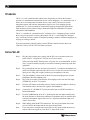
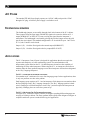
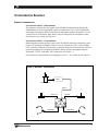
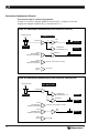
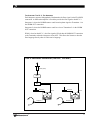
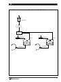
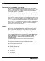
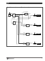
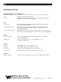
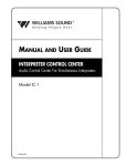
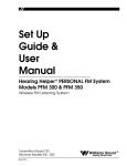
Installation
Guide &
User
Manual
Interpreter Control Center, Model IC–1
Audio Control Center For Simultaneous Interpreters
®
Williams
Sound
Helping People Hear
MAN 067D
2
INTERPRETER CONTROL CENTER, MODEL IC-1
INSTALLATION GUIDE & USER MANUAL
Contents
Page
OVERVIEW
4
INITIAL SETUP
4
AUDIO CONNECTIONS
6
Audio Inputs
Audio Outputs
SWITCHES & CONTROLS
7
AC POWER
8
SWITCHES & CONTROLS
8
CONFIGURATION EXAMPLES
9
Sequential Interpretation
Simultaneous Interpretation
LIMITED WARRANTY
14
SPECIFICATIONS
16
LIST OF ILLUSTRATIONS
Figure 1
IC–1 Signal Flows
5
Figure 2
Sequential Interpretation (Two Lang., Two Interp.)
9
Figure 3a
Simultaneous Interpretation (Floor Language: English)
10
Figure 3b
Simultaneous Interpretation (Floor Language: Non-English)
10
Figure 4
Simultaneous Interpretation (Two Lang., Two Interp.)
10
Figure 5
Simultaneous Interpretation (Three Lang., Two Interp.)
13
Figure 6
Simultaneous Interpretation (Multiple Languages)
15
Williams
Sound ®
Helping People Hear
3
OVERVIEW
The IC-1 is a self-contained audio control center designed to provide all the functions
necessary for simultaneous interpretation of one or more languages. As a stand-alone unit, it
allows one or two interpreters to monitor floor or relay sources, activate one or both
microphone inputs, and route the interpretation signal to one of two language groups.
Additional IC-1's can be cascaded for simultaneous language interpretation applications.
Each interpreter has the option of using a headset/microphone combination or separate
microphones and headphones.
The IC–1 is suitable for “presentation-style” conferences for 1-4 language groups, in which
there is only one presenter at a time at the podium. The IC–1 is not suitable for “delegatestyle” conferences where a number of delegates speaking a number of different languages are
carrying on a dialog or debate.
If you need assistance with this product, contact Williams Sound Customer Service at
1-800-843-3544 or 952-943-2252 for further assistance.
INITIAL SET-UP
Step 1:
Plug the cord from the power supply into the DC power connector on the rear
panel of the IC-1. Plug the AC cord into an AC power outlet.
Spike protection and RF filtering on the AC power line are recommended. In some
cases, a ground isolation plug may be needed to eliminate ground loops with other
equipment.
4
Step 2:
Plug a microphone into the mic input jack on the IC-1. Condenser microphones are
preferred for higher output and lower noise levels. Use the mic switch to select the
input you are using (left or right). Headset-type microphones work best.
Step 3:
Turn the headphone volume controls all the way down and plug stereo or mono
headphones into the headphone jack.
Step 4:
Plug a line-level audio signal from the floor language source into the floor input
(FLOOR IN) on the IC-1 rear panel.
Step 5:
Press the OFF button on the mode selector. Slowly turn the headphone volume up.
You should be able to hear the floor signal in the headphones.
Step 6:
Connect the IC-1 NORM OUT jack to the audio input of an FM Transmitter or
Infrared Modulator.
Step 7:
Press the NORM button on the IC-1. Speaking into the microphone should cause
the audio indicator to flash on the transmitter or modulator and you should be able
to hear the microphone signal with a receiver. Adjust the transmitter input level
control, if necessary.
Step 8:
While talking, hold the MUTE button down. The mic signal should mute in the
receiver. Release the button and the mic signal should return.
Note:
If you experience crosstalk between the floor or relay inputs and the norm or key
outputs, reduce the signal level into the IC-1 inputs at the source.
Williams
Sound ®
Helping People Hear
FIGURE 1: IC-1 SIGNAL FLOWS
OFF
SELECTED
J1
FLOOR
IN
NORM
OUT
MICS
IN
MICS ARE OFF
J2
PHONES
NORM
SELECTED
KEY
OUT
J2
FLOOR
IN
KEY
OUT
MICS
IN
NORM
OUT
MICS
IN
NORM
OUT
MICS
IN
KEY
OUT
PHONES
RELAY
SELECTED
J2
FLOOR
IN
KEY
OUT
RELAY
(KEY)
IN
PHONES
KEY
SELECTED
J1
FLOOR
IN
NORM
OUT
PHONES
Williams
Sound ®
Helping People Hear
5
AUDIO CONNECTIONS
AUDIO INPUTS
MICROPHONE INPUTS
Two microphone inputs are provided for each interpreter to accommodate a wide variety of
microphones. The technician may choose to use either the balanced 1/4" phone jack or the
unbalanced 1/8" mini jack inputs. DC power is supplied for electret microphones on both
inputs. Only one mic input per interpreter should be used. Condenser microphones are
strongly recommended.
FLOOR INPUT
A female XLR jack on the rear panel allows a balanced or unbalanced line-level floor
language signal to be connected directly to the IC-1. The floor signal is selected for
monitoring whenever the OFF, NORM, or KEY modes are selected. This signal will most
likely come from the mixer connected to the microphones used to pick up the presenter’s
voice (podium mic).
RELAY INPUT
A female XLR jack on the rear panel will allow a second balanced or unbalanced line-level
signal to be connected directly to the IC-1. This input is selected for monitoring whenever
the RELAY mode is selected. This signal will most likely come from the normal output
(NORM OUT) of the IC-1 in the translation booth working into a common “key” language.
For example, English is frequently the the “key” language common to all interpreters when
working in the United States.
AUDIO OUTPUTS
HEADPHONE JACKS
Two stereo 1/8" mini phone jacks are provided on the IC-1 front panel. The headphone
output will accommodate mono or stereo, low-impedance (8-32 Ω) earphones or headphones.
NORMAL OUTPUT
A male XLR jack is provided on the rear panel to allow balanced or unbalanced direct
connection to an FM transmitter, infrared transmitter, or tape recorder. When connection to
more than one device is needed, a distribution amplifier may be used. The interpreter’s
microphones are routed to the normal output (NORM OUT) whenever the NORM or
RELAY modes are selected.
KEY OUTPUT
A male XLR jack is provided on the rear panel to allow balanced or unbalanced auxiliary
output. The interpreter’s microphones are routed to the key output (KEY OUT) whenever the
KEY mode is selected. A typical use for the relay output is to allow a team of two
interpreters to feed a second language transmitter. The interpreters change languages by
alternating between NORM and KEY modes.
6
Williams
Sound ®
Helping People Hear
SWITCHES AND CONTROLS
MICROPHONE SWITCH
A 3-way toggle switch on the top panel selects the active microphone. The interpreter can
select left mic, right mic, or left and right mics. LED lights indicate the active microphone.
The LEDs also serve as power on indicators.
MODE SELECTOR SWITCH
Four push buttons on the top panel select the operating mode. See Figure1 for signal flows.
OFF
The floor input (FLOOR IN) is fed to the interpreter’s headsets to allow monitoring of the
meeting. Interpreter’s microphones are muted.
NORM
The floor input (FLOOR IN) is fed to the interpreter’s headsets for interpretation. The
selected interpreter’s microphone is fed to the normal output (NORM OUT).
RELAY
The interpreters are now monitoring the relay input (RELAY or KEY IN) while the selected
microphone feeds the normal output (NORM OUT).
KEY
This mode is used to feed a second language audience. The interpreters are monitoring the
floor input (FLOOR IN) but their microphones are now feeding the key output (KEY OUT).
HEADPHONE VOLUME CONTROLS
Separate volume controls are provided for each headphone output jack. If it is necessary to
set the volume above 5, this indicates the floor or key input signal is too weak. Have a
technician increase the signal level at the source.
MICROPHONE MUTE
Pressing and holding the MIC MUTE switch will interrupt both interpreter’s microphones. It
is typically used as a cough switch. Releasing the button restores the microphone signal.
Williams
Sound ®
Helping People Hear
7
AC POWER
The standard TFP 008 Power Supply operates on 110VAC, 60Hz and provides 12VAC
through a DC plug. A 240VAC power supply is available as well.
FEEDTHROUGH JUMPERS
The feedthrough jumpers are accessible through a hole in the bottom of the IC-1 cabinet.
These jumpers allow the floor input (FLOOR IN) signal to be routed to whichever IC-1
output (NORM OUT or KEY OUT) is not receiving the signal from the interpreter’s
microphone. The feedthrough is activated by placing the provided jumper across the gold
pins on the circuit board. The standard configuration is J1 closed and J2 open. On E-series
IC-1’s, both J1 and J2 can be closed.
Jumper 1 (J1): feeds the floor signal to the normal output (NORM OUT)
Jumper 2 (J2): feeds the floor signal to the key output (RELAY OUT)
APPLICATIONS
The IC–1 Interpreter Control Center is designed for applications that do not require the
expense and complexity of a full conferencing system. The main limitation of an
interpretation system based on the IC–1 is that interpreters do not have the capability of
monitoring all of the other interpreters. When using the IC–1, an interpreter can choose to
monitor either the floor (podium) language or one other interpreter who has been designated
as the “Key” language interpreter.
THE IC–1 IS SUITABLE FOR THE FOLLOWING APPLICATIONS:
“Presentation style” conferences for one to four language groups. In these applications, there
is only one presenter at a time at the podium.
Each language group requires an IC–1 and an interpreter. Each interpreter can monitor either
the floor language or the “Key” language interpreter. The “Key” language position is hardwired. Changing to a different interpreter in the “Key” position requires the interpreters to
physically exchange places or rewire the system set-up.
THE IC–1 IS NOT SUITABLE FOR THE FOLLOWING APPLICATIONS:
“Delegate style” conferences where a number of delegates speaking different languages are
carrying on a dialog or debate. The floor (podium) shifts rapidly from delegate to delegate. A
complete conference system is needed for this type of application.
8
Williams
Sound ®
Helping People Hear
CONFIGURATION EXAMPLES
SEQUENTIAL INTERPRETATION
TWO LANGUAGES: ONE IC-1, ONE INTERPRETER
The interpreter monitors the floor signal via the FLOOR IN connection and chooses the
NORM button to send her microphone signal to Transmitter 1 (TX1) via the NORM OUT
connection. Choosing the KEY button sends her microphone signal to Transmitter 2 (TX2)
via the KEY OUT connection. Since there is only one interpreter, the microphone switch
does not have to be moved. (See Figure 2.)
TWO LANGUAGES: ONE IC-1, TWO INTERPRETERS
Both interpreters monitor the floor signal via the FLOOR IN connection. Interpreter 1 turns
her mic ON and chooses NORM to send her voice to Transmitter 1 (TX1) via the NORM
OUT connection. When the first interpreter is finished, Interpreter 2 moves the mic switch to
turn her microphone ON and chooses the KEY button to send her microphone signal to
Transmitter 2 (TX2) via the KEY OUT connection. (See Figure 2.)
For simultaneous interpretation of two languages, two IC-1’s are needed. See the Figure 4.
FIGURE 2: SEQUENTIAL INTERPRETATION
Mixer
Podium (Floor)
Floor In
Norm Out
Key Out
TX1
TX2
Interpreter 1
Williams
Sound ®
Helping People Hear
Interpreter 2
9
SIMULTANEOUS INTERPRETATION EXAMPLES
TWO LANGUAGES: ONE IC-1, ONE OR TWO INTERPRETERS
In Figure 3a, the floor is English, NORM is selected on IC-1. In Figure 3b, the floor
language has changed to Spanish. Key is selected on the IC-1.
FIGURE 3A: SIMULTANEOUS INTERPRETATION (FLOOR LANGUAGE: ENGLISH)
PODIUM (FLOOR)
NORM SELECTED
FLOOR IN
KEY
OUT
J2
ENGLISH
TX1
ENGLISH
PHONES OUT
INTERPRETER 1 & 2
MIC IN
INTERPRETER 1
(ENGLISH TO SPANISH)
MIC IN
INTERPRETER 2
(SPANISH TO ENGLISH)
RELAY
(KEY) IN
ENGLISH
NORM OUT
SPANISH
TX2
INACTIVE, CAN LISTEN TO FLOOR
NOT USED
FIGURE 3B: SIMULTANEOUS INTERPRETATION (FLOOR LANGUAGE: NON-ENGLISH)
PODIUM (FLOOR)
KEY SELECTED
FLOOR IN
PHONES OUT
INTERPRETER 1 & 2
SPANISH
J1
SPANISH
NORM OUT
SPANISH
TX2
MIC IN
INTERPRETER 1
(ENGLISH TO SPANISH)
INACTIVE, CAN LISTEN TO FLOOR
KEY
OUT
MIC IN
INTERPRETER 2
(SPANISH TO ENGLISH)
RELAY
(KEY) IN
10
ENGLISH
TX1
NOT USED
Williams
Sound ®
Helping People Hear
TWO LANGUAGES: TWO IC-1S, TWO INTERPRETERS
Each Interpreter operates independently. Both monitor the floor signal via the FLOOR IN
connection. A distribution amplifier is needed to provide the floor signal to both IC-1’s.
Interpreter 1 selects the NORM button to send her microphone signal to Transmitter 1 via
the NORM OUT connection.
Interpreter 2 selects the NORM button to send her voice to Transmitter 2 via the NORM
OUT connection.
With J1 closed on both IC-1’s, the floor signal will feed thru the NORM OUT connection
to the Transmitter when the interpreter selects OFF. This allows the listeners to hear the
floor language directly when it is their native language.
FIGURE 4: SIMULTANEOUS INTERPRETATION (TWO LANG., TWO INTERP.)
Podium (Floor)
Mixer
Distribution
Amp
Norm Out
TX1
Interpreter 1
Williams
Sound ®
Helping People Hear
Norm Out
Floor In
Floor In
TX2
Interpreter 2
11
THREE LANGUAGES, TWO IC-1S, TWO INTERPRETERS
This set-up can be used in two ways: (Situation 1) it allows two interpreters to work three
languages when the floor language doesn’t change and both interpreters understand the floor
language, or (Situation 2) when the floor language does change and one of the interpreters
does not understand the floor language, but does understand the other interpreter.
SITUATION 1
Each interpreter operates independently. Both monitor the floor signal via the FLOOR IN
connection. A distribution amplifier is needed to provide the floor signal to each IC-1. The
NORM OUT jack of each IC-1 is connected to a transmitter (TX2 and TX3) to provide
language 2 and language 3.
The KEY OUT connection from each IC-1 is connected to a mixer to allow either interpreter
to provide a relay signal. A distribution amplifier sends the relay signal to the RELAY IN
connection of each IC-2 and to a third transmitter (TX1).
Each interpreter selects the NORM button to send her microphone signal via the NORM
OUT connection to the transmitter for their language. When both interpreters are using the
NORM mode, the floor signal feeds through J2 (if it is closed) to the KEY OUT jacks of
both IC-1s. The signal then feeds to the TX1 through the distribution amplifier. This would
allow listeners to hear the floor signal (language 1) on channel 2 and language 3 on
channel 3.
SITUATION 2
One of the interpreters acts as the “key language” source. The interpreters can take turns
providing the key language if they wish. If Interpreter 1 is going to provide the relay signal,
he or she selects the KEY mode while interpreter 2 selects the RELAY mode. Now
Interpreter 1 will hear the floor signal (language 1) and their microphone will be connected
to the KEY OUT jack, which feeds the RELAY IN jack of the second interpreter’s console
and also Transmitter TX3 through the mixer and distribution amplifiers.
If J1 is closed on Interpreter 1’s console, the floor signal will feed-thru the NORM OUT
connection to the Transmitter TX2.
With Interpreter 2 in the RELAY mode, they will be listening to Interpreter 1 via the RELAY
IN connection. their microphone will be connected to the NORM OUT jack to Transmitter
TX3. J2 should be open on the Interpreter 2’s console. J1 may be closed.
If Interpreter 2 is going to provide the Relay signal, he or she selects the KEY mode on their
console and interpreter 1 selects the RELAY mode on their console.
If you need help with alternate set-ups, contact Williams Sound Customer Service at
1-800-843-3544 or 952-943-2252 for further assistance.
12
Williams
Sound ®
Helping People Hear
FIGURE 5: SIMULTANEOUS INTERPRETATION (THREE LANGUAGES, TWO IC-1S, TWO INTERPRETERS)
Podium (Floor)
Mixer
Distribution
Amp
Norm Out
TX1
Interpreter 1
Williams
Sound ®
Helping People Hear
Norm Out
Floor In
Floor In
TX2
Interpreter 2
13
FOUR LANGUAGES: 4 IC-1S, 4 INTERPRETERS W/RELAY FUNCTION
Each Interpreter operates independently. All monitor the floor signal via the FLOOR IN
connection. A distribution amplifier is needed to provide the floor signal to each IC-1. Each
interpreter selects the NORM button to send her microphone signal via the NORM OUT
connection to the Transmitter for their language .
The “Pivot” person (usually the English interpreter) provides the relay signal via the NORM
OUT connection to a second distribution amplifier. The distribution amplifier sends the relay
signal to the English transmitter and to each of the other interpreters via the RELAY IN
connection on their IC-1.
When the other three interpreters select NORM, they are listening to the original floor signal
and their voice is being sent to their transmitter. When they select RELAY, they are listening
to the pivot interpreter (usually speaking English) and their voice is sent to their transmitter.
With J1 closed on all IC-1’s, the floor signal will feedthru the NORM OUT connection to the
Transmitter when the interpreter selects OFF. This allows the listeners to hear the floor
language directly when it is their native language.
WARRANTY
The Williams Sound IC-1 Interpreter Control Center is engineered and designed to
provide you with many years of reliable service. Williams Sound warrants against
defects in materials and workmanship for FIVE (5) years EXCEPT FOR earphones,
headphones, cables and all other accessory products. Accessory products carry a
90 day warranty.
If the product fails within the specified warranty period, Williams Sound will determine
whether to repair or replace the defective equipment. This warranty does not apply
to physical damage, abuse, mis-use, or products that have been modified. This
warranty does not apply to damage caused by attempting to charge nonrechargeable batteries.
If you experience difficulty with your system, call for Customer Assistance:
1-800-843-3544.
If it is necessary to return the system for service, a Williams Sound representative will
give you a Return Authorization Number (RA) and shipping instructions.
Pack the system carefully and send it to:
Williams Sound Corp.
10321 West 70th Street
Eden Prairie, MN 55344-3459 USA
Phone: 800-843-3544
952-943-2252
Fax:
952-943-2174
TTY:
952-943-9675
e-mail: [email protected]
14
Williams
Sound ®
Helping People Hear
FIGURE 6: SIMULTANEOUS INTERPRETATION (MULTIPLE LANGUAGES)
Key Language
Floor In
Floor
Signal
IC-1
Norm Out
ENGLISH
DA 1
TX1
Podium (Floor)
Relay Signal
DA2
Floor In
IC-1
Norm Out
Floor In
IC-1
Norm Out
Floor In
IC-1
Williams
Sound ®
Helping People Hear
FRENCH
TX3
Relay In
Relay In
SPANISH
TX2
Relay In
Norm Out
GERMAN
TX4
15
SYSTEM SPECIFICATIONS
INTERPRETER CONTROL CENTER, MODEL IC–1
Dimensions, Weight:
7" (17.7 cm) W x 5.625" (14.3 cm) D x 3.125" (9.3 cm) H, 1.82 lbs. (.83 kg)
Color:
Beige epoxy paint with black legends
Power:
External power supply, 12 VAC, 50 or 60 Hz, 10 VA, (TFP 008 Power Supply)
(A 240 VAC Power Supply is also available)
INPUTS
Floor In, Key In:
3-Pin XLR female jack, balanced or unbalanced line-level, Max 3.8 Vrms,
Gain 6 dB, 43 kΩ input impedance
1/4" Microphone Inputs:
Left and right, 1/4" TRS phone jack, balanced or unbalanced mic-level,
Max 70 mVrms, Gain 46 dB, Supplies simplex DC power for electret mics,
1.75 kΩ input impedance
3.5 mm Microphone Inputs:
Left and right, 3.5 mm TRS phone jack, unbalanced (T,S) for condenser mics,
Max 70 mVrms, Gain 46 dB, Supplies DC power on tip, 1.75 kΩ input impedance
OUTPUTS
Key Out, Norm Out:
3-Pin XLR male jack, balanced or unbalanced line-level, 7.7 Max Vrms,
56 Ω source impedance
Headphones:
3.5 mm TRS phone jack, mono or stereo headphone, 8-32 Ω,
63.7 mW at 8 Ω load max
CONTROLS
Volume:
Left and right, rotary, controls headset volume
Mic Switch:
3–way toggle. Selects left mic, right mic, or both
Mute Switch:
Push button. Mutes left and right mics when depressed
Function Switch:
4-way push button. Selects OFF, NORM, RELAY, or KEY modes
CONTROLS
Feedthru Jumpers:
Located on bottom of cabinet. Used to select floor signal feedthru options.
Williams Sound Corp.
10321 West 70th St., Eden Prairie, MN 55344-3459
U.S.A. 800-843-3544 / 952-943-2252 / FAX: 952-943-2174
© 2003, Williams Sound Corp.
MAN 067D