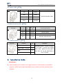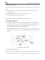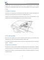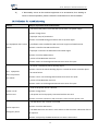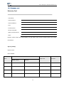
1
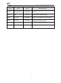
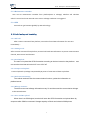
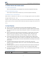
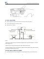
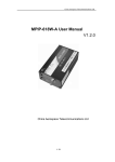
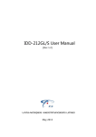
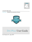
MPIP-619 User Manual REV2.0.3 China Aerospace Telecommunications Ltd China Aerospace Telecommunications Ltd Contents Contents ................................................................................................................................................ 1 Version information........................................................................................................................... 2 Scope of application......................................................................................................................... 4 1、Product introduction................................................................................................................... 4 2、Disclaimer....................................................................................................................................... 4 3、Packing list and the optional accessories ......................................................................... 5 3.1 Terminal standard configuration list ......................................................................... 5 3.2 Optional accessories ......................................................................................................... 5 4、Special words................................................................................................................................. 5 4.1 position data....................................................................................................................... 5 4.2 SMS command........................................................................................................................... 6 4.3 Security key......................................................................................................................... 6 4.4 User phone number............................................................................................................... 6 4.5 Platform service................................................................................................................. 6 5、Terminal product features......................................................................................................... 6 5.1 Special functions............................................................................................................... 6 5.1.1 Intelligent power save ................................................................................................ 6 5.1.2 Positioning ................................................................................................................... 6 5.1.3 Maintenance reminder ............................................................................................... 7 5.1.4 GPS .............................................................................................................................. 7 5.2 Positioning and tracking ................................................................................................. 7 5.2.1 Roll call ........................................................................................................................... 7 5.2.2 Timing track.................................................................................................................... 7 5.2.3 Fixed Upload .................................................................................................................. 7 5.2.4 Compressed upload ....................................................................................................... 7 5.2.5 Real-time monitoring ..................................................................................................... 7 5.2.6 Mileage statistics............................................................................................................ 7 5.2.7 Store and Re-upload ...................................................................................................... 7 5.3 Status detection and function control ....................................................................... 8 5.3.1 Vehicle status detection................................................................................................. 8 5.3.2 Read vehicle battery voltage.......................................................................................... 8 5.3.3 Remote cut-off electric &restore ................................................................................ 8 5.4 Alarm functions................................................................................................................... 8 5.4.1 Terminal alarm type ....................................................................................................... 8 5.4.2 HT-196 alarm type...................................................................................................... 9 5.4.3 SMS alarm reminder ................................................................................................ 10 6、Setting guidance......................................................................................................................... 10 6.1 SMS parameters setting ................................................................................................... 10 6.2 Castelecom PCTools ......................................................................................................... 10 6.3 Platform parameters setting ......................................................................................... 10 7、SMS functions............................................................................................................................... 10 7.1 Phone location................................................................................................................... 10 1 China Aerospace Telecommunications Ltd 7.2 SMS location....................................................................................................................... 10 7.3 Alarm SMS alert (have set the user phone numbers) ............................................. 11 7.3.1 Remote cut-off electric &restore .............................................................................. 11 7.3.2 Restart .......................................................................................................................... 11 7.3.3 SMS parameters setting ............................................................................................... 11 8、Technical specification & interface introduction ......................................................... 13 8.1 Technical specification ................................................................................................. 13 8.2 Power cable(4PIN) ......................................................................................................... 14 8.3 Multi-function cable(4PIN)............................................................................................. 14 8.4 G-Mouse interface(4PIN)................................................................................................... 14 9、Installation Guide..................................................................................................................... 14 9.1 SIM card installation ............................................................................................................ 15 9.2 Placement of main unit ................................................................................................... 15 9.3 Installation of GSM antenna............................................................................................... 15 9.4 G-Mouse installation ........................................................................................................... 16 9.5 HT-196R installation ............................................................................................................ 16 9.6 SOS button installation ....................................................................................................... 16 9.7 Relay installation........................................................................................................... 17 9.8 Power cable and ACC cable connect ............................................................................. 17 9.9 Finish installation ......................................................................................................... 18 9.13 Status................................................................................................................................. 18 9.13.1 led indicator ............................................................................................................... 18 9.13.2 HT-196 beep ........................................................................................................... 19 10、Maintenance................................................................................................................................. 20 10.1 Maintenance instructions ............................................................................................. 20 10.2 Solution for troubleshooting ..................................................................................... 21 10.3 Warranty card................................................................................................................... 23 11、Claim ............................................................................................................................................ 24 Version information 2 China Aerospace Telecommunications Ltd version editor Modified clause date V1.0.0 Kang kuan ming 2014.08.06 Artificial V1.0.1 Didi V2.0.1 Liu yunfei 2015.02.06 Modify the led indicator status description V2.0.3 Liu yunfei 2015.09.21 Modify the relay connect way and description Modify the GSM indicator color 2014.8.7 And the power cable description 3 China Aerospace Telecommunications Ltd Scope of application This user manual is applicable to MPIP-619 vehicle terminal product。 1、Product introduction MPIP-619 in-vehicle terminal integrates internationally leading technologies of GPS, GSM, intelligent automatic control and anti-theft alarming. It is able to monitor the position, safety, operation and technical status of the moving target 24 hours a day, and it can provide you real-time tracking, fleet management, anti-theft of vehicle, asking for help in case of accident, fault repair, data checking, fuel consumption statistics, mileage statistics, maintenance reminder, driving behavior analyzer, RFID attendance statistics, SMS alarm, Geo-fence alarm, easy installation, read the total fuel consumption, read the fault alarm, read the engine speed alarm and temperature alarm, etc. Note: some function shall be required to purchase some accessories 2、Disclaimer MPIP-619 in-vehicle terminal is developed based on the GPS applied technology of the United States. Since its GPS receiver must always keep direct communication with the satellite in the course of operation, the equipment may be affected when it operates in electromagnetic shielded areas or when the carrier (such as a vehicle) is under some shelters like indoors, in the underground parking lot or under a footbridge. MPIP-619 in-vehicle terminal is a RF communication equipment. The product shall be kept as far away as possible from areas that might lead to explosion like fuel warehouses, chemical plants, and so on. The product may be affected in places sensitive to external radio-frequency signals, such as gas stations, hospitals, schools, where radio frequency suppressors may be installed. Because data communication is conducted between the system adopting GSM technology and the monitoring center, user must make sure the SIM card support GPRS data traffic offered by 4 China Aerospace Telecommunications Ltd the public communication network operators. Besides, the SIM card shall always contain sufficient fee. Please do not use SIM cards subject to limitations of regions; 3、Packing list and the optional accessories 3.1 Terminal standard configuration list Name Quantity unit Description Main unit 1 PCS GPS terminal Power cable 1 PCS GPS terminal power cable GPS MOUSE 1 PCS GPS MOUSE Multi-function cable 1 PCS GPS terminal multifunction cable Installation kit 1 set Including fuse, Velcro, cable tie 3.2 Optional accessories Name Quantity unit Description USB setting cable 1 PCS CASTELECOM PC Tools setting cable SOS button 1 PCS SOS button Relay 1 PCS 12V or 24V optional,remote electric cut-off Driving behavior, inbuilt GPS, GPS. functions: acceleration/deceleration/quick lane changing/sharp HT-196R 1 PCS turn/ collision,buzzer and light instructions, RFID(optional), alternative between G-mouse and HT-196R 4、Special words 4.1 position data the datagram including “location, alarm, status” which the terminal send to the platform. 5 China Aerospace Telecommunications Ltd 4.2 SMS command Send to device SIM card number including the read and setting parameters .(the device SIM card should have SMS function) 4.3 Security key The key is the legality of the SMS command validation. The length of the key is fixed 6 characters,default is last 6 number of the device serial number(can modify).Please get more details from platform operator. 4.4 User phone number For receiving the SOS alarm ,low battery voltage alarm, power-off alarm. 4.5 Platform service Platform service providers ( Platform) paid for the computer automation and artificial service, convenient for users to get vehicle information such as location, alarm, status. The service content and the charges agreed jointly by the providers and users. 5、Terminal product features 5.1 Special functions 5.1.1 Intelligent power save Device supports none power-save mode and half power-save mode. After ACC turns off for 5 minutes, device will upload the last available location. At the same time, device will disconnect GPRS, stop supplying power to all peripheral unit and set GSM module to standby. After device falls asleep, it will be woke up by: ACC on, door open, engine cut off, SOS alarm, , called. Then it will register GSM network and supply power to peripheral unit. Once device log in platform, it will upload above alarm, including the latest available GPS location. At the same time, device will start upload regularly as preset time interval until next ACC off. Terminal default mode is half power-save ,you can set the mode by Castelecom PCTOOLS. 5.1.2 Positioning Call the device “user number” or SMS to device user number, After receives command from platform, terminal will send GPS information for one time immediately 6 China Aerospace Telecommunications Ltd 5.1.3 Maintenance reminder User can set maintenance reminder from platform(time or mileage). Platform will calculate vehicle’s record and issue reminder once time or mileage condition are triggered. 5.1.4 GPS Terminal can get locations globally by GPS technology。 5.2 Positioning and tracking 5.2.1 Roll call After receives command from platform, terminal will send GPS information for one time immediately.。 5.2.2 Timing track After receives command from platform, terminal will send GPS information as preset communication channel, time interval and duration. 5.2.3 Fixed Upload The main unit upload the GPS information according to the time interval to the platform,user can sent the time interval under ACC on or ACC off. 5.2.4 Compressed upload Terminal uploads a package compressed by 8 pieces of time-interval data to platform. 5.2.5 Real-time monitoring The vehicle terminal have the communication function, update the information to platform/server. 5.2.6 Mileage statistics The device can read mileage information every 5s and then send the accumulative mileage to the server/server. 5.2.7 Store and Re-upload When there’s no GSM signal, terminal will store the GPS information and upload them by sequence after GSM is connected. Storage capacity of blind area’s data is 3000 pieces. 7 China Aerospace Telecommunications Ltd 5.3 Status detection and function control 5.3.1 Vehicle status detection Device can detect ignition on/off, peripheral units connection and upload the abnormity. 5.3.2 Read vehicle battery voltage Device acquires vehicle’s battery condition every 2 seconds and upload the abnormity. 5.3.3 Remote cut-off electric &restore When vehicle is confirmed to be stolen, user can cut off engine ignition system from platform through 12V/24V relay. Vice versa. Remark: in order to guarantee the safety, if you sent the cut-off command when ACC is ON, engine ignition system can only be cuted-off when the 619 device detect ACC change of the state from off to on。 5.4 Alarm functions User can set whether to enable alarm and set the alarm thresholds by the platform. When the device trigger the alarm, alarm information will upload to platform within location data, the alarm status in the location data will always be “effective” until the platform confirm the alarm. When the terminal have received the alarm acknowledge. The alarm status in the location data no need to set as” effective” including door open/close alarm, SOS alarm ,ACC ON/OFF, acceleration, deceleration, quick lane changing、sharp turn, collision alarm. These alarms including idle engine, GPS fault alarm, temperature alarm ,fatigue driving alarm,, high speeding ,power cable cut-off alarm, low voltage alarm, when the platform have confirmed them, the alarm status in the location data should be set according to the real-time vehicle status. The platform should response the device’s alarm. If the device don’t receive the response ,the device will repeat 3 times ,every 1 minute. but the high speed and high RPM only report I times. All alarms trigger once ,upload once. After upload, the device alarm status automatically be cleared,(before the alarm status do not return to normal, can’t trigger the alarm again). The device will send the SOS alarm max 5 times , every 1 minute when the device don’t get the platform’s response. 5.4.1 Terminal alarm type Alarm type description 8 China Aerospace Telecommunications Ltd SOS Low voltage alarm Power failure (power cable cut-off alarm) GPS failure It will trigger SOS alarm when user presses SOS button for more than 3 seconds. Terminal automatic detect the external power supply, trigger when the external voltage is less than 10.5V (12 v model) or 21V (24v model), default setting is enable In-built backup battery,trigger when the external voltage is less than 8V and automatic switch to backup battery supply, default setting is enable Trigger when the G-mouse or HT-196 failure ,or trigger when don’t receive the GPS information in 2 minutes, default setting is enable Trigger when the vehicle speed is more than the preset threshold for 60 seconds, Speed alarm default setting is enable, speed threshold is 120Km/h, detecting time is 60 seconds(0-300 seconds optional) ACC on/off ACC ON trigger when the ACC status changed from off to on, last 2 seconds, on the contrary, trigger the ACC OFF alarm. default setting is close Trigger when the continuous driving time is more than the preset threshold, the fatigue driving alarm information include the continuous driving time and the threshold. default setting is close. idle engine Geo-fence alarm Route offset alarm Trigger when the idle time is more than preset threshold , default setting is close. Trigger when the vehicle enter or exit the preset area, can set by the platform: rectangle circle ,polygon area( up t0 64 area), supplied by the platform The terminal upload the positioning data, the platform automatically determine whether conform to the default preset route on the platform. supplied by the platform. The terminal upload the positioning data, the platform automatically determine Road speed limit whether conform to the default preset road speed limit on the platform. supplied by the platform. 5.4.2 HT-196 alarm type Alarm type collision Sharp turn Accelerate Decelerate quick lane changing Description built-in G –sensor 3 axis acceleration sensor chip,when over the alarm threshold, the device will send alarm to platform. built-in G –sensor 3 axis acceleration sensor chip,when over the alarm threshold, the device will send alarm to platform. built-in G –sensor 3 axis acceleration sensor chip,when over the alarm threshold, the device will send alarm to platform. built-in G –sensor 3 axis acceleration sensor chip,when over the alarm threshold, the device will send alarm to platform. built-in G –sensor 3 axis acceleration sensor chip,when over the alarm threshold, the device will send alarm to platform. 9 China Aerospace Telecommunications Ltd 5.4.3 SMS alarm reminder Device sends SMS to user phone number when alarm occurs, including SOS alarm, power supply off alarm, low voltage alarm and vehicle trouble. 6、Setting guidance Terminal parameters can be set by Castelecom PCTools, platform and SMS. 6.1 SMS parameters setting Any mobile number can send the SMS command to the terminal SIM card number to read and set terminal parameters. 6.2 Castelecom PCTools Please download the castelecom PCtools from the website: http://www.castelecom.com/pc-tools 6.3 Platform parameters setting Terminal have connected the platform, please get the account and password from platform operators. Then you can read and set the parameters. The platform website : http://www.freelivetrack.com/ 7、SMS functions 7.1 Phone location Dial the SIM card number in device and hang up the call (in 6 seconds) before it is caught, then device will send a message with location information to initiator. User can check location on map by clicking the linkage in message. Example:A12345,xx,yy,A/V!http://maps.google.com/?q=22.7643750,114.3974383 xx:CSQ value,yy:number of valid GPS stars,A / V:A=valid location,V=void location. 7.2 SMS location Send a SMS command ”security key,LBG” to the device SIM card number through any phone number, Device will reply a location SMS to the sender phone. The location SMS includes Google map link. example:A12345,xx,yy,A/V!http://maps.google.com/?q=22.7643750,114.3974383 10 China Aerospace Telecommunications Ltd 7.3 Alarm SMS alert (have set the user phone numbers) When the device trigger the low voltage alarm, SOS, power failure alarm, the terminal SIM card number will send the alarm SMS to the user phone numbers. Example: 12345,low voltage, xx,yy,A/V!http://maps.google.com/?q=38.870941,-77.056114 12345,power failure,xx,yy,A/V!http://maps.google.com/?q=38.870941,-77.056114 12345,SOS,xx,yy,A/V!http://maps.google.com/?q=38.870941,-77.056114 7.3.1 Remote cut-off electric &restore Send a SMS command to the device SIM card number through any phone number, Device will be cut off/restore the ignition system. SMS command format: Remote engine off:”security key,Engine off” Remote engine on:”security key,Engine on” The function can be achieved through the platform, the use of remote l cut-off, please contact the service providers or distributor for technical support to ensure the safety. 7.3.2 Restart Send a SMS command “security key,restart” to the device SIM card number through any phone number, Device will restart. Reply: restart,ok. If unsuccessful execution, there is no any reply. 7.3.3 SMS parameters setting Set language Can send SMS command “security key,EN/CN” to set the language of device. EN is English. CN is Chinese. For example: SMS command: 123456,EN Reply: EN,ok Set user phone number Send SMS command “security key,SP,no1,no2,no3” to the number in device through a ny phone.When some position phone is not needed to set, pls write nothing in this po sition.Specially, send SMS “security key, SP” to clear all of user phone numbers For example: SMS command: 123456,SP,13600000001,, Reply: SP,13600000001,,,ok 11 China Aerospace Telecommunications Ltd SMS command: 123456,SP Reply: SP,ok Set GPRS parameters Send SMS command “SMS security key,SG,DialMode,IP/Domain,Port,APN,user,passwor d” to the number in device through any phone. DialMode =0, express domain mode =1, express IP mode For example: SMS command: 123456,SG,0,www.freelivetrack.com,16190,cmnet,, Reply: SG,ok. 12 China Aerospace Telecommunications Ltd 8、Technical specification & interface introduction 8.1 Technical specification Item description Dimension 75mm (L)*48mm (W)*20mm (H) Weight 80g IP rate IP54 Shape Aluminum alloy Working Voltage DC9V~36V Battery 3.7V/500mAH Lithium battery Standby current 40mA Normal working current ≤[email protected](no including accessory) Max working current ≤[email protected](no including accessory) Current when data ≤150 [email protected](no including accessory) transmission Current when ACC OFF Power saving mode(sleep ≤90mA@12V/24V(no including accessory) ≤20mA@12V/24V(no including accessory) mode) Working environment -30℃~+70℃,relative humidity 5%~95%(Not frosting) Storage environment -40℃~+85℃,relative humidity 5%~95%(Not frosting) Communication GPRS(Quad-band:GSM 850/900/1800/1900MHz) Position GPS Sensitivity:-159dB,positional accuracy ≤15m,speed accuracy GPS ≤0.1m/s Certification FCC / CE / E-Mark HT-196R(optional) RFID attendance and driving behavior , RFID frequency 125KHz Note: Above current value is acquired by testing of 12V power supply with good network signal, the actual current may be different according to local circumstance 13 China Aerospace Telecommunications Ltd 8.2 Power cable(4PIN) overview function PIN color TXD 1 Brown GND 2 Black DC(9~36V) 3 Red RXD 4 Orange Function description Connect the power cable 8.3 Multi-function cable(4PIN) overview Pin mark Pin Pin cable color Function description ACC 1 Gray ACC detection CUT 2 purple Control output1, GND 3 Blue GND SOS 4 white SOS input signal detection 8.4 G-Mouse interface(4PIN) overview Function Pin Remarks TXD 1 DC5V output(1A max) 2 GND 3 RXD 4 Standard RS232,connect G-mouse or HT-196R。if connect the configur ation cable,please exit the serial m ode after you set the parameters by the PCTOOLS 9、Installation Guide !WARNING: below operation are for reference, we suggest the device to be installed by professional engineer. CASTEL will not take responsibility for any vehicle circuit fault caused by user’s operation. 14 China Aerospace Telecommunications Ltd 9.1 SIM card installation Insert the SIM card before installation of the main unit. The installation processes of SIM card are below: Open the side plate of the main unit with screw driver (make sure the switch to “off” before inserting the SIM card); Insert the SIM card to the card seat, then put the switch to “ON” side. Fix the side plate to the main unit, fasten the screw. Notice:please make sure the SIM card have SMS and GPRS function. 9.2 Placement of main unit The location for placement of main unit should be determined in advance. The location should allow secure installation, concealment, anti-humidity, avoidance of high-temperature area, and be far away from magnetic field, air bag, sound system, ABS system and other sensitive electronic equipment. In addition, it should be installed snugly。 Recommended installation location: the concealed position inside the decorated board under the dashboard or under the seat. Refer to the following diagram for the specific installation location: recommended installation location 9.3 Installation of GSM antenna GSM antenna is installed at a concealed place inside the vehicle but the place should not be closed too much. Generally it is placed inside the decorated plate under the steering wheel or at the 15 China Aerospace Telecommunications Ltd included angle inside the decorated plate under the front or rear windshield to ensure smooth transmission of communication signals. Refer to the following diagram for the specific installation location: 9.4 G-Mouse installation G-mouse can’t be installed under metal baffle plate which will hinder the receipt of GPS signal, thus affecting the normal monitoring and positioning of the MPIP-619 main unit. G-mouse is generally placed inside the decorated plate under the front or rear windshield or on the dashboard. Refer to the following diagram for the specific installation location: 9.5 HT-196R installation Please don’t put HT-196R under any metal or explosion prevention metal, user can attach it to the windshield or fix it under the windshield by double face adhesive tape. Driving behavior analyzer should be kept horizontal, and the angle with ground shall not exceed 15 degrees inclination. 9.6 SOS button installation The SOS button should be placed between the dashboard and the steering wheel to facilitate operation of the driver. The SOS button has adhesive tape stuck to its back. User can remove the adhesive tape and attach it to the intended position. Refer to the following diagram for the specific installation location: 16 China Aerospace Telecommunications Ltd 9.7 Relay installation Connect the CUT1 control line of the multi-function cable with relay’s 86 pin. Connect the relay 85 with car battery anode, 87a.30 connect ,as below: Notice: 1,please don’t install this relay in the flameout magnetic valve in the diesel engines,or vehicle power supply circuit. 2,please connect correctly the terminal ACC cable with the vehicle ACC; 3,the above diagram is only for your reference. Please chose the proper mode of the connection according to the different vehicle circuit. 9.8 Power cable and ACC cable connect In principle should not cut the original circuit loop except the Relay cut-off cable connect. 17 China Aerospace Telecommunications Ltd Please make sure the main unit is insulated with the vehicle metal parts, power cable ,SOS button or other cable should properly connect the battery positive/negative. The power cord fuse must be connected. The terminal ACC detection cable should be connected to the vehicle ACC port, otherwise, the remote cut-off electric operation maybe be invalid, there is a hidden safe trouble. 9.9 Finish installation After all equipment is installed, please insert the fuse into the fuse seat and power on the main unit Meanwhile please start the vehicle to check if equipment works normally. Upon finds any abnormality, please turn off the main unit immediately and recheck all installation of wires or send it to a professional vehicle service center to check. Log on the platform to check if the vehicle is normally online and the positioning is proper. If there are problems, please refer to the User Manual for trouble shooting. Finally, please contact the local dealer if the problems cannot be solved. 9.13 Status 9.13.1 led indicator Type Color Power( on the device) RED Definition of status remark Fixed on:working normally Off:power off Off: sleep mode or no power GSM(on the device) Blue Flashing: Registered successfully On: Registering Off: sleep mode or no power GPS(on the device) green Flashing: GPS located On: search GPS information Off: sleep mode or no power GSM (SOS button) red GPS (G-Mouse) green Flashing: Registered successfully On the SOS button On: Registering Off: sleep mode or no power G-MOUSE Flashing: GPS located 18 China Aerospace Telecommunications Ltd On: search GPS information Red on: search GPS information GPS (HT-196) Red,yellow&green Green on: GPS 3D located HT-196 Yellow on: GPS 2D located Off: sleep mode or no power Flashing(on 250ms, off 250ms):No ID card or illegal ID card RFID (HT-196) On 1s: Searching for ID card Yellow HT-196 Constantly on: ID card detected Off: power off within power on 1 minutes, or RFID power supply abnormity Yellow on 3s:General undesirable driving Driving Behavior (HT-196) behavior Yellow &Red Red on3s: Serious undesirable driving behavior off: No undesirable driving behavior 9.13.2 HT-196 beep Description remark power on Di (last 500ms) read RFID card Di (last 500ms) illegal card Di- Di (last 100ms interval 200ms) no card reminder Di- Di (last 100ms interval 1s) general undesirable driving behavior serious undesirable driving behavior Di- Di -Di(last 100ms interval 100ms) Di- Di -Di -Di-Di (last 100ms interval 100ms) High RPM Di- Di -Di(last 100ms interval 100ms) High speed Di- Di -Di(last 100ms interval 100ms) Fatigue alarm Di- Di -Di(last 100ms interval 100ms) Idle engine Di- Di -Di(last 100ms interval 100ms) 19 HT-196 China Aerospace Telecommunications Ltd 10、Maintenance 10.1 Maintenance instructions 1) The voltage range of normal power supply for terminal is DC 9V—36V, and the recommended operating voltage is 12V or 24V. Prior to installation, user shall make sure if the power supply falls within the range aforesaid. 2) When the in-Vehicle terminal is powered on, do not plug in or pullout the antenna or remove SIM card to avoid damage to the in-Vehicle terminal and SIM card. 3) The connection socket of the in-Vehicle terminal shall avoid direct contact with conductive body, otherwise it may result in short circuit and danger. 4) Do not use the in-Vehicle terminal in an environment where there is much dust. When washing the vehicle, try to prevent the terminal from being soaked or showered to avoid damage to the terminal. 5) Keep using the in-Vehicle terminal in normal temperature. The equipment may be damaged when operating for long in an environment where the temperature is above 85℃ or lower than -40℃. 6) When the vehicle is inside building, tunnel or within a shielded area, receiving of GPS signals and GSM communication network signals will be affected. After the vehicle moves out of the area mentioned above, receiving of GPS signals and GSM network will automatically resume. 7) The main unit has built-in spare battery which will not be activated and begin working until the equipment is used for the first time and supplied with external power. After the battery is activated, when the external power supply is cut off, the equipment will automatically switch to operate with power supply from the built-in battery, and the operation can last for about 10 hours (calculated based on that the terminal data transmits once every 5 minutes). 8) The terminal equipment can use the accessories designated or recognized by CASTEL only. Unauthorized accessories may damage the terminal equipment. 20 China Aerospace Telecommunications Ltd 9) If abnormality occurs to the terminal equipment or its accessories, thus leading to failure of normal operation, please contact the manufacturer or the local dealer. 10.2 Solution for troubleshooting Failure Analysis of possible causes and solutions 1. The fuse of the power cord is burned so that there is no power supply. Solution: change fuses. 2. Improper setup of parameters Solution: check APN setting parameters and set up them again. The equipment won’t come 3. Insufficient value installed for SIM card onion-support of GPRS function. online Solution: reconfirm the SIM card function. 4. Improper connection of GSM antenna and weak signal. Solution: check the GSM antenna. 5. Failure of the MPIP-619 main unit Solution: send it to the designated maintenance center for repair. 1. G-mouse is shielded by metal shielding object. Solution: remove the metal shielding object or reinstall G-mouse at another place. The equipment 2. G-mouse failure. does not position Solution: return it to the designated maintenance center for repair. the vehicle 3. Failure of the MPIP-619 main unit. Solution: send it to the designated maintenance center for repair. 1. Fuse of the power source is burned. Power cut-off Solution: change fuses. alarm occurs 2. The power cord is improperly connected with the ACC end. Solution: check the connection and reconnect it tithe common power cord. 1. The SOS button has not been connected. Solution: check the SOS button. Fail to report the 2. The MPIP-619 main unit won’t come online so that the alarm information fails to emergency alarm be reported. Solution: analyze why the MPIP-619 main unit won’t come online. 21 China Aerospace Telecommunications Ltd 3. Failure of the MPIP-619 main unit Solution: send it to the designated maintenance center for repair. 22 China Aerospace Telecommunications Ltd 10.3 Warranty card Warranty Card User Name: Contact Phone: Contact Address: Post: Purchase time: Device series NO.: Agency and phone No.: Note: Remark: Please keep this card properly for get better after service. Details please see below information. Agency (stamp): Repair record Device Model: Reason and status record Date Repair man Repair reason Record 23 Customer China Aerospace Telecommunications Ltd Note: Agency should fill this card completely when repair. 11、Claim Without written authorization of CHINA AEROSPACE TELECOMMUNICATIONS LTD. , any kind of copy, transmission, dispatching or saving of this file is prohibited. CHINA AEROSPACE TELECOMMUNICATIONS LTD. keeps the rights of reservation and modification without any notification in advance. Receiving and operation time would be affected by SIM card, network and using circumstance of different device. And we don’t take responsibility of data losing and income wastage, or any special, occasion, indirect reason. This file is based on “local” situation. In spite of relative law, explicit or hinting data including(but no limited in) hinting selling data, is no connection with accuracy and reliability. Copy right reserved CHINA AEROSPACE TELECOMMUNICATION SLTD. Unit710-711, 7/F, East Wing, No. 10ScienceParkWestAvenue, Science Park, Shatin, New Territories, Hong Kong 24