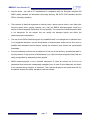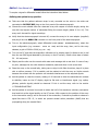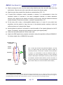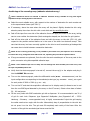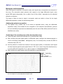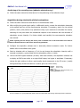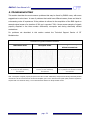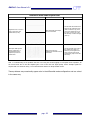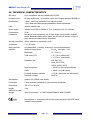
1
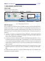
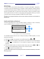
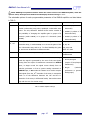
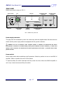
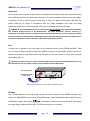
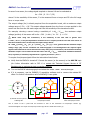
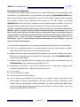
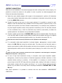
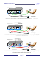
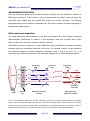
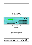
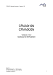
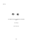
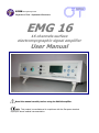
LISiN Bioengineering Center Polytechnic of Turin – Department of Electronics EMG 16 16 channels surface electromyographic signal amplifier User Manual Read this manual carefully before using the EMG16 amplifier. This product is manufactured in compliance with the European standard 93/42/CEE about medical instrumentation. EMG 16 User Manual v3.1 INDEX 1. GENERAL DESCRIPTION ...................................................................................... pag. 3 2. EMG 16 KIT CONTENT .......................................................................................... pag. 3 3. END USERS ........................................................................................................... pag. 3 CONTRAINDICATIONS .................................................................................... pag. 3 SIDE EFFECTS ................................................................................................ pag. 3 4. WARNINGS ........................................................................................................... pag. 4 5. SYMBOLS USED ON EMG 16 AND IN THE USER MANUAL .................................. pag. 6 6. TECHNICAL SPECIFICATIONS .............................................................................. pag. 6 7. PRELIMINARY INSTRUCTIONS ............................................................................ pag. 9 FRONT PANEL AUX IN connector .................................................................................. pag. ARRAY IN connector .............................................................................. pag. PATIENT REF plug ................................................................................ pag. DRL IN plug ......................................................................................... pag. DRL OUT plug ...................................................................................... pag. Liquid crystal display and keyboard ........................................................ pag. REAR PANEL Power supply connector ......................................................................... pag. Power supply switch .............................................................................. pag. Fuses box ............................................................................................. pag. Fan ....................................................................................................... pag. ID label................................................................................................. pag. RS232 connector .................................................................................. pag. ACQUISITION BUS connector ................................................................. pag. BLANKING INPUT connector .................................................................. pag. TRIGGER INPUT connector .................................................................... pag. 9 10 10 10 11 11 13 13 14 14 14 15 15 15 15 8. USE OF THE ELECTROMYOGRAPH ....................................................................... pag. 16 ELECROMIOGRAPH SETUP ........................................................................ pag. 16 ACCESSORIES CONNECTION ...................................................................... pag. 17 Force/Torque sensors ........................................................................... pag. Articular goniometer ............................................................................. pag. General purpose analog input ................................................................ pag. Neuromuscular stimulator ..................................................................... pag. 17 19 19 20 PATIENT CONNECTION .............................................................................. pag. 22 MEASUREMENT EXECUTION ...................................................................... pag. 24 Differential mode acquisition ................................................................. pag. 24 Monopolar mode acquisition .................................................................. pag. 31 Acquisition during electrically elicited contractions .................................. pag. 32 9. TROUBLESHOOTING ............................................................................................ pag. 34 10. EMG16 MAINTENANCE AND STORAGE .............................................................. pag. 40 11. TECHNICAL CHARACTERISTICS ......................................................................... pag. 41 12. WARRANTY ........................................................................................................ pag. 42 WARRANTY CONDITIONS ............................................................................... pag. 42 pag. 2 EMG 16 User Manual v3.1 1. GENERAL DESCRIPTION EMG16 is a 16 channels surface elecromyogram (EMG) amplifier, which accepts input voltages detected by surface EMG electrodes and provides a set of output voltages that are an amplified, conditioned and filtered version of the input voltages. EMG16 allows the acquisition of signals generated by muscles during voluntary or electrically elicited contractions recorded by surface electrode arrays system in different configurations (one 16-electrodes array, two 8-electrodes arrays, four 4-electrodes arrays). This device assures the complete safety for the patient and considerably reduces interference signals (in particular 50~60 Hz line interference). Moreover, it allows the connection of optional devices such as force/torque meters or articular goniometers to perform joint biomechanical and electromyographic measures. For optimal signal acquisition we suggest the use of the software package EMGACQ or EMGACQ II, developed at LISiN, Bioengineering Center , Polytechnic of Turin, Italy. 2. EMG 16 KIT CONTENT n° 1 EMG 16 surface EMG amplifier; n° 1 cable adapter with a 16 electrodes array for EMG signal detection; n° 1 conductive gel package; n° 1 EMG 16 user manual. 3. END USER EMG 16 electromyograph is a medical device developed and designed for therapists and trainers for outpatient treatment use. EMG16 surface EMG amplifier allows the non invasive detection of the electromyographic signal (EMG) generated during voluntary or electrically elicited muscular contractions, recorded using surface electrode arrays placed over the skin, aligned in the direction of muscle fibers. Contraindications EMG16 has no particular contraindications related to its joint use with neuromuscular stimulators or personal computers provided that all the electrical devices connected with it and the electrical power distribution system are in compliance with the relative safety rules and standards (in particular, proper connection to ground is required). Side effects pag. 3 EMG 16 User Manual v3.1 No significant side effects are known. All the materials used for the manufacturing of the parts of that could be in contact with patient are biocompatible; possible allergic cutaneous reactions (e.g. skin reddening) are reduced to the minimum, also because of the short duration of the electromyographic signal acquisition. 4. WARNINGS The use is forbidden with electro surgery equipment, with short waves or microwaves therapy devices. The use is forbidden to mentally incompetent people. The use is forbidden to people who suffer from sensitivity disorders. The use is forbidden to temporarily disabled people if not assisted by qualified staff (e.g. medical doctor or therapist). The use is forbidden in presence of deterioration or damage of the equipment itself. The use is forbidden near inflammable substances or in ambient at high oxygen concentration. Consult a doctor before use in case of osteosynthesis metal devices on patient. Use electrodes supplied by manufacturer only; EMG16 is tested and guaranteed if used with the suggested electrode type. In case of permeation of extraneous matters into the device contact immediately the reseller or the manufacturer. In case of fall verify that there is no presence of fissures, crack or any kind of damage on the box or contact the reseller or the manufacturer. EMG16 is subject to environmental disturbances (e.g. electrostatic or electromagnetic interference generated by electrical equipment or other sources) that are not dangerous for the patient: they can only affect the estimate of the physiological variables extracted from the EMG signal. These parameters are not used to make a diagnosis so they are not dangerous for the patient at all. Before performing a measure it is necessary to verify the quality of the ground connections because the use of medical devices with electrical outlet without ground represents an high risk for the user. Verify that multiple outlets and extension cords, if used, do not interrupt the ground connection. Power up the EMG16 and the data acquisition PC using only Power supply connectors connected with an insulation transformer. The connection between EMG16 and other electrical devices (e.g. a PC) must comply with the European standard EN 60601-1-1 on medical devices. pag. 4 EMG 16 User Manual v3.1 Use the device only with a PC manufactured in compliance with the European standards EN 60950 (safety standard for information technology devices), EN 55022 (EMC standard) and EN 55024 (immunity standard). The presence of electrical equipment or devices (relay, remote control switch, neon lights with incorrect power factor, paging systems, etc.) near the EMG16 electromyograph could be a source of electromagnetic interference for the amplifier. The presence of electromagnetic fields is not dangerous for the subject but can modify the detected signals and affect the electromyographic estimations. The use of the EMG16 electromyograph by unqualified staff is not dangerous for patients but it is not suggested because a correct interpretation of measurement results can be done only by qualified and adequately trained people, having the necessary basic clinical and physiological knowledge. Incorrect estimates could be the consequence of the use of the device by unauthorized staff or by the presence of high sources of disturbances (e.g. high level electromagnetic fields) that are easily recognizable by adequately trained people. EMG16 electromyograph is not a portable equipment. It could be moved, but it has to be guaranteed that the device is adequately packaged (even in case of short distances) and that it is not exposed during transport to vibrations. This could be dangerous and could cause risk for the patient because the safety standards could be violated. pag. 5 EMG 16 User Manual v3.1 5. SYMBOLS USED ON EMG16 AND IN THE USER MANUAL Product manufactured in compliance with the European standard 93/42/CEE on medical instrumentation. Class BF for circuitry applied to patient. Read carefully the instruction notes before use. Dangerous voltage level, device supplied with line voltage. Multifunction keys to select the parameter to be modified. Multifunction keys to modify the selected parameter value. Multifunction key to enter the selected parameter value. Signals input. Signals output. I O Power on (I): switch on power line voltage supply. Power off (O): switch off power line voltage supply. 6. TECHNICAL SPECIFICATIONS EMG16 surface EMG amplifier is an optically and galvanically insulated device to guarantee a high level of safety to patient and user in all the operating conditions, separating the part of the circuitry connected to patient from the circuitry that could be connected to external non medical devices. The EMG16 electromyograph can be used to detect surface EMG signals in monopolar or in single differential mode (suitable in presence of high level interference), during voluntary or electrically elicited contractions. An embedded common mode voltage reduction circuit can be used to reduce interference in monopolar mode acquisition (see section 8). Surface EMG signals can be detected using different array configurations, as reported below in TAB.1 Array electrode number Number of probes that can be used simultaneously 16 electrodes 1 probe 8 electrodes 2 probes 4 electrodes 4 probes TAB. 1: Connection modalities for the detection probes on EMG16 As shown, it is possible to acquire signals simultaneously from two or four different probes: this can be useful in case of investigation on different muscles at the same time. pag. 6 EMG 16 User Manual v3.1 Using the front panel keyboard or the acquisition software EMGACQ II, it is possible to choose the number of probes and assign a gain value to each; when the signals are detected from different muscles (e.g. biceps brachii or upper trapezius) it can be necessary to set a different gain level for each probe, in order to have best quality recorded signals and exploit the full range of the A/D converter. EMG16 technical specifications are shown in TAB. 2 below: EMG channels Maximum input range 20 mVPP @ Gain = 100 Bandwidth 10 ÷ 500 Hz, 4 order Bessel band pass filter Total noise (RTI) < 0.7 VRMS (differential), < 1.0 VRMS (monopolar) Selectable gain 100, 200, 500; 1000, 2000, 5000; 10000, 20000, 50000 Input impedance > 90 M on the entire bandwidth CMRR > 96 dB (103 dB typical) Crosstalk between channels < -75 dB (monopolar and differential) Insulation voltage 4000 VDC th Auxiliary channel – Mode: torque / force Load cells supply voltage 5 VDC Gain 300 (both channel A and B) Bandwidth 0 ÷ 65 Hz Output voltage* Vu = 300 [ (S1 5V F1 / FS1) + (S2 5V F2 / FS2) ] Output voltage range -5V ÷ 5V Torque / force offset removal** -2V ÷ 2V, software controlled Auxiliary channel – Mode: angle / analog input Maximum input range - 5V ÷ 5 V Gain 1 Bandwidth 0 ÷ 65 Hz, 4 order Bessel band pass filter Maximum output range - 5V ÷ 5 V th * Example: using a couple of sensors with a sensitivity S = 1 mV Full Range / V supply each of them gives a full range output of 1 mV / Vsupply 5 = 5 mV (-5 mV for negative range). If each sensors are at full range the output voltage ill be Vu = 300 [ 5 mV + 5 mV ] = 3V. Output voltage range is -3V ÷ 3V. ** In previous example offset removal has a range 2V / 3V 100 67 % F.R. ; it will be able to null an offset up to the 67% of the full output range. TAB. 2: EMG16 technical specification pag. 7 EMG 16 User Manual v3.1 7. PRELIMINARY INSTRUCTIONS FRONT PANEL EMG16 front panel is shown in FIG. 1: AUX IN connector ARRAY IN connector AUX IN ARRAY IN DRL IN plug DRL OUT plug DRL IN COMMON MODE REJECTION DRL OUT OK LISiN R PATIENT REF EMG 16 BIOENGINEERING CENTER 16 CHANNELS SURFACE EMG ACQUISITION SYSTEM PATIENT REF plug Liquid crystal display Keyboard FIG. 1: EMG16 amplifier front panel view AUX IN Connector AUX IN connector can be used to connect an articular goniometer, a generic analog signal with a maximum input range of -5V +5V or a couple of non preamplified force/torque sensors (a pre amplifier stage is included into EMG16). Sampling frequency and resolution is the same used in the EMG channels (set by acquisition software and acquisition board) and signals are acquired on channel 16. To acquire, on channel 16, a signal from an articular goniometer / generic analog input, the mode: CH16: Angle must be selected on the display. In this mode, the signal on AUX IN is sent to channel 16 without any amplification. To acquire on channel 16 a signal from a couple of preamplified force/torque sensor, it has to be selected on the display the mode: CH16: Force/Torque. In this mode, the output signal of two external force/torque transducers collected on the AUX IN input are summed and the resultant signal is amplified and sent to channel 16 of the amplifier, after compensating the DC offset by software. To acquire on channel 16 an EMG signal (this make sense only in monopolar mode or in single differential mode with a circular array) it has to be selected on the display the mode: CH16: EMG. For detailed information about how to change the EMG16 settings refer to the paragraph Liquid crystal display and keyboard subsection. pag. 8 EMG 16 User Manual v3.1 NOTE: for technical information about the use of the AUX IN connector with other external transducers contact the Technical Support Service of OT Bioelttronica. pag. 9 EMG 16 User Manual v3.1 ARRAY IN connector ARRAY IN is used to connect a 16 electrodes array adapter (mode: Probes: 1x16CH), a double adapter for two 8 electrodes arrays (mode: Probes: 2x8CH) or a quadruple adapter for four 4 electrodes arrays (mode: Probes: 4x4CH). The Probes mode has to be selected corresponding to the selected array adapter. For detailed information about how to change the EMG16 settings refer to Liquid crystal display and keyboard subsection. Each adapter can be connected to both a standard silver bar electrodes array (suitable to find the best position to place the array on the muscle and to perform short time isometric measurements) and an adhesive array (suitable for long term signal acquisition and/or during dynamic contractions). NOTE: for correct signal recordings is always necessary to connect the patient ground to the PATIENT REF plug using a strap fixed on a point where there is no electromyographic activity (e.g. the ankle or the wrist). In monopolar mode acquisitions (Mode: Monopolar) is necessary to connect another ground strap to DRL IN plug and, in case of high level interference, a third one to DRL OUT plug. For further information refer to DRL IN plug and DRL OUT plug subsections. PATIENT REF plug This plug is always used to connect a point without electromyographic activity (e.g. the ankle or the wrist) of the patient to the EMG16 as patient ground, using the supplied ground strap. The strap has to be wet with water to assure a good electric contact with the patient. NOTE: lack of this connection prevents the correct acquisition of the EMG signal. DRL IN plug This input should be used primarily during acquisition in monopolar mode (Mode: Monopolar): a ground strap must be connected to this plug with the supplied cable . The strap must be wet with water to assure a good electric contact with the patient and must be fixed on a point without electromyographic activity (e.g. the ankle or the wrist) next to the strap used for patient grounding. NOTE: lack of this connection prevents the correct acquisition of the EMG signal in monopolar mode (Mode: Monopolar). pag. 10 EMG 16 User Manual v3.1 DRL OUT plug This output must be used primarily during acquisition in monopolar mode (Mode: Monopolar), in presence of high level interference due, for example, to electric equipment, isokinetic machines or other electrical devices working in EMG16 proximity. A ground strap has to be connected to this plug with the supplied cable. The strap must be wet with water to assure a good electric contact with the patient and has to be fixed on a point without electromyographic activity (e.g. the ankle or the wrist) next to the straps connected to PATIENT REF and DRL IN plugs. NOTE: in case of high level interference, the lack of this connection prevents the correct acquisition of the EMG signal. Liquid crystal display and keyboard The liquid crystal display turns on when the EMG16 amplifier is switched on. After an introducing screen, the EMG16 settings are presented on a screen as indicated in FIG. 2: Probes: 4x4CH G1: G3: 500 100 G2: 5k G4: 20k OK Mode: Differential CH16: Force/Torque FIG. 2: Example of a screen on the liquid crystal display The embedded keyboard allows the user to change the settings of EMG16 amplifier; to do that follow these instructions: Move the arrow () on the parameter to be modified using the keys Press and . to confirm the selection of the parameter to be modified; the arrow will be displayed in negative ( ) to indicate that it is now possible to change the value of the selected parameter. Scroll the available options and select the desired value using the keys and ; the parameter will be changed directly to allow the user to monitor the effect. Press to accept the new parameter value. NOTE: display’s ligh is turned on by any key pressure and it is turned off automatically 5 second after the last key pressure. pag. 11 EMG 16 User Manual v3.1 NOTE: EMGACQ II acquisition software allows the remote control of the EMG16 amplifier; when this option is active, the keyboard is disabled and the display shows the string PC-Link. The selectable options for each programmable parameter of the EMG16 amplifier are listed below in TAB. 3: Parameter Probes Description Available options EMG input probes configuration: 16 electrodes array probe, 1x16CH (1 probe of 16 double 8 electrodes array probe, quadruple 4 electrodes array electrodes) probe. The only difference between these modes consists in 2x8CH (2 probes of 8 the possibility of changing the amplifier gain in groups of 8 electrodes each) channels (mode 2x8CH) or in groups of 4 channels (mode 4x4CH (4 probes of 4 4x4CH). electrodes each) G1, G2, Probe gain: in mode 1x16CH, G1 is the gain of the 16 100, 200, 500 G3, G4 electrodes array, in mode 2x8CH, G1 e G2 are the gains of the 1k, 2k, 5k two 8 electrodes array and so on. To allow flexibility the gains 10k, 20k, 50k Mode G1 and G2 can be different in different modes. NOTE: 1k=1000 Acquisition mode: monopolar or single differential (bipolar) Monopolar Differential CH16 Select the source for EMG16 channel 16. In Force/Torque EMG mode the signal is generated by the sum of the two signals Force/Torque coming from the couple of transducers connected on AUX IN (couple of force/torque input; in Angle mode the signal comes directly from an transducers) articular goniometer or from a generic analog connected on Angle AUX IN input; in EMG mode the channel 16 is used to acquire goniometer or generic EMG signal (from the 16th electrode of the array in monopolar analog input) mode or as the difference between the 16th and the 1st electrode of the array in differential mode, that makes sense only with the use of a circular array). TAB. 3: EMG16 amplifier settings pag. 12 (articular EMG 16 User Manual v3.1 REAR PANEL EMG16 rear panel is shown in FIG. 3: Power switch Fan BLANKING INPUT ID label connector 0 1 Fuses box BLANKING INPUT Power supply connector RS232 ACQUISITION BUS RS232 ACQUISITION BUS connector TRIGGER INPUT connector TRIGGER INPUT connector FIG. 3: EMG16 rear panel view Power supply connector This plug must be connected to power line socket only with the supplied cable. Be aware that the socket and the power supply cable are equipped with the ground conductor. DANGER: the use of extension cords, multiple sockets or adapters can deteriorate the device performances. Connection to sockets lacking in the ground conductor (“earth” conductor) or with a bad quality of this connection can deteriorate the device performances and cause a potential risk for both patient and user. Power switch Power supply switch allows switching on/off operations. Switch to position I to turn on the EMG 16 amplifier; switch to position O to turn off the device. To improve safety the switch interrupts both the power line wires. When the EMG16 amplifier is not in use, it has to be turned off by this switch. pag. 13 EMG 16 User Manual v3.1 Fuses box On the same panel of power supply switch and power line connector there is an extractable fuses box containing one fuse for each power line wire. In normal conditions fuses have to be integer; breakdown of one or both the fuses occurs only in case of a device break down, therefore the device could be no longer in compliance with the safety standards even after the fuses replacement with other of the same type. Fuse type is reported on the rear ID label. DANGER: in case of breakdown of one or both the fuses do not replace them but contact immediately the Technical Support Service of OT Bioelettronica. The fuses breakdown could be caused by a malfunction that could represent a potential risk for the patient and the user, and it is necessary to detect it before restarting to use the device. Replacing the fuses with other fuse types can be very dangerous for the patient and the user. Remove the power cable before opening the fuse box. Fan A cooling fan is placed on the rear panel for the internal circuitry of the EMG16 amplifier. Take care to leave at least 8cm space behind the EMG16 to ensure an appropriate air flow and do not obstruct the slots on the lower panel and the grid on the rear panel to let air flow to avoid overheating (FIG. 4). NOTE: block of the air flow can cause overheating and device break down. Verify that the fan is free to spin and that there is no presence of dust or other substances that could block it. Hot air flow (fan) Cold air flow (lower panel slots) > 8 cm FIG. 4 flow and minimum required space behind the device ID label The ID label placed on the rear panel reports the serial number of the EMG16 amplifier (see section 12. WARRANTY to be sent to OT Bioelettronica), some identification data required by law, certification number and symbol , manufacturer address and some technical information as power supply range and fuse type. This label must never be removed. pag. 14 EMG 16 User Manual v3.1 RS232 connector This connector is reserved for assistance operations. It must not be used. NOTE: connecting other devices to EMG16 through this connector can cause damages to the device. ACQUISITION BUS connector This is a SCSI-II type connector used to connect, with the supplied cable, the data acquisition card in PCI (National Instruments PCI6045E) or PCMCIA format (National Instruments DAQ6045E) supplied with the EMG16 amplifier. NOTE: the use of acquisition boards different from that supplied with the electromyograph can cause malfunctions and damages to the acquisition board and to the amplifier. For further information about the use of other possible acquisition systems contact the Technical Support Service of OT Bioelettronica. BLANKING INPUT connector This BNC type connector is used to connect the EMG16 amplifier to a compatible neuromuscular stimulator, to allow EMG signal acquisition during electrically elicited contractions. This input works with digital TTL compatible signals (0÷5V), coming from the stimulator, that drives the internal blanking circuitry. When the BLANKING signal is active (5V), the amplifier stages are inhibited to prevent saturation and transients caused by the stimulation pulse. NOTE: for further information about the joint use of the electromyograph with neuromuscular stimulators and for logic signal compatibility contact the Technical Support Service of OT Bioelettronica. TRIGGER INPUT connector This BNC type connector is used to connect the electromyograph with a compatible neuromuscular stimulator, to allow EMG signal acquisition during electrically elicited contractions. This input accepts a digital TTL compatible signal (0÷5V), coming from the stimulator, that is sent to the acquisition board to allow the acquisition software to synchronize the PC screen refresh with the stimulation pulse (through the rising edge of the TRIGGER signal) and to acquire properly the EMG signal. Minimal duration of the trigger pulse is 100 s. NOTE: for further information about the joint use of the electromyograph with neuromuscular stimulators and for logic signal compatibility contact the Technical Support Service of OT Bioelettronica. pag. 15 EMG 16 User Manual v3.1 8. USE OF THE ELECTROMYOGRAPH ELECTROMYOGRAPH SETUP Before performing a data acquisition it is necessary to setup all the instrumentation; this operation has to be done keeping the equipment turned off. Take care to connect all the cables properly into the respective plugs and sockets. To setup correctly the electromyograph follow these instructions (FIG. 5): Make sure that the computer that will be used with the electromyograph is turned off. Make sure that the EMG16 power on switch is set in “O” position. Connect the ACQUISITION BUS connector, placed on the EMG16 rear panel, to the acquisition board, using the flat cable provided, taking care to insert it properly. If the acquisition board is a PCMCIA card (suitable for notebooks), connect the flat cable provided to the board taking care to insert it properly, then insert the card into the first free PCMCIA slot of your notebook. If the acquisition board is a PCI board (suitable for desktop computers), contact the Technical Support Service of OT Bioelettronica for installation troubleshooting; when the PCI card has been correctly installed, connect the flat cable to the acquisition board taking care to insert it properly. Connect the EMG16 power supply connector, placed on the rear panel, to a 90÷260 VAC, 50÷60 Hz power line supply voltage using the provided cable. DANGER: the use of extension cords, multiple sockets or adapters can deteriorate the device performances. Connection to sockets lacking in the ground conductor (“earth” conductor) or with a bad quality of this connection can deteriorate the device performances and cause a potential risk for patient and user. Turn on the PC (desktop computer or notebook). Install the acquisition software following the instructions reported on the provided user manual. Computer with an installed acquisition board Electromyograph Power line socket Power supply cable Flat cable FIG. 5: Standard setup of the electromyograph pag. 16 EMG 16 User Manual v3.1 NOTE: when the instrumentation is turned off, always turn off firstly the electromyograph and than the PC. Shutting down the PC before the electromyograph has been turned off can cause damages to the acquisition board and to the electromyograph. To connect accessories (biomechanical measurement instruments, force/torque transducers, neuromuscular stimulators), refer to the subsections hereinafter. ACCESSORIES CONNECTION It is possible to interface EMG16 with external devices as neuromuscular stimulators or biomechanical measurements instrumentation to detect, for example, the EMG signal during electrically elicited contractions or to measure the articular force/torque during a voluntary contraction. Subsections hereinafter show how to use the electromyograph in these conditions and how to connect EMG16 to external devices. Force/Torque sensors During EMG signal acquisition in single differential mode, using a linear 16 electrodes array, the channel 16 of the electromyograph has no sense as EMG channel1, so it is possible to use this channel to acquire a signal coming from a couple of force/torque sensors (transducer input impedance < 100kΩ). The electromyograph contains two amplifiers that can be connected to a load cell (or torsiometer) each, whose output signals are summed together to obtain the final force/torque signal. This way it is possible to measure the total force/torque also using instruments equipped with two sensors. A DC offset compensation circuitry, EMGACQ II software controlled, can be used to compensate a residual force/torque (due for example to the weight of the limb). For further information about this option refer to EMGACQ II user guide. Of course, it is possible to acquire the signal coming from just one transducer, sending to the second input a zero signal. In case of two sensors, the voltage signal acquired on channel 16 can be evaluated as follows: Vu = 300 [ (S1 5V F1 / FS1) + (S2 5V F2 / FS2) ] where S1 and S2 are the sensors sensitivity, expressed as VFS/VSUPPLY (full range generated voltage for each volt of the load cell supply voltage), F1 and F2 are the generated forces or toques and FS1 and FS2 are the full range forces or torques for each sensor. Each cell is supplied with a voltage of 5VDC. This is not true when using a circular array as well as in the case of EMG rectal and urethral probes. In that case the channel 16 represents the single differential signal detected between electrode 16 and 1. 1 pag. 17 EMG 16 User Manual v3.1 In case of one sensor, the voltage signal acquired on channel 16 can be evaluated as Vu = 300 (S 5V F / FS) where S is the sensitivity of the sensor, F is the measured force or torque and FS is the full range force or torque value. The output voltage (Vu) is directly acquired from the acquisition board, with a maximum output voltage range of -5V ÷ +5V. This output voltage depends from the force or torque applied to the sensor but also from the full scale range and from the sensitivity of the transducers used. For example, choosing a sensor having a sensitivity of 1 mVFS / VSUPPLY, the maximum output voltage (positive) of the sensor will be Vu = 300 (1 mVFS / VAL 5V 1) = 1.5 V. NOTE: when using two transducers, if the sensitivity of the load cells is greater than 1.7 mVFS / VSUPPLY, it may be impossible to measure forces or torques proximal to the full scale values. If both the transducers were at full scale, the output voltage will be: Vu = 300 [ (1.7 mVFS / VAL 5V 1) + (1.7 mVFS / VAL 5V 1)] = 5.1 V, greater that the maximum output voltage range (5V). In this conditions the electromyograph is not damaged but the acquired signal appears saturated and can not be measured correctly. Using only one transducer, the maximum sensitivity allowed to acquire correct values till the full scale is 3.4 mV FS / VSUPPLY. Commercial available transducers have, in general, a sensitivity range between 1 (typical) and 3 mV FS / VSUPPLY. To acquire force/torque signals follow the instructions listed below: Verify that the EMG16 is turned off. Connect the sensor (or the sensors) to the AUX IN input (for further information refer to FIG. 6 or contact the Technical Support Service of OT Bioelettronica to evaluate the best connection solution). Turn on the EMG16 electromyograph and select the mode: CH16: Force/Torque. If it is necessary, use the EMGACQ II acquisition software tool to remove the residual DC offset. For further informations refer to EMGACQ II user guide. -5V 7 S1 B 6 S2 A 1 GND 5 S2 B A B -5V 2 S1 A -5V +5V A B +5V A B 3 -5V +5V 4 +5V A) AUX IN connector pinout , soldering side B) Connection of a couple of force/torque sensors C) Connection of a stand alone force/torque sensor FIG. 6: Pinout of the 7 poles AUX IN connector in case of the connection of force/torque sensors (A), connection diagram of a couple of force/torque sensors (B) and of a stand alone sensor (C) pag. 18 EMG 16 User Manual v3.1 Articular goniometer Channel 16 of the electromyograph can be used to acquire the signal generated by an articular goniometer (transducer input impedance < 100kΩ); in this case the signal is not amplified but just low-pass filtered (65 Hz, 4th order Bessel filter). The maximum output range is, as in the previous mode, between -5V and +5V. To acquire a signal from an articular goniometer follow the instructions listed below: Connect the sensor (or the sensors) to the AUX IN input, taking care the EMG16 is turned off. For further information refer to FIG. 7 or contact the Technical Support Service of OT Bioelettronica to evaluate the best connection solution. Turn on the EMG16 electromyograph and select the mode: CH16: Angle. 2 INPUT 3 -5V 4 +5V A) AUX IN connector pinout, soldering side B) Connection of an articular goniometer FIG. 7: Pinout of the 7 poles AUX IN connector in case of the connection of an articular goniometer (A), connection diagram of an articular goniometer (B) General purpose analog input Channel 16 of the electromyograph can be used to acquire a signal from a generic analog input with a maximum input range of -5V ÷ +5V. The signal is not amplified but low-pass filtered (65 Hz, 4th order Bessel filter). The maximum output range is -5V ÷ +5V. To acquire a signal from a generic analog input follow the instructions listed below: Connect the generic analog input signal to the AUX IN input, taking care the EMG16 is turned off; for further information refer to FIG. 8 or contact the Technical Support Service of OT Bioelettronica to evaluate the best connection solution. Turn on the EMG16 electromyograph and select the mode: CH16: Angle. GND 1 GND INPUT 2 INPUT A) AUX IN connector pinout, soldering side B) Connection of a generic analog input FIG. 8: Pinout of the 7 poles AUX IN connector in case of the connection of a generic analog input (A), connection diagram of a generic analog input (B) pag. 19 EMG 16 User Manual v3.1 Neuromuscular stimulator The EMG16 surface EMG amplifier can be used to detect EMG signals during electrically elicited contractions. It is equipped with an internal circuitry, controlled by the BLANKING INPUT signal, that provides stimulus artifact cancellation by turning off the amplifier stages avoiding transients and saturation caused by the stimulation pulse present on the input. Another input signal (TRIGGER IN), allows the screen refreshing of the acquisition software EMGACQ II after each stimulation pulse maintaining the EMG signal traces synchronized with the stimulation pulses. NOTE: to guarantee good performances to the system it is necessary to use a medical neuromuscular stimulator (built in compliance with the European standards EN 60601-1 and EN 60601-2-10 ) with special characteristics and able to provide the special synchronization signals to be interfaced with the electromyograph. For further information about the joint use of the electromyograph with neuromuscular stimulators and to verify logic signal compatibility contact the Technical Support Service of OT Bioelettronica. The use of neuromuscular stimulator incompatible can cause damages to both the stimulator and the electromyograph. To use the electromyograph with a neuromuscular stimulator follow the instructions listed below: Verify the compatibility between the electromyograph and the neuromuscular stimulator contacting the Technical Support Service of OT Bioelettronica. Taking care that the electromyograph and the stimulator are turned off, connect, using a BNCBNC cable (not supplied), the blanking output of the stimulator with the BLANKING INPUT of the electromyograph EMG16. Connect, using a BNC-BNC cable (not supplied), the trigger output of the stimulator with the TRIGGER INPUT of the electromyograph EMG16 (FIG. 9). Alternatively, the blanking signal of the stimulator can be used also as trigger signal, connecting the cables with a T-BNC joint as shown in FIG. 10. Turn on the PC. Turn on the electromyograph. Turn on the neuromuscular stimulator. If it is necessary and allowed by the stimulator, it is possible to adjust the duration of the blanking signal provided by the stimulator to prolong or shorten the time of intervention of the circuitry that provides stimulus artifact cancellation, to obtain good quality EMG signals avoiding excessive signal windowing and loss of information. For further details refer to the subsection MEASUREMENT EXECUTION. pag. 20 EMG 16 User Manual v3.1 Electromyograph BLANKING INPUT TRIGGER INPUT Neuromuscular stimulator BLANKING OUT TRIGGER OUT BNC-BNC cables FIG. 9: Connection of the electromyograph to a neuromuscular stimulator equipped with the blanking and trigger outputs( flat cable and power supply connections are omitted for simplicity) Electromyograph BLANKING INPUT TRIGGER INPUT Neuromuscular stimulator TRIGGER OUT BNC-BNC cables T-BNC joint FIG. 10: Connection of the electromyograph to a neuromuscular stimulator equipped only with the trigger output (flat cable and power supply connections are omitted for simplicity) NOTE: always turn off the neuromuscular stimulator before turning off the electromyograph, than turn off the computer, otherwise the shut down operation can cause damages to the acquisition board, to the electromyograph or to the neuromuscular stimulator. pag. 21 EMG 16 User Manual v3.1 PATIENT CONNECTION After the correct installation of the electromyograph and after verifying that it works properly, it is possible to connect the sensors to the patient in order to perform an electromyographic test. Follow the instructions listed below: Select the most suitable adapter with respect to the assessment to perform (16 electrodes array probe, double 8 electrodes array probe or quadruple 4 electrodes array probe) and plug it into the ARRAY IN connector. Connect the probe to the array (or the arrays) selected. It is possible to connect to each adapter a silver bar electrode array (suitable to find the best position to place the array on the muscle and to perform short time isometric measurements) or an adhesive array (suitable for long term signal acquisition and/or during dynamic contractions). Even If it has been planned to use an adhesive array, a silver bar electrode array should be used before, to detect the optimal position for the adhesive array as described hereinafter. Connect a patient ground strap to PATIENT REF plug with the enclosed cable. The strap has to be wet with water to assure a good electric contact with the patient and has to be applied on a point without any electromyographic activity (e.g. the ankle or the wrist, FIG. 11). NOTE: the lack of this connection prevents the correct acquisition of the EMG signal. If a monopolar mode signal acquisition is planned (Mode: Monopolar), connect another strap to the DRL IN plug, using the enclosed cable. The strap has to be wet with water to assure a good electric contact with the patient and has to be connected on a point without any electromyographic activity next to the patient ground strap(e.g. the ankle or the wrist, FIG. 12). NOTE: the lack of this connection prevents the correct acquisition of the EMG signal in monopolar acquisition mode (Mode: Monopolar) In case of high level interference during a monopolar mode signal acquisition (Mode: Monopolar), caused by the presence of electrical equipment, isokinetic machines or other electrical devices working in proximity of the amplifier it is necessary to connect another ground strap to the DRL OUT plug with the enclosed cable, wetting it with water to assure a good electric contact with the patient and fixing it on a point without electromyographic activity (e.g. the ankle or the wrist) next to the straps connected to PATIENT REF and DRL IN plugs. After these operations it is possible to continue with the next subsection: MEASUREMENT EXECUTION. pag. 22 EMG 16 User Manual v3.1 Electromyograph PATIENT REF Patient wrist Enclosed cables Patient reference strap Probe adapter FIG. 11: Patient connection diagram for single differential mode signal acquisitions (Mode: Differential). DRL IN Electromyograph PATIENT REF Patient wrist Enclosed cables Reference straps Probe adapter FIG. 12: Patient connection diagram for monopolar mode signal acquisitions (Mode: Monopolar). This configuration may be used also for differential detection. Electromyograph DRL IN DRL OUT PATIENT REF Patient wrist Enclosed cables Reference straps Probe adapter FIG. 13: Patient connection diagram for monopolar mode signal acquisitions (Mode: Monopolar) in presence of high level interference (electric equipment, isokinetic machines, etc.) pag. 23 EMG 16 User Manual v3.1 MEASUREMENT EXECUTION If all the instructions listed above has been followed correctly, it is now possible to perform an EMG signal acquisition. In this section it will be assumed that the patient reference strap, the electrodes array adapter and the optional DRL straps are correctly connected. The following paragraphs show how to position an electrode array and how to configure the electromyograph to acquire good quality signals. Differential mode acquisition The single differential mode acquisition is the most used because it is less sensitive to external electromagnetic interference. In addition, in this acquisition mode the so called “end of fiber effect” of the motor unit action potential (MUAP) is reduced. Each EMG signal traces represents, in single differential mode, the difference between the signals detected under two consecutive electrodes of the array. For example, channel 1 trace represents the difference between the signal detected by electrode 1 and 2, and so on (FIG. 14). A N electrodes array allows the acquisition of N monopolar signals and N-1 single differential signals. Propagating MUAP E1 End of fiber effect Propagating MUAP M1 Ch1 SD1=M1-M2 Muscle E2 M2 Ch2 SD2=M2-M3 E3 M3 Ch3 SD3=M3-M4 E4 t M4 t Tendon Electrode array EMG signal monopolar recording Small end of fiber effect EMG signal single differential recording FIG. 14: Correspondence between the recording electrodes (E1-E4) and the acquired signals registered in monopolar mode (M1-M4) and single differential mode (SD1-SD3). Note that a monopolar signal is corresponding to the recording electrode whereas the single differential signal is corresponding to the difference between the monopolar voltages of adjacent electrodes. Moreover, note that the end fiber effect is strongly reduced in single differential signals. pag. 24 EMG 16 User Manual v3.1 To acquire a signal in differential mode follow the instruction listed below: Defining the optimal array position Take care that the patient reference strap is wet, wounded on the wrist or the ankle and connected to PATIENT REF plug on the front panel of the electromyograph. Choose the most suitable silver bar electrode array with respect to muscle length, taking the one with the highest number of electrodes fitting the muscle length (better if 8 or 16). This array won’t be used for signal recordings. Verify that the electromyograph is turned off, connect the array to its own adapter (supplied) and plug it into the ARRAY IN connector on the front panel of the electromyograph. Turn on the electromyograph, select differential mode (Mode: Differential); select the input configuration (e.g. Probes: 1x16 or 2x8) and the array, than, set for the array selected, a gain of 2000 or 5000 (e.g. G1: 2k). Turn on the PC and start the acquisition software tool in display mode (it allows to see in real time the raw EMG signal detected by the array on the PC screen). Select a time base of about 50 - 100 ms/screen. Slightly wet the skin over the muscle with water and massage with a wet cloth. In case of very dry skin, massage the skin with abrasive conductive paste and clean it with a wet cloth. Place the array on the muscle belly, taking care to align it with fiber directions; keep it in place with a uniform pressure. If it is possible, ask the patient to hold the array on his/her muscle because the contact with the operator can introduce interference on the acquired signals. Ask the patient to relax the muscle, waiting 10-20 seconds to allow the electrode-skin contact to stabilize; traces on the PC display might be flat and no interference signal (e.g. spikes, glitches, periodic signals) should be observed. If this is not the case, refer to the section 9. TROUBLESHOOTING. Ask the patient to contract his muscle to about the half of his maximum voluntary contraction level and look at the signal quality on the PC screen. With respect to the position of the array to the innervation zone(s) and to the level of the contraction, it should be possible to observe a signal like that in FIG. 15, in which are present several action potentials (MUAP) that are propagating along the muscle fibers. pag. 25 EMG 16 User Manual v3.1 Muscle: biceps brachii Array: 16 ch / 10 mm Gain: 2000 Mode: differential Screen time base: 200 ms 1 mV FIG. 15: Example of a good quality EMG signal detected in differential mode If the signal appears too low or too high in amplitude change proportionally the gain to obtain a good quality signal displayed. If the signal is too noisy try to wet again the array and the muscle; if necessary slightly abrade the skin using abrasive paste. When a good quality signal has been obtained, move the array along the muscle fiber direction until you can observe the innervation zone (IZ) near the middle of the array; it has to be possible to detect clearly the action potentials inversion. Identify the position of the IZ as indicated in FIG. 16 and mark it on the skin with a biocompatible marker. Note that different MUAPS may have different IZ Rotate the array around the IZ untill it is possible to observe a symmetric propagation (the slope of the imaginary line that connects the propagating MUAP has to be the same above and below the IZ). Mark the optimal direction found with a biocompatible marker. If it is clear, mark also the position of the tendons (where the signals stop to propagate and is weak). In case of non isometric contractions, repeat the instructions above for the maximum and the minimum articular angle predicted. Some muscle (or some individuals) show a single IZ, other muscles (or individuals) show multiple innervation zones. pag. 26 EMG 16 User Manual v3.1 E1 E1 SD1 SD1 E2 E2 SD2 SD2 E3 E3 SD3 SD3 IZ = E4 E4 SD4 SD4 IZ E5 E5 SD5 SD5 E6 E6 SD6 E7 SD7 t E8 SD6 E7 SD7 t E8 (B) (A) FIG. 16: Example of identification of the innervation zone (IZ) of a motor unit. (A) If the trace SD4 is reversed with respect to SD3, IZ is in the middle between the two signals detection points, under the electrode E4; (B) If the trace SD4 is flat, IZ is in the middle between electrode E4 and E5; Positioning of the recording array (silver bar electrode array) NOTE: indications below are referred to silver bar electrode array use, suitable during isometric contractions or for short term signal acquisitions. Select the most suitable array, with respect to the number of electrodes for the muscle length and to the experimental issues (see TAB. 2), and place it on the skin in the position previously marked. Verify that the electromyograph is turned off, connect the array(s) to the adapter and plug it into the ARRAY IN connector. Turn on the electromyograph, select the differential mode (Mode: Differential) and the input configuration corresponding to the selected probe type (e.g. Probes: 1x16); set a gain for each probe of 2000 or 5000 (e.g. G1: 2k). Turn on the PC and start the acquisition software tool in display mode (it allows to see in real time the raw EMG signal detected by the array on the PC screen). Select a time base of about 50 - 100 ms/screen. pag. 27 EMG 16 User Manual v3.1 Slightly massage the skin over the muscle using abrasive past, than wet with water the array and the skin. Clean the skin with a wet cloth and remove the abrasive paste. Align the array along muscle fiber direction as marked before (FIG. 17). If muscle fiber conduction velocity estimation is desired, it is recommended to have the maximum number of channels in the same propagation direction to reduce estimation variance; with respect to the markers set before, put the array with the maximum electrode number between IZ and the one tendon , instead of symmetrically on IZ. Fix the array with a strap, a biocompatible adhesive tape or, in case of a very short term acquisition, ask the patient to keep the array in the selected position exerting a light and uniform pressure on it using his/her fingers. Ask the patient to perform a contraction to test the quality of the signals displayed on the PC screen. If necessary, change the gain settings to ensure good signal quality2. Follow the instructions above for all the arrays used. Acquire the EMG signal during muscular contraction using the acquisition software EMGACQ II. For further details refer to EMGACQ II user guide. Direction of the propagation Tendon position FIG. 17: Silver bar electrode array placement diagram: the array has to be placed along the muscle fiber direction marked as described previously. If muscle fiber conduction velocity estimation IZ position is desired, it is recommended to have the maximum number of channels in the same propagation direction to reduce estimation variance. With respect to the markers set before, put the array with the maximum electrode number between IZ and one tendon, on the area in which there is the best propagation (the subcutaneous Tendon position layer is thinner and/or we are far from other muscle tendons) Muscle Silver bar electrode array 2 Note: when the array is aligned with the muscle fiber directions the MUAPs are very similar in shape on each channel. The only difference between consecutive channels is the different time delay between the MUAPs, because the signal is propagating along the muscle fibre. This method is used for a visual assessment of good signal quality. pag. 28 EMG 16 User Manual v3.1 Positioning of the recording array (adhesive electrode array) NOTE: indications below are referred to adhesive electrode arrays, suitable for long term signal acquisitions and/or during dynamic contractions. Select the most suitable array, with respect to the number of electrodes for each muscle and to the experimental issues (see TAB. 2). If necessary, shave the area where the array will be placed. Slightly abrade the skin using abrasive paste, then clean the skin with a wet cloth and dry carefully the skin. Peel off the tape from one side of the adhesive foam and apply the foam on the array, taking care to cover neither the electrodes (black rectangular shaped) nor the holes for gel injection. Peel off the other side of the adhesive foam and stick the array on the skin (FIG. 18), with respect to the position marked before as in the case of the silver bar electrode arrays. Take care that the array has been correctly applied on the skin to avoid conductive gel leakage that can cause short circuits between consecutive electrodes NOTE: in case of wrong positioning, is not possible to peel off the array and replace it. It is necessary to remove the array, change the foam with a new one, repeating the procedures explained above. If large movements are planned, fix to the skin the semi-reusable part of the array next to the probe connector using biocompatible adhesive tape. NOTE: some adhesive tape are too sticky and can damage the semi-reusable part of the array. Test the tape compatibility before use. Verify that the electromyograph is turned off, connect the array(s) to the adapter and plug it into the ARRAY IN connector. Turn on the electromyograph, select the differential mode (Mode: Differential) and the input configuration corresponding to the selected probe type (e.g. Probes: 1x16); set a gain for each probe of 2000 or 5000 (e.g. G1: 2k). Turn on the PC and start the acquisition software tool in display mode (it allows to see in real time the row EMG signal detected by the array on the PC screen). Select a time base of about 50 - 100 ms/screen. Fill the array holes with EMG conductive gel with a dispenser. It is recommended to use 30 l of gel for each hole. Dispenser type Eppendorf Multipette plus (Eppendorf AG – 22331 Hamburg – Germany – www.eppendorf.com) is highly recommended. Inject the gel keeping the outlet nozzle at an angle with the skin. Alternatively keep it perpendicular to the skin but do not press it on the skin. The gel must fill completely each cavity of the foam. After the insertion of the gel the recorded signal traces must be flat. pag. 29 EMG 16 User Manual v3.1 If necessary, remove the gel excess using a paper napkin, taking care to not cause gel connections between consecutive holes. Wipe the excess gel in the transverse and not in the longitudinal direction. Ask the patient to perform a contraction to test the quality of the signals displayed on the PC screen. If necessary, change the gain settings to ensure good signal quality. NOTE: if one or more channels appear more weak (or absent) with respect to the neighbors, it is possible that some gel leaked between consecutive electrodes. Remove the array, clean and dry the skin and the array, change the adhesive foam and replace the adhesive array as described above. Follow the instructions above for all the arrays used. Acquire the EMG signal during muscular contraction using the acquisition software EMGACQ II. For further details refer to EMGACQ II user guide. NOTE: after the use of the adhesive array, remove carefully the foam, avoiding to damage the array, wash with running water the semi-reusable part to remove gel to ensure future use. Do not abrade the electrode surface. If the array has been cleaned after every use, it can be applied for up to 10 times without affecting the signal quality. Direction of the propagation Electrode Gel injection hole Gel hole Tendon position IZ position Adhesive foam Gel dispenser (30 l) Semi-reusable array Tendon position Connector Array adapter Muscle EMG conductive gel Muscle (B) (A) FIG. 18: Adhesive array positioning diagram: after positioning the adhesive foam on the semi-reusable array, the array is applied on the skin (A) in the optimal position found before using a silver bar electrode array. A conductive gel for EMG application is injected into the provided holes with a dispenser (B) pag. 30 EMG 16 User Manual v3.1 Monopolar mode acquisition When EMG signal is acquired in monopolar mode, each signal trace corresponds to an electrode of the array. The monopolar signal presents, with respect to the single differential signal, some typical EMG signal components, the so called “end of fiber effect”, generated by the potential extinction on tendons. The steps to follow to record a signal in monopolar mode are similar to those for the single differential acquisition, except for the following points: Defining the optimal array position The optimal array position has to be found as described above, using the differential acquisition mode, more suitable for the recognition of the anatomic characteristics, because the non translating components are attenuated (even the end of fiber effect) and the IZ can be identified more easily. Positioning of the recording array (silver bar electrode array) Follow the same instructions listed above for the differential mode. After verifying the good signal quality in differential mode, configure the electromyograph to work in monopolar mode (Mode: Monopolar) and, if not already done, connect the DRL IN reference strap (FIG. 12). Ask the patient to contract the muscle to test the signal quality. A monopolar mode signal correctly acquired appears as the signal shown in FIG. 19. In case of high level interference try to use the DRL OUT strap(FIG. 13) or refer to section 9. TROUBLESHOOTING. After verifying the signal quality, start the acquisition as described above. Muscle: biceps brachii Array: 16 ch / 10 mm Gain: 2000 Mode: monopolar Screen time base: 200 ms 1 mV FIG. 19: Example of a good quality EMG monopolar signal pag. 31 EMG 16 User Manual v3.1 Positioning of the recording array (adhesive electrode array) Follow the same instructions listed above for the positioning of the adhesive arrays. Acquisition during electrically elicited contractions Follow the same instructions listed above for the differential mode After verifying the good signal quality in differential mode, connect the stimulation electrodes to the patient and turn on the neuromuscular stimulator. If necessary, search for the optimal position (motor point) before array placement using a pen electrode to stimulate the muscle, searching for the point where the mechanical response is the maximum with the minimum of stimulation current intensity. For further details read carefully the neuromuscular stimulator user manual. NOTE: typically (but not always) the motor point is situated near to the innervation zone which is localized as described above in the section about array placement. Configure the acquisition software tool in electrically elicited contraction mode. For further details refer to the software user guide. Start to stimulate with a frequency of 2÷4 Hz and change the stimulation intensity untill a muscular contraction, synchronized with the stimulation pulses, is visible. Look at the EMG signals detected (M-wave): after each stimulus, the acquisition software has to display an EMG trace similar to a single MUAP shape, but higher in amplitude. If necessary change the gain settings to allow a good quality signal assessment on the PC screen (usually during electrically elicited contractions is used a gain from 100 to 1000). Muscle: biceps brachii Array: 16 ch / 10 mm Gain: 1000 Mode: differential, electrically elicited (2 Hz) Screen time base: 200 ms 1 mV FIG. 20: Example of a good quality EMG signal acquired in differential mode during electrically elicited contractions. pag. 32 EMG 16 User Manual v3.1 Some stimulators compatible with the use of an electromyograph, are equipped with a blanking command used to control a stimulus artifact cancellation circuitry implemented in the amplifier. If it is possible, adjust the blanking command settings on the stimulator to remove all the artifact without cutting the M-wave (blanking time too long) to avoid loss of information. For further details refer to section 9. TROUBLESHOOTING. After verifying the signal quality, start the acquisition as described above. pag. 33 EMG 16 User Manual v3.1 9. TROUBLESHOOTING This section describes the most common problems that may be found by EMG16 users, with some suggestions to solve them. In case of problems that could have different causes, these are listed in a decreasing order of importance. If the problem is referred to the acquisition of the EMG signal an example signal screen of a duration of 200 ms is reported. TAB. 4 shows some example of signals properly acquired in the three modes: differential, monopolar and during electrically elicited contractions. For problems not described in this section contact the Technical Support Service of OT Bioelettronica. PROPERLY ACQUIRED EXAMPLE SIGNALS During electrically Differential mode Monopolar mode 16/10mm array on biceps brachii muscle, 16/10mm array on biceps brachii muscle, 16/10mm array on biceps brachii muscle, G=10.000, low level contraction; G=2.000, low level contraction; G=1.000,mid/low level stimulation intensity; 200 ms/screen 200 ms/screen 200 ms/screen elicited contractions TAB. 4. Examples of signals properly acquired in the three modes: differential, monopolar and during electrically elicited contractions. All the screens last 200 ms and the amplifier gain is set to have the best signal quality. All these signals are acquired with a 16 electrode array / 10 mm interelectrode distance on biceps brachii muscle. pag. 34 EMG 16 User Manual v3.1 GENERAL PROBLEMS Problem Possible cause Solution - Power supply switch off or defective wall receptacle or no voltage at the receptacle. Check the voltage presence at the wall receptacle and move on “I” the power supply switch. - Power supply cable is not inserted properly in the amplifier or into the socket. Check the power supply cable and the socket connection. - Breakdown of the fuses. Contact the Technical Support Service of OT Bioelettronica. The electromyograph turns on but the characters are not shown properly on the display. - Ambient temperature is too low. Wait that the electromyograph warms up. The keyboard does not work. - The electromyograph is software controlled by EMGACQ II tool. Disable the EMGACQ II software control (refer to the software user guide). The electromyograph does not turn on. Example screen The acquisition board flat cable is not connected. The electromyograph is installed but the acquired signal is always zero . The acquisition board is not properly installed . The acquisition software is not properly installed . TAB. 5: Troubleshooting of the general problem that can occur using the electromyograph. pag. 35 Connect the flat cable between the electromyograph and the acquisition board (FIG. 5). Check the configuration settings or reinstall the acquisition board (refer to the acquisition board user manual). Check the configuration settings or reinstall the acquisition software (refer to the software user guide). EMG 16 User Manual v3.1 DIFFERENTIAL MODE SIGNAL ACQUISITIONS Problem Saturated signals on all the channels. One channel (not corresponding to the innervation zone, indicated by the red arrow in the figure) is weak or zero. Signals on some channels are floating and unsteady. Example screen Possible cause Reference strap is not connected. Two consecutive electrodes are short circuited. Bad electrode-skin contact under those electrodes . Solution Connect the reference strap to PATIENT REF plug (FIG. 11). SILVER BAR ELECTRODE ARRAY: dry the skin and the array. ADHESIVE ARRAY: remove the adhesive array, change the foam, clean and dry the skin and reapply the array. SILVER BAR ELECTRODE ARRAY: slightly wet the skin and the array, press the array on the skin along its full length. ADHESIVE ARRAY: add some gel (10 l recommended) into the corresponding electrode holes. Press slightly. Neon lamps with incorrect power factor interference (100 Hz burst interference). Turn off sequentially the lights and identify the lamp(s) that cause the interference. In a second time correct the power factor of those lights. Computer monitor interference (in particular LCD displays) operating in proximity of the amplifier. Move the electromyograph away from the display. Notebook or desktop PC power supply interference. The signal is noisy and there are periodic or burst interferences superimposed to the signal . Move the notebook (or desktop PC) power supply away; connect the electromyograph to a different wall socket; if using a notebook try to use battery power supply and disconnect the power supply from the wall socket. Use power line filters on PC power supply connections. Electric equipment interference (e.g. isokinetic machines) working in proximity of the amplifier. Connect the electromyograph to a wall socket far from the electric device, if it is possible using a different power line phase; check for a correct ground connection of the disturbing device. Interference due to power active devices with a metallic case working in proximity of the amplifier. Check for a correct ground connection of the disturbing device. The metal case of any electrical device must be connected to ground. Check for incorrect use of groundless extension cords and multiple outlets. pag. 36 EMG 16 User Manual v3.1 DIFFERENTIAL MODE SIGNAL ACQUISITIONS Problem Example screen Good electrode skin contact, but the signal is weak and the signal does not propagate on one or more electrodes at the extremity of the array Good propagation only in one direction with respect to the innervation zone; on the other side signals are weak and do not propagate very much Possible cause Solution Electrodes placed on tendon Move the array along muscle fiber direction toward the tendon zone; use an array with a smaller interelectrode distance to have a greater number of propagating signals The array is not aligned with muscle fibers Rotate the array to observe a symmetric propagation in both directions ( amplitude can be different depending on the thickness of the subcutaneous layers) The array i aligned with muscle fiber but there is a thicker subcutaneous layer or a tendon (even of another muscle) under those electrodes Use an array with a shorter interelectrode distance applied where there is the best signal propagation, to have a greater number of propagating signals; use only channels with good propagation properties for signal processing Signal amplitude is too low - Amplifier gain is too low Increase the amplifier gain Signal amplitude i too high and MUAP appear clipped - Amplifier gain is too high Decrease the amplifier gain TAB. 6: Troubleshooting of the problems that can occur using the electromyograph in differential mode acquisition; all the screens lasts 200 ms and the amplifier gain is set to have the best signal quality. All the example signals are acquired with a 16 electrode array / 10 mm interelectrode distance on biceps brachii muscle. pag. 37 EMG 16 User Manual v3.1 MONOPOLAR MODE SIGNAL ACQUISITIONS Problem Signals are zero or there is only a high power line interference (50 Hz) Monopolar EMG signal is clearly visible but it is superimposed with a suspicious power line interference Example screen Possible cause Solution DRL IN and DRL OUT straps are not connected Connect DRL IN and DRL OUT straps to the respective plugs (FIG. 12 and FIG. 13); if the power line interference is not too high, only the use of the DRL IN strap could be enough (FIG. 12) High level power line interference and DRL OUT not connected Connect the DRL OUT strap to the relative plug (FIG. 13). After that, if the signal loose many of those synchronous components, keep on the DRL OUT strap. TAB. 7: Troubleshooting of the problems that can occur using the electromyograph in monopolar mode acquisition; all the screens lasts 200 ms and the amplifier gain is set to have the best signal quality. All the example signals are acquired with a 16 electrode array / 10 mm interelectrode distance on biceps brachii muscle. These problems may occasionally appear also in the differential mode configuration and are solved in the same way. pag. 38 EMG 16 User Manual v3.1 SIGNAL ACQUISITION DURING ELECTRICALLY ELICITED CONTRACTIONS - DIFFERENTIAL MODE Problem Example screen Possible cause Solution Stimulus artifacts are visible before the M-waves Blanking time is too short If it is possible, increase the blanking time on the neuromuscular stimulator Stimulus artifact is partially or totally superimposed with the M-wave that is no more recognizable Neuromuscular stimulator output is not designed to work with an electromyograph Is not possible to perform the measure; contact the Technical Support Service of OT Bioelettronica to select a compatible stimulator Blanking time is too long If it is possible, decrease the blanking time on the neuromuscular stimulator There are no stimulus artifacts but the M-waves appear windowed, especially on the channels more proximal to the stimulation electrode One channel (not corresponding to the innervation zone) is weak or zero - Two consecutive electrodes are short circuited SILVER BAR ELECTRODE ARRAY: dry the skin and the array ADHESIVE ARRAY: remove the adhesive array, change the foam, clean the skin and reapply the array TAB. 8: Troubleshooting of the problems that can occur using the electromyograph during electrically elicited contraction signal acquisition; all the screens lasts 200 ms and the amplifier gain is set to have the best signal quality. All the example signals are acquired with a 16 electrode array / 10 mm interelectrode distance on biceps brachii muscle. pag. 39 EMG 16 User Manual v3.1 10. EMG16 MAINTENANCE AND STORAGE EMG 16 has to be used in the following ambient conditions: Temperature: from 0°C to +40°C Maximum relative humidity: 75% Atmospheric pressure: from 0.7 atm to 1.1 atm It is recommended to turn off EMG 16 at the end of each measurement session, and to remove all the cables and connections. EMG 16 might be stored with all the enclosed accessories on a safe desk far from all the situations listed in the section Warnings. EMG 16 has to be stored in the following ambient conditions: Temperature: from –20°C to +40°C Maximum relative humidity: 75% Atmospheric pressure: from 0.7 atm to 1.1 atm Cleaning: use only a dry cloth to clean the device. WARNING: it is recommended to clean the probes with a disinfectant solution (alcohol or other) before using them on a different subject. It is recommended to plan a device check every 24 months with the manufacturer. The EMG16 can not be repaired by manufacturer external staff. Every repair executed by unauthorized staff will be understood as a device violation, releasing the manufacturer from the warranty and from the risks that can occur to the operator Disposal For nature preservation, the device and the accessories have to be disposed in compliance with the relative standards in special equipped areas or with special waste. pag. 40 EMG 16 User Manual v3.1 11. TECHNICAL CHARACTERISTICS Risk class: IIa in compliance with the standard 93/42/CEE. Insulation class: BF type applied part, in compliance with the European standard EN 60601-1. Classification: - class I, about the protection from indirect contact. - IP20, about the of fluids and dust penetration; device not protected. Case: painted metallic case. Power supply: voltage from 90Vac to 260Vac ± 10%, frequency from 47 to 400Hz. Consumption: 50 W. Limitations: the device is not suitable for use in high oxygen concentration ambient and/or flammable fluids and/or gases; do not use with electro surgery or short wave/microwave therapy equipment. Working conditions: device suitable for continuative work. Protections: 2 x 2,5A fuses. Input channels: Amplifier: 16 independent, 1 auxiliary channel for force/torque detection. Maximum input range: 20 mVPP with gain = 100 Bandwidth: 10 ÷ 500 Hz Total noise (RTI) < 0.7 VRMS (differential) < 1.0 VRMS (monopolar) Selectable gain 100, 200, 500; 1000, 2000, 5000; 10000, 20000, 50000 Input impedance > 90 MΩ on the entire bandwidth CMRR > 96 dB (103 dB typical) Crosstalk between channels <-75 dB (monopolar and differential) Insulation voltage 4000 VDC Visualization: graphic LCD 128x64 pixel display. Commands: 5 keys keyboard protected by polycarbonate membrane. Dimensions: 350 x 271 x 98 mm Weight: 3 Kg. Maintenance and storage: refer to the section 10. EMG16 MAINTENANCE AND STORAGE Manufactured in compliance with the European standard 93/42/CEE about medical instrumentation. pag. 41 EMG 16 User Manual v3.1 12. WARRANTY (to validate these warranty conditions compile and send the blue card to the manufacturer). EMG 16 is covered by a 24 months warranty starting from the electronic parts purchasing date. Connection cables are covered by a 6 months warranty; all the parts subjected to wear and tear (electrodes) are excluded from the warranty. Warranty is released in case of device violation or in case of intervention from unauthorized staff. Warranty conditions are reported hereinafter. SEND THE BLU CARD AND KEEP THE GREEN CARD NOTE: purchaser’s care: to validate the warranty, send the blue card to manufacturer after it has been compiled in all its fields and after it has been stamped by the authorized reseller. In case of intervention under warranty conditions, the device has to be packed in order to avoid any damage during transport and has to be sent to the manufacturer with all the accessories, taking care of compiling the green assistance card in all of its fields. The purchaser have to send the device with the green card signed by the authorized reseller with a receipt or the bill of sale that certify the origin of the device. Warranty conditions 1. To validate the warranty, the purchaser must send the blue card to manufacturer compiled in all its fields and stamped by the authorized reseller after the purchasing. 2. In case of intervention under warranty conditions, the purchaser must compile the green assistance card sending it to the manufacturer with the device. The purchaser must enclose a copy of the bill of sale or the buying receipt . 3. The warranty lasts 24 months on the electronic parts. Warranty is provided by the authorized reseller or directly by the manufacturer. 4. The warranty covers only device damages that cause malfunctioning. The product must have the same serial number indicated on the certificate, or the warranty is released. 5. The warranty covers only the bill free repair or substitutions of defective components, included the costs of labour. pag. 42 EMG 16 User Manual v3.1 6. Warranty is released in case of damages caused by negligence, use not in compliance with the instructions supplied, unauthorized repairs and accidental circumstances, especially for the external part. 7. Warranty is released if the damages are caused by the use of incorrect power supply voltages. 8. Warranty is not applied on all the parts subjected to wear and tear. 9. Warranty does not include transport and selling costs, that are under purchaser’s care. 10. After 24 months the warranty is released. All the substituted parts, the costs of labour and the transport costs will be charged to the purchaser in accordance with the current rates. 11. The law court of the city of Treviso (Italy) has exclusive jurisdiction for any controversy. pag. 43 EMG 16 User Manual v3.1 For further information: LISiN – Bioengineering Center Politecnico di Torino Via Cavalli, 22/G 10138 - Torino - ITALY Tel: +39.011.4330476 Fax: +39.011.4330404 URL: www.lisin.polito.it e-mail: [email protected] [email protected] OT Bioelettronica Via M. di Belfiore 25 10086 – Rivarolo C.se (TO) - ITALY Tel:+39.0124.29897 Fax:+39.0124.26312 URL: www.ottinosnc.it e-mail: [email protected] pag. 44