1
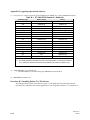
User Manual Change Document This change document revises information contained in the: Synchrony ST-1000/ST-20 Bandwidth Management Installation and Maintenance Manual (MC17233) TM The information in this document supports Release 2.1 of the Synchrony ST-1000/ST-20 Bandwidth Management System. Insert this document directly after the title page of your manual as a record of the change(s). Front Matter (1) The Table of Modules information for SGM Module types should be: Server Modules Module Name SGM-1 SGM-1/19.2K SGM-1/128K (2) Subrate Groomer Module (56Kbps and 64Kbps AD-10 aggregates) Subrate Groomer Module (19.2Kbps and 64Kbps AD-10 aggregates) Subrate Groomer Module (64Kbps and 128Kbps AD-10 aggregates) Under Products Covered by This Manual, the information should read: This manual applies to the Synchrony ST-1000 and ST-20 bandwidth management systems and to the Synchrony AD-3, AD-7, and AD-10 access devices. The ST-1000 accepts both bandwidth management modules and internetworking modules (see the Table of Modules on the following page). Information on ST-1000 operation using the internetworking modules is provided in the ST-1000/ER-5 Internetworking User’s Guide, Volumes 1 and 2, and in the ST-1000/ER-5 Internetworking Installation and Maintenance Manual. • Craft Person Station distribution software, RP66084 • ST-1000 and ST-20 bandwidth management system operational software, RP66080, RP66081, RP66082, RP66083 • AD-10 access device operational software, RP66072 NOTE: For important updated information following the printing of this manual, refer to the accompanying Release Notes. NOTE: Throughout this manual, the term ST node applies to models ST-1000, ST-50, and ST-20. Also, throughout this manual, the term LINK/+ represents the following products: MX17233-1 7/31/97 • LINK/2+ Integrated Connectivity System • LINK/2+ Facilities Management System • miniLINK/2+ Integrated Connectivity System • microLINK/2+ Integrated Connectivity System 1997, 1998 Timeplex, Inc. 1 of 9 • entréeLINK+ System • LINK/100+ Integrated Connectivity System Chapter 2. ST-1000 Installation The following precaution note applies to the bottom of page 2-28: PRECAUTION: If a Revision A RXM Module is being installed in an operational control shelf that previously contained only IRP Modules, the shelf must first be powered down. Otherwise, all of the IRP Modules will be reset when the RXM Module is inserted. The shelf must also be powered down when replacing a Revision A RXM Module. Refer to the “Adding and Replacing ST Units” chapter for information on replacing RXM Modules. Chapter 8. Adding and Replacing ST Units The procedure for replacing LXM and RXM Modules should be as follows: Procedure 8-19. Replacing an LXM or RXM Module This procedure replaces an LXM or RXM module in an ST-1000 node. PRECAUTION: 1. When replacing an LXM or RXM module, all modules and associated interfaces in the same shelf are interrupted, as well as all modules in the shelves beyond the removed LXM or RXM. Therefore, replacement should be scheduled for non-busy times and users should be informed of the interruption. Initiate a loopback on the RXM module in the shelf preceding the shelf that contains the LXM or RXM module that is to be replaced, by entering the command: lp rxm n where: NOTE: 2. n = shelf number All modules on any downstream shelves are disconnected when the RXM module is placed in loopback. For multishelf nodes, logically remove the modules in each shelf, in succession, beyond the powereddown shelf, using the CPS command: rmv shelf n where: 3. 2 of 9 n = shelf number For multishelf nodes, disconnect the front panel upper (A) and lower (B) bus extension cables from the RXM or LXM module to be replaced by loosening the cable connector locking screws and removing the cables. Tag the cables if necessary. MX17233-1 7/31/97 4. Remove the failed LXM or RXM module by loosening the module locking screws, opening the ejector handles, and sliding the module from the module assembly. PRECAUTION: If the replacement module is a Revision A RXM Module and the shelf contains one or more IRP Modules, the shelf must first be powered down. Otherwise, the IRP Modules in the shelf will be reset upon insertion of the RXM Module. 5. If necessary, power down the shelf by setting the circuit breaker(s) on the power entry unit to the OFF position. 6. Slide the replacement LXM or RXM module into the module assembly, close the ejector handles, and tighten the locking screws. 7. Replace the bus extender cables A and B and lock them in place by tightening the locking screws. 8. If the shelf was powered down, apply power to the shelf by setting the circuit breaker(s) on the power entry unit to the ON position. 9. For multishelf nodes, logically insert the modules in each shelf beyond the shelf that was powered up, using the CPS command: ins shelf n where: n = shelf number 10. Clear the RXM loopback in the preceding shelf with the CPS command: clr rxm n where: MX17233-1 7/31/97 n = shelf number 3 of 9 Chapter 9. Modules On page 9-32, the SGM Module Types information should be: The three available SGM Module types are: • SGM-1 (SGM.1) • SGM-1/19.2K (SGM.4) • SGM-1/128K (SGM.3) Chapter 10. Cable Applications On page 10-22, callout 2 under V.24/RS-232/RS-530 Distribution Panels paragraph should read: 2. 100-pin cable connector from P1-4 or P5-8 connector on the SDM-8 V.24 or SDM-8 V.35 module. (See Table 10-8 for pin assignments.) Appendix B The information for the FSM-64 Module in Table B-4 should be: Part Number 65754-3 Module FSM-64 Description 64-Port Frame Server Module The information for the SGM Module in Table B-4 should be: Part Number Module Description 65732-1 SGM-1 Subrate Groomer Module (56/64 Kbps) 65732-3 SGM-1/19.2K Subrate Groomer Module (19.2/64 Kbps) 65732-5 SGM-1/128K Subrate Groomer Module (64/128 Kbps) 4 of 9 MX17233-1 7/31/97 Appendix C. Installing Operational Software All references to software filenames should be 0210 instead of 0201. For example, Table C-1 should be: Table C-1. ST-1000/ST-20 Release 2.1 Software† Software Type NCP-1, NCP-2 NCP-3 map 2map0210.obj 3map0210.obj mib mib0210.obj mib0210.obj ncp ncp0210u.1 ncp0210u.1 ncp ncp0210u.2 ncp0210u.2 ‡ utility unixbncp utility unixcomb ‡ ‡ unixbncp ‡ unixcomb utility dosbncp.bat dosbncp.bat utility doscomb.exe doscomb.exe t1m t1m0210u.obj t1m0210u.obj e1m e1m0210u.obj e1m0210u.obj sdm sdm0210u.obj sdm0210u.obj fsm fsm0210u.obj fsm0210u.obj sgm sgm0210c.obj sgm0210c.obj asm asm0210c.obj asm0210c.obj rtm rtm0210u.obj rtm0210u.obj lgm N/A lgm0210u.obj dsm N/A dsm0211u.obj ‡ = These files are not required when installing software from a PC. † = The filenames listed in this table are those of the initial release. If a maintenance release of 2.1 software is required, the filename will be different (for example, 3map0211.obj). MX17233-1 7/31/97 5 of 9 Appendix D. Upgrading Operational Software (1) All references to software filenames should be 0210 instead of 0201. For example, Table D-1 should be: Table D-1. ST-1000/ST-20 Release 2.1 Software† Software Type NCP-1, NCP-2 NCP-3 map 2map0210.obj 3map0210.obj mib mib0210.obj mib0210.obj ncp ncp0210u.1 ncp0210u.1 ncp ncp0210u.2 ncp0210u.2 ‡ utility unixbncp utility unixcomb ‡ ‡ unixbncp ‡ unixcomb utility dosbncp.bat dosbncp.bat utility doscomb.exe doscomb.exe t1m t1m0210u.obj t1m0210u.obj e1m e1m0210u.obj e1m0210u.obj sdm sdm0210u.obj sdm0210u.obj fsm fsm0210u.obj fsm0210u.obj sgm sgm0210c.obj sgm0210c.obj asm asm0210c.obj asm0210c.obj rtm rtm0210u.obj rtm0210u.obj lgm N/A lgm0210u.obj dsm N/A dsm0210u.obj ‡ = These files are not required when installing software from a PC. † = The filenames listed in this table are those of the initial release. If a maintenance release of 2.1 software is required, the filename will be different (for example, 3map0211.obj). (2) In Procedure D-2, step 3 should read: 3. Insert the Database Conversion Utility tape (RP66086) into the tape drive. (3) Procedure D-3 should read: Procedure D-3. Installing Release 2.1 CPS Software The CPS application software is provided on a single 3.5-inch floppy disk. The following procedure describes how to install the CPS software application on a PC using DOS, Windows 3.1, or Windows 95. 6 of 9 MX17233-1 7/31/97 Installing CPS Software Using DOS To install the CPS software using DOS: 1. Insert the CPS application disk (RP66084) into the floppy disk drive (a: or b:) of the PC that will be used as the craft person station. 2. Start the CPS software installation utility by entering the following command at the DOS prompt: a:\dosinst or b:\dosinst 3. A dialog box appears informing you about the minimum system requirements. To continue with the CPS installation, press the Enter key. NOTE: 4. You may abort the installation program at any time by pressing the Esc key. You are next prompted to enter the destination drive and directory name. You may accept the default drive/directory or choose your own. After selecting the drive and directory, press the Enter key. The CPS application program will now be installed. This takes about one minute. 5. A dialog box will appear signifying that the installation successfully completed. Pressing either the Enter key or Esc key will take you to the CPS directory. Enter the dir command to view the files installed in the CPS directory. One file will be named cps0210.exe, or something similar. This is the executable file that you will use to start the CPS application. NOTE: 6. The filename cps0210.exe only applies to the initial release of CPS software. If a maintenance release is required, the file name will be different. For example, the first maintenance release of CPS software may be named cps0211.exe. Remove the CPS application disk from the drive and store it in a safe place. Installing CPS Software Using Windows 3.1 To install the CPS software using Windows 3.1: 1. Insert the CPS application disk (RP66084) into the floppy disk drive (a: or b:) of the PC that will be used as the craft person station. 2. Start the CPS software installation by choosing File from the Program Manager window and then selecting Run from the menu. Type the following in the Command Line: a:\wininst or b:\wininst Then click on OK. 3. A dialog box appears informing you about the minimum system requirements. To continue with the CPS installation, click on the OK button. NOTE: MX17233-1 7/31/97 You may abort the installation program at any time by clicking on the Cancel button. 7 of 9 4. You are next prompted to enter the Windows Groupname. You may accept the default Groupname or choose your own. After selecting the Groupname, click on the OK button. 5. You are next prompted to enter the destination drive and directory name. You may accept the default drive/directory or choose your own. After selecting the drive and directory, click on the OK button. The CPS application program will now be installed. This takes about one minute. 6. A dialog box will appear signifying that the installation successfully completed. Clicking on the OK button will cause the Timeplex Apps window to appear. You may now start the CPS application by double-clicking on the Craft Person Station icon in the Timeplex Apps window. 7. Remove the CPS application disk from the drive and store it in a safe place. Installing CPS Software Using Windows 95 To install the CPS software using Windows 95: 1. Insert the CPS application disk (RP66084) into the floppy disk drive (a: or b:) of the PC that will be used as the craft person station. 2. Start the CPS software installation by clicking on the Start button and selecting Run from the menu. Then type the following in the Command Line: a:\wininst or b:\wininst 3. A dialog box appears informing you about the minimum system requirements. To continue with the CPS installation, click on the OK button. NOTE: 4. 5. You may abort the installation program at any time by clicking on the Cancel button. You are next prompted to enter the Windows Groupname. You may accept the default Groupname or choose your own. After selecting the Groupname, click on the OK button. You are next prompted to enter the destination drive and directory name. You may accept the default drive/directory or choose your own. After selecting the drive and directory, click on the OK button. The CPS application program will now be installed. This takes about one minute. (4) 6. A dialog box will appear signifying that the installation successfully completed. Clicking on the OK button will cause the Timeplex Apps window to appear. You may now start the CPS application by double-clicking on the Craft Person Station icon in the Timeplex Apps window. 7. Remove the CPS application disk from the drive and store it in a safe place. The Upgrading Operational Software paragraphs should read Upgrading Operational Software to Release 2.1. All instances of upgrading from Release 1.2 to Release 2.0 should read upgrading from Release 2.0 to Release 2.1. 8 of 9 MX17233-1 7/31/97 DISCLAIMER Ascom Timeplex is now Timeplex, Inc. The new company logo is . Please disregard any references to the company’s former name in this manual. Thank you. 1998 Timeplex, Inc. 01/01/98