1
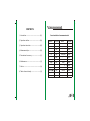
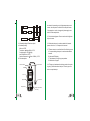
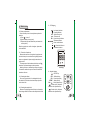
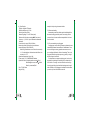
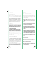
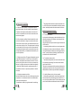
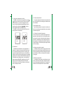
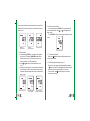
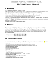
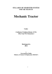
MODEL: GM100
ULTRASONIC THICKNESS GAUGE
INSTRUCTION MANUAL
Ultrasonic thickness gauge
VEL
STORE
CAL
GM100
VERSION GM100-E-0
8. Table of sound velociey
CONTENTS
1
Introduction-------------------------------------(01)
2
Operation codition-----------------------------(04)
Sound velocities of common materials
Material
Aluminum
3
4
5
6
7
Operation instruction--------------------------(05)
Measurement tips------------------------------(09)
Precautions for accurcy-----------------------(11)
Maintenance------------------------------------(13)
Notice --------------------------------------------(14)
Table of sound velocity------------------------(15)
Velocity(m/s)
Material
6320
Acetate resin
Zinc
4170
Phosphor bronze
3530
Silver
3600
Turpentine
4430
2670
Glod
3240
Glass
5440
Tin
3230
Incoloy alloy
5720
Iron/Steel
5900
Magnesium
6310
Brass
4640
Monel alloy
6020
Copper
4700
SUS
5790
Acrylic resin
8
Velocity(m/s)
Nickle
Steel 4330
mild
5630
5850
2730
Steel 330
5660
1480
Titanium
6070
Glycerinl
1920
Zirconium
4650
soluble glass
2350
Nylon
2620
Water
20
-21-
7. Notice
7.1. Warranty and warranty policy
Please fill the warranty card with your cachet/chop after
purchasing this products, the warranty period for repaired is
12 months form the date of original purchase. During warranty period, product must be returned with the invoice(copy)
and warranty card to our customer service department. The
product will not be warranted which without the warranty
card.
Over warranty period, any repairing / maintenance will charge the fee on the buyer in standard rate by local distributor.
The standard rate is not including the accessories which
not packing in standard package(For example, abnormity
transducer, lengthen lead-wire, special software) .
We disclaims any liability due to: transportation damages;
incorrect use or operation; manipulation, alterations or repair attempts; without warranty card, invioce.
7.2. Non-warranty list
LCD, battery, probe, sample block, plastic case,
coupling agent
-20-
1. Introduction
This ultrasonic thickness gauge is an intelligent handhold
product, which adopts ultrasonic measuring principle, and is
controlled by micro processor, provides quick and precise
measurement of thickness for most of industrial material.
This unit is widely used in various precise measurement
for different hardware / parts in industrial realm; one of its
important application is to monitor the level of thickness-decreasing during operation of various and pressure container.
Diffusely applied in manufacture fields, metal processing,
and commercial inspection. The material that conduct and
reflect constant sonic velocity, this product is to be applicable to used.
1.1. Scope of application
This unit is suitable for measuring materials that are good
ultrasonic conductor such as metal, plastic, ceramic, glass
etc., as long as the measured part in two parallel surfaces
for measurement of thickness.
This unit is not suitable for cast iron due to its big crystalloid composition.
1.2. How it work
This unit is comprised of transimtting circuit, receiving
circuit, Hi-frequency oscillator, counter, central unit processor, keypad, and moniter etc., adopting ultrasonic pulse reflect principle. Similar to light-wave measure principal, the
sonic pulse occurs form the unit travels through the material
being measured till reach the interface and reflects back to
determine the thickness of the target material.
See the diagram below:
-01-
Receiving
Feedback wave
P
Counter
Keypad
U
Hi-frequency oscillator
LCD display
C
Display driver
Hardware
Transmitting
1.3. Standard packing & Parts description:
1>. Standard packing:
Main unit-1PCS
Transducer: ( 10mm 5MHz ) 1PCS
Coupling agent: 1PCS 50ml
4mm Sample block: 1PCS
Optional accesseries: ( 10mm 2.5MHz ) 1PCS
2>. Parts description:
Receive socket
Transmit socket
LCD
be cleaned for preventing rust. In higher temperature environment, be sure protect the block form the droplet of water.
If the gauge is not use for a long period, please apply some
antirust on the sample block.
6.5. Avoid shocking/impact. Do not store the unit in high humidity enviroment.
6.6. When the tolerance is over than stated in this manual,
please refer to the 3, 4, 5 chapter, in this manual.
6.7. Please contact us or our distributor if the following occurs:
A. Component being destroyed, no readout and enable to
measure.
B. Abnormal LCD display.
C. The tolerance is too big in proper operation.
D. Malfunction of keypad.
6.8. This gauge is a advanced technology product, the repairing only by technician authorized by us, do not try any alterations or repair attempts.
Case
Keypad
Ultrasonic thickness gauge
Transducer
VEL
STORE
Sample block
-02-
CAL
Battery compartment
(rear case)
-19-
6. Maintenance
6.1. Battery replacement
When low battery icon is showed, please replace the
batteries.
A. Press
to turn off.
B. Open the battery door properly.
C. Replace the low power batteries by new batteries in
correct polarity.
When the gauge is not used for a long time, please take
out the batteries.
6.2. Protection of transducer
Because the wear face of transducer is propylene material which easy to be scratched. During taking measurement on rough material, please using the transducer in
gentle motion.
The temperature of the hardware should not over 60 ,
otherwise it will cause damage on the transducer.
Adhering oil, dust on the wear face will speed up aging
of transducer and lead to rupture. Clean the lead-wire &
transducer after use.
6.3. Cleaning the cabinet
Do not use solvent/alcohol for cleaning which erode
the cabinet & LCD window, brush and sweep only with a
moist cotton cloth.
6.4. Cleaning the sample block
Because of coupling agent should be put on the sample
block during calibration, after use the sample block should
-18-
3>. LCD diagram
-- Low battery indicator
-- Coupling indicator
m/s -- Sound velocity unit
mm - - Thickness unit
VEL -- Sound velocity indicator
-- Thickness indicator
-- Store / recall indicator
--- Stored unit indicator
-- Calibration indicator
LCD display
4>. Keypad diagram
-- ON/OFF key
CAL -- Calibration key
VEL -- Sound velocity key
STORE -- Mode shift key
CAL+
--Back light active key
--Sound velocity, thickness,
thickness unit adjust/recall key
--Sound velocity, thickness,
thickness unit adjust/recall key
VEL
CAL
STORE
KEYPAD
-03-
1.4. Specification
Display: 4-digital LCD display
Minimum display unit: 0.1 mm
Working frequency: 5MHz
Measuring range: 1.2 to 225.0mm (steel)
Minimum limit for tube measuring: 20*3mm (steel)
Accuracy: +/- (1%H+0.1)mm H denotes the measured
thickness.
Sound velocity range: 1000 to 9999 m/s
Measuring sound velocity with a given thickness:
measuring range:1000 to 9999 m/s.
When the given thickness over 20mm, the accuracyis
+/-1%; when the given thickness less than 20mm, the
accuracy is+/-5%.
Operation temperature: 0 to 40
Power supply: 3*1.5V AAA alkaline batteries
Operation current: Normal operation current 50mA
With Backlight turn on current 120mA
Stand-by current: 20uA
Size: 72*146*29mm
Weight: 202g
-04-
sample block by using micrometer/caliber.
5.8. Abnormal reading
A seasoned operator should be capable to distinguish the
abnormal reading, practically result from rusting, erosive
recess surface / incorrect calibrate sample block/ the inner
flaw of material.
5.9. Choose and using coupling agent
Coupling agent serves the high frequency ultrasonic wave
transmitting between the transducer to the hardware. Choose incorrect agent or wrong operation man cause error or
poor coupling which lead to failure of measuring. The coupling agent should be used in proper way, typiccally, a single
droplet of agent is sufficient.
It is important to use proper coupling agent, low viscosity
agent(the provided agent / machining oil) is suitable for smooth surface. For rough / veritcal / aluminum surface, high
viscosity agent like glycerin and lubrication grease is applicable. All kinds of coupling agent is available in local market,
you can buy it form local distributor as well.
-17-
the calibrated value.
5.4. Abrasion fo the transducer
Because the transducer is made of propylene, long period
use will cause the surface of transducer became more rough
which will decline the sensitivity lead to the wrong reading.
Please polish the surface with sand paper or whetstone to
assure the smoothness and parallel. If the reading still unsteady, the transducer should be replaced with new one.
5.5. CAL function
CAL (calibration) is used to calibrate the unit with the stan
dard block on the panel, do press this key for calibration with
other materials or will the wrong measuring will take place.
5.6. Multilayer / composite material
It is impossible to read out the thickness of the uncoupled
multilayer for the ultrasonic wave can not go through the uncoupled space. Further more, the sonic wave cannot travel
in the composite material at an even speed, so ultrasonic
reflect principle cannot be applied for measuring the multilayer/composite material.
5.7. Influence from the oxidized surface
For some metals, such as aluminum a layer of oxide being
generated on their surface. The oxidized layer combined with
the substrate tightly,but the sonic wave travel within 2 different material which will lead to error reading, the more oxidized layer the reading will be more tolerant.
Please calibrated the unit with the sample block that pick up
along the hardware to be measured, and obtain the thick of
-16-
1.5. Features
Auto calibration to assure the accuracy.
Auto linear compensation: this advanced software program enhances the precision by correcting the non-linear
accuracy of transducer.
Use and
keys to make a quick adjustment for the sound velocity /thickness,and a quick recall to the stored
data.
Coupling status indication: Observing the coupling icon to
learn if the coupling is accomplished or not.
10 thickness measurement storage and recall function
available, which facilitates the height work or working in
wild area.
Sound velocity measurement: With a given thickness by
a sample hardware to measure the sound velocity, which
avoid the further conversion or consultation of the table.
12 sound velocity for different material which also adjustable.
Low battery indication
Auto power off mode designed to conserve battery life.
More than 10000 times long lift keys.
The unit has a special memory that retains all of its setting
even when the power is off.
-05-
2. Operation condition
2.1. Operation area condition: For areas that is equal or
bigger than the area, this unit is suitable for measurement.
To measure the slim parts axially that is not vertical to the
surface, the area shall not be too small, otherwise the error
measure may happen.
2.2. Curved surface condition: When the material is curved
surface like boiler wall or tubing, the curvature radius must
be more than or equal to10 mm, and the wall thickness must
be more than or equal to 3 mm. This requirements is referring
to steel material, as for the curve surface of other materials
measuring requirements we still can not provide exact data,
we highly appreciate if you feedback us and share with your
precious experience.
This gauge with the function to measure the sound velocity, so the velocity can be obtained before thickness measurement, and then proceed with measurement of thickness.
5. Precautions for accuracy
5.1. For very thin material
Any ultrasonic thickness gauge, when the thickness of the
material to be measured is less than the minimum limit the
fault reading will occurs.
Using sample block compare method to get a minimum limit
of this material.
In measuring the thin material, an error may happen that
the reading is two times as the actual dimension. Another
error which display the reading much more bigger than the
actual. To prevent the wrong reading by double check out
the minimum limit in the thin material.
2.3. Roughness condition: This gauge wildly applies upon the
rough hardware/material, for most cases, our provided transducer can make exact measurement. However, if the roughness is too big due to the rust etc. the error measure may
happen, in such case, please try to minimize the roughness
or select the 2.5MHz transducer (optional accesseries). If
the transducer is worn out, please re-purchase on the local
distributor.
5.2. For stained, rusting surface
The stained/rusting surface on the contra side will occurs
the ruleless wrong readings. Sometimes a small stained
spot is hard to find out.
Take care for measurement while measuring the known throughsting spot/suspicious area. Or using sound insulation
boardcelotex to locates the spot in different testing angles.
2.4. Working temperature condition
Material thickness and sound velocity will change along with
temperature. In normal measurement, environment temperature impact can beignored.
The transducer is made of propylene material, considering
5.3. Identify different velocity with vary material
A fault reading would obtains, when measuring the hardware with the velocity calibrated by prior material. So a correct velocity should be adopted. The fault reading may also
result form the difference between the actual velocity with
-06-
-15-
please see for calibration operations.
In different material & situation, only one sample block
may not satisfy every calibration. The more similar sample
block, the more exact reading obtained. Ideally, referring
block is a group of different thickness and same material, by
calibrating to the referring block, the effect of variation of
sound velocity will be minimized. To get the most exact measure, a set of referring block is very important.
In most situations, using one referring block will get a satisfying measurement. This referring block must be the same
material with same thickness as the parts to be tested. The
referring block should be read out the thickness by
micrometer.
When measuring thin material which thickness close to
the minimum limit range of this unit, please use a referring
block to define exact limit of this material( 1.2mm for steel
material). Do not measuring the material that the thickness
under the minimum limit.
When material is a complex alloy in a large size. A block
that has a similar thickness with the material should be
selected for calibration.
For most hardware by forging / casting, their have different inner structure, so that the sound velocity slight different.
To reach the exact reading, the referring block has similar
structure as the hardware.
In comment measurement, you check the sound velocity
on the table stated on this manual instead of taking calibration for the referring block. However, this table just for reference, sometimes the sound velocity will be different cause
by different physical / chemical factors. The sound velocity
of mild steel is adopted on the reference table.
-14-
the protection of the transducer and its precision we recommend that the surface temperature of the hardware/
workpiece should not be over 60 , otherwise the transducer can not put into use.
Operation temperature: 0~40
Relative humidity: <90%RH
Hardware/workpiece/material temperature: <60
Do not apply in violent vibration / erosive material.
Avoid impact and humidity.
3. Operation instruction
3.1. Before measurement
1>. Connect the transducer with the main unit, press
to turn on,LCD display full screen for 0.5 second with
back light, then
icon will keep scanning with figure
testing in 2 times. After that, LCD display the last
applied sound velocity with registered memory unit,
indicating the gauge is ready for use.
Full screen
Last applied sound
velocity & registered unit
-07-
2>. Sound velocity adjustment & revision
Press VEL to entre sound velocity adjustment, press
or
to select your desired velocity (There are 12 velocity
stored in this unit). If you need to customize the sound
velocity, during the adjustment press VEL again to enter
velocity revision, while pressing
or
to revise the
velocity, VEL and m/s icon will keep blinking.
Press VEL to confirm and save the revised velocity, the
unit will go back to normal status.
Velocity adjustment
Velocity revision
3.2. Calibration
A calibration should be made for every replacement of
transducer or batteries, this operation is sufficiently important to assure the measuring precision. If necessary, this
step should repeated when the accuracy is critical. Before
calibration, put few provided coupling agent on the standard
sample block to couple the transducer and the sample block.
Press CAL to enter calibration mode, the vertical bar will
keep scanning with CAL, VEL, m/s display, until the LCD
display 4.0mm indicating the calibration is completed.
After calibration, sound velocity will back to your selected
value, and ready to measure.
-08-
4.5. Complex shape material
For complex shape material measurement, please refer to
the 4.4,the smaller of the two reading should then be taken
as the thickness.
4.6. Non-parallel surface
To get a satisfying ultrasonic response, the surface must
have its one measuring side parallel with another, otherwise
will obtain wrong result.
4.7. Influence of the material temperature
The size & sound velocity of material will change with the
temperature, when the precision is critical, please make measurement in 2 samples of the material under the same temperature to determine the proper reading resulting from
the temperature. When taking measurement for steel parts
in high temperature, this method may be adopted to obtain
the correct reading.
4.8. High acoustic reduction material
For materials in fiber, poriferous or big granular, acoustic
dispersion will cause the energy attenuation that may result
in abnormal readings (practically the reading less than the
actual thickness), in this case, the material is not suitable
for the gauge.
4.9. Reference sample block
For calibration for the gauge, a given thickness or sound
velocity of the material is very import. Calibration needs at
lest one referring standard sample block. This gauge is provided with a 4.0mm sample block on the front cabinet,
-13-
4. Measurement Tips
4.1. Cleaning surface
Before measuring, the dust, dirt, rusting and grease etc
that adheres on the hardware/workpiece must be removed
off and cleaned.
4.2. Decreasing the roughness of surface
Too rough surface may result in measure error/ fault reading. Please try to make the surface smooth by milling, polishing, filling or using high viscosity coupling agent.
4.3. Rough machining surface
The regular tiny texture/slots resulting form rough machining process may cause error, and the compensation method is the same as in 4.2,adjusting the angle between the
crosstalk segregating board of the transducer a metal membrane crossing the detector bottom centre and linear texture
/slots (parallel or vertically) may also get a better result.
4.4. Measuring pipe and tubing
When measuring cylindrical parts to determine the thickness of the pipe wall, orientation of the transducers is important. If the diameter of the pipe is large than approximately
4 inches, measurements should be made with the transducer
oriented so that the gap in the wearface is perpendicular (
at right angle) to long axis of the pipe. For smaller pipe diameters, two measurements should be performed, one with
the wearface gap perpendicular, another with the gap parallel to the long axis of the pipe.
The smaller of the two displayed values should then be
taken as the thickness at that point.
-12-
Calibration statu
Calibration accomplished
3.3. Thickness measurement
Put the coupling agent on the area to be measured to couple the transducer with the hardware/workpiece, LCD will
display the thickness reading.
Notes:
icon on the screen indicates a well coupling, if
the icon flashes or not shows that means a poor coupling.
After remove the transducer, the reading will be hold.
In a well coupling
measurement
Measurement
accomplished
3.4. Sound velocity measurement
With a given thickness to read out sound velocity of material: Obtains the thickness of material by using vernier caliper / micrometer, then couple the transducer with that sample material until a reading displays on the LCD, remove
the transducer and press or
to adjust the reading to
-09-
match the thickness by caliper/mirometer, then press VEL to
display the sound velocity and save in current soud velocity
memory unit.
Measuring
the thickness
Adjusting
actual thickness
3.6. Review the saved data
In normal status, press STORE for 2 seconds will enter
into review data mode, press
or
will display saved
data orderly.
Press STORE to exit the review mode and back to normal
status.
Velocity read out
Review saved data
3.5.Data storage
1>. Keep pressing STORE for 2 second to enter the data
store mode ,LCD display THICKNESS, mm, M icon
with first memory unit. If the first memory unit is not
being registered, so LCD will display 0.0.
2>. Press
or
to select your desired memory unit
(1-10).
3>. After picked up the memory unit, the new measurement
will be renew the memory unit, when the measurement
completed the last reading will be stored in the selected
memory unit.
Select memory unit
-10-
Taking measurement
& saving data
3.7. Low battery indication
When icon
flashes, please replace the batteries for
further measurement.
3.8. LCD back light & Automatic power off
Before turn on the gauge, hold pressing CAL, and press
button to turn on, the back light will be activated every
operation will turn on the back light for 7 seconds .
This unit will be turned off automatically in 2 minutes
without any operation.
Measurement &
storage accomplished
-11-