1
© KROHNE 03/2004
7.02267.22.00
GR
Handbook
BM 102
MICROFLEX
T D R Level gauge
2-WIRE
Variable area flowmeters
Vortex flowmeters
Flow controllers
Electromagnetic flowmeters
Ultrasonic flowmeters
Mass flowmeters
Level measuring instruments
Communications technology
Engineering systems & solutions
Switches, counters, displays and recorders
Heat metering
Pressure and temperature
Subject to change without notice.
Table of contents
Device description and range of applications ……………………………………………………….. 4
Principal gauge components ……………………..………………………………………………….…. 4
Items included with supply …………………………………………………..…………………….……. 6
Documentation supplied …………………………………………………..……………………….……. 6
Product liability and warranty ………………………….………………………………………….……. 6
1
1.1
1.2
1.3
1.3.1
1.3.2
1.3.3
1.3.4
1.3.5
Mechanical installation.........................................................................................................7
Handling and storage ..............................................................................................................7
Installation restrictions.............................................................................................................8
Mounting on the tank...............................................................................................................8
Installation instructions: general notes ....................................................................................8
Installation instructions: nozzle................................................................................................9
Installation instructions: Gauge - all applications...................................................................11
Specific installation instructions: gauge - liquid applications .................................................14
Specific installation instructions: gauge - solid applications ..................................................16
2
2.1
2.1.1
2.1.2
2.1.3
2.1.4
2.2
2.2.1
2.2.2
2.3
2.3.1
2.3.2
Electrical connections ........................................................................................................18
Electrical installation instructions...........................................................................................18
Wiring general notes .............................................................................................................18
Wiring connections: DIN connector .......................................................................................18
Wiring connections: M16 terminal box ..................................................................................19
’Ex’ equalizing conductor ......................................................................................................19
Power Supply ........................................................................................................................20
Non-hazardous-duty version .................................................................................................20
Hazardous-duty version ........................................................................................................21
Electrical output.....................................................................................................................22
Network options ....................................................................................................................22
HART® communication protocol ...........................................................................................22
3
3.1
3.2
3.3
3.3.1
3.3.2
3.3.3
3.3.4
3.3.5
3.3.6
3.4
3.4.1
3.4.2
3.4.3
User interface ......................................................................................................................23
Power-on and start-up...........................................................................................................23
Available user interfaces .......................................................................................................23
Operator control ....................................................................................................................23
PCSTAR 2 for Windows : basic installation & operating instructions ....................................23
Summary of User Functions in PCSTAR 2 (F2 – Configuration)...........................................27
Quick Configuration: configuration examples ........................................................................33
HART® Communicator: installation & operating instructions ................................................38
Characters available for alpha-numerical data functions in PC STAR 2 and on the HART®
console..................................................................................................................................46
Local user display (instruments equipped with DIN connectors only) ...................................47
BM 102 MICROFLEX T.D.R. meter characteristics...............................................................48
Gauge operating logic when the reflection is lost ..................................................................49
Gain and voltage amplitude ..................................................................................................50
Level measurement when more than one phase or layer in the tank ....................................56
4
4.1
4.2
Service / Maintenance.........................................................................................................57
Replacement of the signal converter.....................................................................................57
Fault clearing.........................................................................................................................59
2
BM 102
5
5.1
5.1.1
5.1.2
5.2
5.2.1
5.2.2
5.2.3
5.3
Technical data .....................................................................................................................63
Technical data ......................................................................................................................63
Accuracy ...............................................................................................................................65
Start-up characteristics .........................................................................................................66
BM 102 equipment architecture ............................................................................................67
BM 102 mechanical options (by probe type).........................................................................67
Definition of terms .................................................................................................................69
Probe measurement limits ....................................................................................................70
Gauge dimensions ................................................................................................................71
6
Measuring principle ............................................................................................................72
6.1
General principle...................................................................................................................72
6.1.1 Level measurement of one product.......................................................................................73
7
Certificates and Approvals ................................................................................................74
8
8.1
8.2
8.3
8.4
8.4.1
8.4.2
8.4.3
8.4.4
8.4.5
8.4.6
8.4.7
8.5
PCSTAR 2 software user’s guide ......................................................................................75
Software installation..............................................................................................................75
PCSTAR 2 software history ..................................................................................................75
Supported networks ..............................................................................................................75
PCSTAR 2 functions .............................................................................................................75
F1 Help .................................................................................................................................76
F2-Connection: on-line functions ..........................................................................................76
F3 Exit:..................................................................................................................................84
F4 Serial (parameters): .........................................................................................................84
F5 Record (Reading): ...........................................................................................................84
F9 Colors ..............................................................................................................................87
Other important PCSTAR 2 functions ...................................................................................87
Fault Clearing PCSTAR 2 .....................................................................................................88
Appendix A: BM 102 Level Gauge Configuration Record ………………………………………... 89
Appendix B: BM 102 – CE Declaration of Conformity…………………………………………..…. 90
Appendix C: Returning a device for testing or repair to KROHNE …………………………..…. 91
BM 102
3
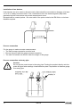
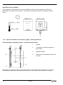
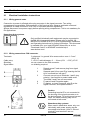
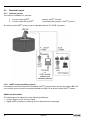
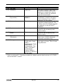
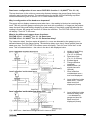
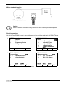
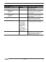
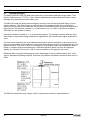
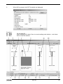
Device description and range of applications
The BM 102 MICROFLEX level gauge uses the Time Domain Reflectometry (TDR) measuring
principle and two-wire technology for level measurement. It is designed solely for measuring the
distance, level, volume and ullage of liquids, pastes, slurries and powder products. It can continue to
measure the level or distance and total volume in applications with two products.
The level measurement data can be displayed and the gauge configured using either a HART
Handheld Communicator console (HHC) or a PC work station equipped with PCSTAR2 software
supplied as standard with the gauge.
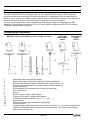
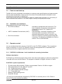
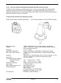
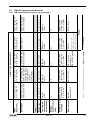
Principal gauge components
BM 102 housing and probes (non-Ex and Ex versions)
1
2
3
4
5
6
7
8
9
10
11
12
13
14
15
4
with hightemperature
option
with inactive
length
option
Nameplate (see next page for details)
Cable entry (output and power supply) to wiring compartment
Equi-potential bonding system connection (Ex – see section 2.1.4)
Flange (process connection onto tank or other suitable mounting)
Single cable probe
Counterweight (with threaded hole in base for anchoring)
Twin cable probe
Spacer
Chuck / ring (for single cable probes)
Turnbuckle (for twin or single cable probes)
Threaded process connection (e.g. 1” G, 1” NPT, …)
Coaxial probe
Extension tube for high temperature applications
Single rod probe
Inactive length: coaxial tube under the process connection (i.e. an inactive length of the
probe) for installations with long nozzles or concrete roofs – for single rod and single
cable probe versions only
BM 102
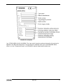
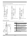
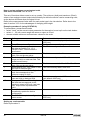
Standard nameplate
*eg. VF030415B0112110110100000. The “type code” gives the options chosen for this unit and is
defined in the BM 102 Data Sheet. This document is available from your local KROHNE Sales
office or on the “Download Centre” on KROHNE’s website http://www.krohne.com/.
BM 102
5
Items included with supply:
The scope of supply encompasses:
• Signal converter with probe in the version ordered. The version is stated on the nameplate.
• PCSTAR 2 computer software for data display and gauge configuration.
Documentation supplied:
Installation & Operating instructions:
Installation, connection, start-up and safety advice in condensed form, but sufficient for most
applications. This is supplied as a printed document with the device delivered.
Handbook (this manual):
Detailed user manual and reference book, including how to configure meter parameters available in
the user menu and how to perform basic maintenance. This is not shipped with the level meter
ordered.
Supplementary Installation and Operating Instructions BM 102 KEMA 00 ATEX 1101X:
Supplementary instructions covering devices to be installed and used in hazardous areas. This
document is only supplied with specially approved instruments. This document is available from
your local KROHNE Sales office or on the “Download Centre” on KROHNE’s website
http://www.krohne.com/.
Product liability and warranty:
The BM 102 TDR level gauge is designed for measuring the distance, level, and volume of liquids,
pastes, slurries and powders. It may equally measure level, distance, total volume and ullage in
applications where two or more products are present.
Special codes and regulations apply to its use in hazardous areas. Please refer to the BM 102
MICROFLEX KEMA 00 ATEX 1101X Supplementary Installation and Operating Instructions for
further information. This document is available from your local KROHNE Sales office or on the
“Download Centre” on KROHNE’s website http://www.krohne.com/.
Responsibility as to suitability and intended use of these level gauges rests solely with the user.
Improper installation and operation of our level gauges may lead to loss of warranty.
In addition, the "General conditions of sale", forming the basis of the purchasing contract, are applicable.
If you need to return measuring instruments to KROHNE, please note the information given in
Appendix C. KROHNE regrets that they cannot repair or check your device unless it is
accompanied by the completed form.
The level gauge does not form part of an overfill protection system (as defined for example in
WHG: German water resources act) nor is it concerned by the Pressure Equipment Directive (PED)
97/23/EC.
6
BM 102
1
Mechanical installation
1.1
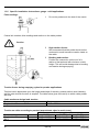
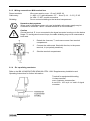
Handling and storage
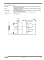
To carry: the device will weigh between 3 kg or 7 lb and 12 kg or 25 lb. Carry using
both hands to lift the device carefully by the converter housing. If necessary, use
lifting gear.
No attempt should be made to lift the instrument by its probe.
Caution:
The probe is a critical gauge component.
Do not damage– Handle with care!!!
Avoiding blows
When handling the BM 102, avoid hard blows, jolts, impacts, etc.
Caution:
Fragile electronics
Avoid bending (single rod and coaxial probes)
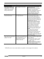
Support the probe to avoid bending.
Support probe here
BM 102
7
Avoid cable kinks and fraying
Do not coil the cable less than 400 mm or 16 “ in diameter. Cable kinks or fraying will cause
measurement errors.
Storage temperature
Store within the given storage temperature limits.
1.2
Installation restrictions
Hazardous-duty systems (Ex, FM,…)
• Refer to the BM 102 MICROFLEX KEMA 00 ATEX 1101X Supplementary Installation and
Operating Instructions for further information on installing gauges approved for use in
hazardous locations. This document is available from your local KROHNE Sales office or on the
“Download Centre” on KROHNE’s website http://www.krohne.com/.
• Check that the flange, gasket and probe materials are compatible with the product. Read the
information given on the converter nameplate, the flange markings and specifications in the
approval certificates.
1.3
Mounting on the tank
1.3.1 Installation instructions: general notes
The fitter should give some thought to tank fittings and tank shape.
• Nozzle position in relation to the tank walls and other objects inside the tanks
(Warning : this free area will depend on the probe type selected: refer to later on in this section)
• Type of tank roof, i.e. floating, concrete, integral, etc; and base, i.e. conical, etc.
Whenever working on an installation, remember to:
• Disconnect the power supply before starting work.
However,
• The gauge may be installed when the tank contains product.
8
BM 102
1.3.2 Installation instructions: nozzle
Threaded process connections
Nozzle height
Recommendation
Do not fit a nozzle longer than its
diameter , especially for single
probes and powder applications
The simplest and most economic way is to
mount the BM 102 directly on the tank with a
GAS or NPT threaded connection.
h ≤ Ød
, where h = nozzle height and
d = nozzle diameter
Contact KROHNE if this relationship cannot be
respected.
Nozzles extending into tank
Caution:
Do not use nozzles that extend into the tank. This will disturb the electromagnetic
emitted pulse and the measurement.
BM 102
9
Installation of two devices
If two devices are to be used on the same tank, these should be mounted at a distance of at least
2 m or 6 ¾ ft away from each other. If not, interferences from the electromagnetic (EM) fields
generated by both instruments may cause measurement errors.
Not applicable to coaxial probes - the outer shell of the probe contains the EM field: no minimum
distance required.
Process connection
For the gauge to make accurate measurements:
• The tank process connection must be level.
• Ensure a good fit with the gauge process connection
• The tank roof should not deform under the weight of the gauge
Process connection and entry pipe
Caution:
Do not put the nozzle close to the entry pipe. Pouring the product directly onto the
probe will give false readings. Install deflector plate if impossible to distance gauge
from entry pipe.
10
BM 102
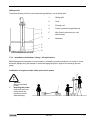
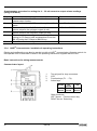
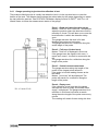
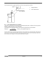
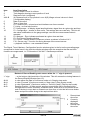
Stilling wells
Tanks with floating roofs for petro-chemical applications: use a stilling well.
1
Stilling well
2
Tank
3
Floating roof
4
Product (petroleum applications)
5
Well fixed to tank base (no roof
deformation)
6
Sediment
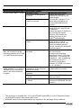
1.3.3 Installation instructions: Gauge - all applications
BM102 gauges are designed to be mounted on a suitable process connection on a tank or sump.
Install the gauge using two people to avoid damaging the probe. Support the housing and the
probe.
Installation of single and twin cable probe level meters
1
2
Caution :
Do not over-bend
probe!
Inserting the probe:
hold more than one
metre above the
opening to avoid
cable bending.
BM 102
11
Probes: entanglement, straightness and tank bottom clearance
Rigid section length of single
and twin cable probes
Cable diameter
Rigid section length
Single cable
Ø4mm or 0.15”
40mm or 1½”
Ø8mm or 0.15”
200mm or 8”
Twin cable
Ø4mm or 0.15”
40mm or 1½”
•
•
Cable probes must be straight once inserted into the tank. They must also be far from other
objects (e.g. mixers) to avoid entanglement.
In order to maintain the gauge’s operating characteristics, it is recommended to avoid touching
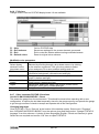
the tank bottom with the counterweights (for cable probes) or probe end (other types).
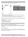
Objects (discontinuities) inside the tank that influence the probe’s EM (electromagnetic) field
Install the gauge far from protruding objects such as:
• Heating tubes,
• Sudden changes in tank cross-section,
• Tank wall reinforcements and beams,
• Weld lines and dip-stick pipes, etc...
TDR gauges generate electromagnetic (EM) fields when a measurement pulse is emitted. This field
is affected by any nearby discontinuities and these will weaken and potentially block the emitted
pulse. A minimum distance is recommended depending on the probe type to be installed. See the
table on the next page for recommended free space dimensions.
Alternatively, the fitter may use a reference chamber or stilling well. However, the chamber walls
must be smooth (i.e. no visible weld lines), straight and vertical to maintain the pulse strength and
gauge accuracy.
For clean applications only :
Coaxial (type 3) probes may be used close to or touching objects or walls as the EM field generated
by the probe is contained within the probe’s outer sheath (refer also to the EM field sizes/free area
given in the figures on the next page).
12
BM 102
1
Agitator
2
Support beam perpendicular to the
pulse direction
3
Abrupt changes in tank cross section
4
Heating tubes
5
Alternative solution: reference chamber
-electromagnetic field is contained
within chamber
6
Gauge electromagnetic field:
Any intruding metallic object will be
detected in this zone if perpendicular to
the emitted pulse direction.
= Do not fit the gauge near to these objects.
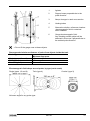
Recommended minimum distance of probe from objects inside the tank
Probe Type
Minimum free space
Single (types 1,2 and 6)
300 mm or 12”
Twin (type 4)
100 mm or 4”
Coaxial (type 3)
0 mm or 0”
Electromagnetic field shape around probe, by type (not to scale)
Single (types 1,2 and 6)
Twin (type 4)
Coaxial (type 3)
No beam angle for any probe type.
BM 102
13
Avoid direct solar radiation
Fit a sunshade on the gauge for open-air installations: this is either supplied on demand by
KROHNE or provided by the customer. The ambient temperature limits of the gauge are given
below.
1.3.4 Specific installation instructions: gauge - liquid applications
Probe bending in agitated products: recommended solutions
1
Agitator
2
Turnbuckle for anchoring probe to
tank bottom
3
Bypass chamber
4
Probe and counterweight (centred on
request)
Mounting on a reference vessel or still well is ideal. To ensure that the probe does not come into
contact with the tank wall, the probe should be fixed to the bottom of the chamber or centred.
14
BM 102
Fastening the probe to the tank bottom
Flexible probes can be fastened with a chuck (ring), turnbuckle or similar fastening device to the
tank bottom:
Chuck (ring)
Turnbuckle for Ø8 mm cable
probes
Turnbuckle for Ø4 mm cable
probes
Shortening cable probes
If required, the cable probe can be shortened, but this applies only when used in liquids.
Procedure
Step
Action
1
Detach socket set screw M6x10 (ISO
4026) with a 3mm Allen (hexagon) key
(ISO 2936).
2
Pull cable (2) out of counterweight (3)
and shorten to required length using
cable cutters to prevent the cable wires
and strands from splaying out.
3
Insert cable back into counterweight and
tighten down screws
4
Change configuration parameters to new
probe length; the reference point is the
top edge of the weight (user menu
function 1.1.6)
Dimensions in mm (inches).
BM 102
15
1.3.5 Specific installation instructions: gauge - solid applications
False readings:
1
Do not let probe touch the side of the nozzle
Conical silo nozzles, false readings and traction on the cable probes
Caution
2
High traction forces :
We recommend that the probe should not be
anchored to avoid excessive traction loads on
the cable.
3
Bending and traction:
Position the connection on the roof at ½
radius of the tank and with minimum nozzle
height. This will avoid damage due to bending
and traction during emptying.
Traction forces during emptying cycles for powder applications
Traction load is dependent upon the height and shape of the tank, product particle size & density,
and the rate at which the tank is emptied. The table below gives the load up to which cable probes
will hold.
Cable maximum design load, traction
Probe
Single cable Ø8 mm or Ø0.3”
Maximum Load
3.5 T or 7700 lb
Traction on cable according to product (approximate value in metric tons)
Probe Length / m (ft)
Probe used
Material
10 (33)
20 (65.5)
24 (79)
Single cable Ø8mm or
Cement
1.0 T or 2200 lb
2.0 T or 4410 lb
2.4 T or 5290 lb
Ø0.3”
Flyash
0.5 T or 1100 lb
1.0 T or 2200 lb
1.2 T or 2650 lb
16
BM 102
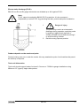
Electro static discharge (E.S.D.)
BM 102 non-Ex and Ex gauge electronics are shielded up to 4kV against E.S.D..
Note:
E.S.D. cannot be solved by BM102 E.S.D. protection. It is the customer’s
responsibility to avoid E.S.D. by grounding the tank, product and probe installation.
1
Danger of injury
2
The probe may receive an electrostatic
discharge during operation; earth the probe
by pushing it against tank wall with a
suitably isolated tool just before touching it
to avoid receiving a shock.
Earth the entry pipe and product.
Product deposits on the nozzle and probe
Product build-up can occur under the nozzle: this may weaken the pulse. Avoid cavities that permit
the build-up of deposits.
Tank roof deformation
Tank roofs should support loads of at least 3.5 tonnes or 7700lb for gauge installations using
Ø8mm or 0.3” (type 6) single cable probes.
BM 102
17
2
Electrical connections
2.1
Electrical installation instructions
2.1.1 Wiring general notes
Connection to power is effected at the plug connector in the signal converter. Two wiring
compartments are available: DIN connector or M16 terminal box. Observe applicable rules and
regulations for cable connection: VDE 165 or equivalent national regulations.
Always disconnect from power supply before opening wiring compartment. This is not mandatory for
Exi applications.
Hazardous-duty systems
Only certified intrinsically safe equipment may be connected to
the BM 102 in hazardous areas. Please refer to the BM 102
MICROFLEX KEMA 00 ATEX 1101X Supplementary Installation
and Operating Instructions for further information. This document
is available from your local KROHNE Sales office or on the
“Download Centre” on KROHNE’s website http://
www.krohne.com/.
2.1.2 Wiring connections: DIN connector
Terminals:
Cable entry:
Shielding:
Signal cable:
3 poles and 1 x ground. Wire cross-section: max. 1.5 mm²
(AWG 16)
1 x PG11, cable diameter: 8 … 10 mm (0.31 … 0.39”), IP 65
do not connect to the DIN connector.
no shielding required
1
2
3
4
5
Detach screw P and remove plug from signal
converter.
Separate part N from part R by inserting the flat
tip of a screwdriver into gap F.
Connect current loop to terminals 1 and 2 (any
polarity). Use ferrules to protect cable ends.
Terminals 3 and E are not connected.
Fit parts N and R together again.
Fit gasket, re-insert connector plug R on the
signal converter, and replace screw P.
Caution
Grounding terminal E is not connected to
the housing of the signal converter or to
the device flange. To avoid ground current
loops, the cable shielding may not be
connected at both ends.
Hazardous-duty systems
When used in hazardous areas, only one
intrinsically safe power supply may be
connected to terminals 1 and 2. Ground
terminal E and terminal 3 are not
connected.
18
BM 102
2.1.3 Wiring connections: M16 terminal box
Power terminals:
Cable entry:
Shielding:
Wire cross-section: max. 1.5 mm² (AWG 16)
1 x M16 x 1.5, cable diameter: 3.5 … 8 mm (0.14 … 0.31”), IP 65
for USA: ½” NPT conduit connection
Do not connect shielding to the terminal compartment.
Hazardous-duty systems
When used in hazardous areas, only one intrinsically safe power supply may be
connected to terminals 1 and 2. Ground terminal E is not connected.
Caution
Ground terminal, E, is not connected to the signal converter housing or to the device
flange. To avoid ground current loops, the cable shielding may not be connected at
both ends.
1
Detach the 4 screws, T, and remove cover from terminal
compartment.
2
Connect the cable ends, fitted with ferrules, to the power
terminal, U (not polarity sensitive).
3
Shut the terminal compartment.
2.1.4 ’Ex’ equalizing conductor
Refer to the BM 102 MICROFLEX KEMA 00 ATEX 1101X Supplementary Installation and
Operating Instructions for further information.
Terminal for equipotential bonding
U-clamp terminal,
max. conductor cross-section:
4 mm²/6.2 • 10-3 sq.in. on ’neck’ of signal
converter
BM 102
19
2.2
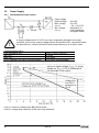
Power Supply
2.2.1 Non-hazardous-duty version
Power supply
Rated voltage
Max. voltage
(Uinput):
Min. voltage
(Uinput):
24 V DC
35 V DC
’Ex’ = 28 V DC
dependent on
load impedance,
see graph below
A supply voltage above 35 V DC can cause irreparable damage to the signal
converter. Also, power supply voltages above the specified max. values and below
the specified min. values can lead to faulty measurements or to a device reset.
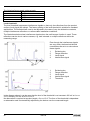
Load impedance Rloop
Loop resistance, Rloop
Min. Rloop
Max. Rloop
RHART resistance for HART® communication
RHART + Rcable + Rammeter
0 ohms
750 ohms
250 ohms (recommended)
Line A = minimum voltage at the BM 102 terminals
Line B = voltage drop caused by a 250 ohm loop resistance
20
BM 102
Example for calculating the power supply:
The voltage drop is tested at 22 mA.
U power min. 22 = 22 mA x load impedance + Uinput min. 22
U power min. 22 = 22 mA x 250 ohms + 10 V = 5.5 V + 10 V = 15.5 V
In order to cover the whole current range, the voltage drop must also be tested at 4 mA.
By analogy, the following applies:
U power min. 4 = 4 mA x load impedance + Uinput min. 4
U power min. 4 = 4 mA x 250 ohms + 18 V = 1 V + 18 V = 19 V
At a load impedance of 250 ohms, a power supply voltage of 19 V is sufficient to energize the
current device range of 4 to 20 mA.
2.2.2 Hazardous-duty version
The certified device may only be used with other ’Ex’ certified equipment. The minimum electrical
safety data indicated on the nameplate must be observed. To ensure proper operation, the
minimum parameters specified above in section 2.2.1 for the power supply must be observed to
ensure that a given 4 to 20 mA converter is adequate for use with the BM 102. Refer to the BM
102 MICROFLEX KEMA 00 ATEX 1101X Supplementary Installation and Operating Instructions
for further information. This document is available from the “Download Centre” on KROHNE’s
website http:// www.krohne.com/.
In addition, the connected
®
equipment must be HART compatible so that it can be
operated with the
communication software or
the HART® communicator.
An ’Ex’ repeater power
supply unit must be used.
For calculation of the supply
voltage the same applies as
for the non-’Ex’ version.
BM 102
21
2.3
Electrical output
2.3.1 Network options
The output is available in 2 versions:
1.
2.
Current output HART®,
Current output Ex-ia HART®
passive, HART® protocol
intrinsically safe; passive, HART® protocol
All versions with HART® protocol can be operated with the PC-STAR 2 program.
®
2.3.2 HART communication protocol
In accordance with the Rosemount Standard, HART® communication can be used with a BM 102.
It is used as a point-to-point connection between the BM 102 as slave and the HART® master.
Additional information
The following can be called up via the following interfaces:
• Current output: 22 mA for error signal.
®
• Digital HART interfaces: scanning of error flags and error messages.
22
BM 102
3
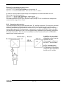
User interface
3.1
Power-on and start-up
The BM 102 is pre-configured in accordance to customer order specifications and measurements
can be made immediately. A start-up time of less than 23 seconds should be allowed for once
connected and the power is switched on.
If the probe length has been shortened since delivery, please refer to section 3.3.1: Summary of
User Functions, user function 1.1.6: Probe length to modify configured probe length.
3.2
Available user interfaces
Measurements may be taken using either:
• PC STAR 2 software
•
HART® Handheld Communicator (HHC)
•
DA 06 local indicator
3.3
Included as standard with the instrument. The
basic installation & operating instructions are
presented in section 3.3.1 (requires PC
workstation).
Sold separately. Automatic recognition of the
instrument when connected. A list of HHCaccessible parameters is given in section 3.3.4.
Sold as an option for devices equipped with DIN
connectors. For displaying readings only. Refer to
section 3.3.6 for technical data.
Operator control
You can configure the device by way of the HHC or the PC-STAR 2 software. This is explained
further in sections 3.3.1 and 3.3.2. Operator control via the separate HHC is described in the
operating instructions supplied with the communicator.
3.3.1 PCSTAR 2 for Windows : basic installation & operating instructions
Software description
PC STAR 2 is a Windows program that permits clear and concise display of data and configuration
of the BM 102 from a remote location. The program is available in English, German or French.
PC-STAR 2 system requirements
•
•
•
•
•
•
•
PC with at least 486 processor 75 MHz, recommended: Pentium 120 MHz or higher
Microsoft Windows 9x, Me, 2000, NT and XP*
min. 16 MB main memory (RAM)
min. 3 MB available hard disk storage
3 ½ “ Floppy disk drive
Mouse or other pointing device
Serial RS 232 port
* XP may not be automatically recognized by PCSTAR 2 in versions prior to V2.01. Refer to
Section 8.5 for the corrective procedure.
BM 102
23
Installing and connecting PCSTAR 2 to the gauge
1.
Connect the HART® adapter (not included in supply) through a load impedance of 350 ohms
maximum (for hazardous-duty purposes, fix to the non-intrinsically safe side of the repeater
power supply unit) and plug it into a serial interface on your PC. The repeater power supply
unit must have HART® capability.
2.
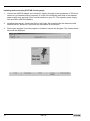
Installing the program: Access the files on the floppy disk supplied with the instrument and
execute the file "setup.exe" and follow the instructions on the screen.
3.
Running the program: once the program is installed, execute the program. The screen shown
below will be displayed.
24
BM 102
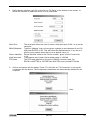
4.
Define device interface: type F4 or left-click on “F4-Serial” at the bottom of the screen - to
define the interface to which the device is to be connected.
Serial Port
BM102 Address
Device Identifier
Initial baud rate
RTS state
5.
The serial port allows the user to select a free serial port (COM 1 to 4) on the
computer.
Type the “Address” that you have given a gauge (a value between 0 and 15)
and press ENTER or OK. This will select the required device. If you are in a
point to point network leave the box at its default value (-1).
Device Identifier refers to the “Device number” given in User Function No.
1.4.4.
Transmission rate of data. Has a default value of 1200 bd.
The RTS state depends on the type of RS232 converter used. For
RS232<>HARTTM(i.e. VIATOR from MACTEK) use inversed RTS state.
On-line connection with the gauge: Press F2 or left-click on “F2-Connection” to set up the
connection with the device - the configuration parameters are automatically loaded into the
computer.
then …
BM 102
25
6.
•
•
•
•
•
•
•
After the connection has been established, the following screen is shown. This will show the
current status of the tank. No further configuration should be necessary. The following functions
are available on the screen and will be discussed further in section 8.4:
F2 – Device configuration: a summary of the parameters are given on the next page,
F7 – Oscilloscope function: have all reflections occurring at the probe displayed,
F11 – Dynamic/on-line device configuration,
F4 – View and record all information during operation,
F6 – Trend: observe the level trend since start of the program,
F8 – Marker: read the status of the device
and F10 – make printouts (screen shots).
26
BM 102
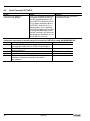
3.3.2 Summary of User Functions in PCSTAR 2 (F2 – Configuration)
The table below provides an overview of all parameters that can be set in the configuration menu
using F2 in PCSTAR2. Reset default values are in bold type in the “Input Range” column.
Function
1.0.0 Operation
1.1.0 Basic parameters
1.1.1 Tank height
Input Range
Description
Enter 0 … 60 m or
0 … 197 ft.
As per order
1.1.2 Dead zone
Enter a value
Fct.1.5.1(Detection
delay) … probe
length.
• Twin probe with
probe length<1m
or 3.3 ft
0.2 m or 8 in
• Single probe or
twin probe with
probe
length >1m
or 3.3 ft
0.4 m or 16 in
• Coaxial probe
0 m or 0 in
1 … 100 seconds
5 seconds
The tank height forms the basis for
calculating level measurements and
for the relevant current output. It is
defined as the distance between the
lower flange surface and the
reference point at the bottom of the
tank.
The output unit is determined via Fct.
1.2.4.: Length Unit
The set tank height is the upper limit
for Fct. 1.3.4: Scale I1 max (if Fct.
1.3.1 is set to “Level” or “Distance”).
Note: the device will not measure
beyond the programmed probe length
if the current output is configured to
measure distance or level .
The dead zone is the minimum
measuring distance from the process
connection (reference point) to the
surface of the product. So as not to
impair measurement accuracy, the
minimum values given in Section
5.2.3 should be adhered to.
The BM 102 will ignore signals in the
dead zone and display the last
reading taken.
The output unit is set via Fct. 1.2.4:
Length Unit
Warning : Critical Parameter
1.1.3 Time constant
BM 102
This function filters possible signal
fluctuations when the liquid is
turbulent.
27
Function
1.1.6 Probe length
28
Input Range
Enter 0.1 m or 3.9” …
probe length (max.:
24000 mm or 78¾ ft.)
As per order
BM 102
Description
This value must be equal to the exact
length of the probe. This value should
be modified when the probe has been
replaced or shortened (cable probes).
The output unit is set via Fct. 1.2.4
Length Unit.
An automatic search for the probe tip
can be carried out when the tank is
empty to update the parameter using
the function F11 in the “Dynamic
Configuration” menu.
Probe length may be set greater than
tank height but less than 24 m or
78¾ ft. for special installations.
Function
1.2.0 Display
Input Range
1.2.4 Length unit
Select m, cm, mm,
inch, ft or optional
unit*
mm
1.2.5 Volume unit
Select m³, l, US Gal,
ft³, bbl, m³/h, ft³/h, kg,
metric tonnes or tons
US
m³
1.2.6 New unit (length)
1.2.6.1 Unit name
1.2.6.2 Unit fact.
4 ASCII characters
Unit
Min.: > 0.0
Max.: 100 000
1.0
Description
To display readings in the form
and units required
Unit for display of level and distance.
*When “optional unit” selected, you
get to the menu item Fct. 1.2.6: New
unit and can there define userdefined units.
The unit selected here is used in the
following functions:,
Fct. 1.1.1 Tank height,
Fct. 1.1.2 Dead zone,
Fct. 1.1.6 Probe length,
Fct. 1.5.1 Detection delay and
Fct. 1.7.2 Input table*.
If “Level” or “Distance” is selected in
fct. 1.3.1, then the units selected will
also be used in these functions:
Fct. 1.3.3 Scale I1 min. and
Fct. 1.3.4 Scale I1max..
In addition the displayed value will
use the selected unit.
Unit of displayed volume / conversion
value.
Conversion means converting a level
value into a “conversion value”
(usually volume) in order e.g. to
realize a non-linear function as a
factor of the level.
The unit selected here is also valid for
the following function:
Fct. 1.7.2 Input table.
If “Volume” or “Ullage volume” is
selected in fct. 1.3.1, then the units
selected will also be used in these
functions:
Fct. 1.3.3 Scale I1 min.
Fct. 1.3.4 Scale I1 max.
Appears only when “Optional unit” is
selected in Fct. 1.2.4: Length unit.
Name of the new unit (max. 4
characters)
Reference for the conversion factor is
the millimetre.
At a conversion factor of 10, the new
unit is equivalent to 10 mm.
At a conversion factor of 0.1, the new
unit is equivalent to 0.1 mm.
* This list is not exhaustive and also includes the Dynamic configuration menu functions in
PCSTAR 2.
BM 102
29
Function
1.3.0 Current output I
Input Range
1.3.1 Current 1 item
Select Off, Level,
Distance, Volume* or
Ullage volume*
Level
Select 4-20mA or 420mA + 22 mA on
error.
4-20mA
1.3.2 Current 1 range
1.3.3 Scale I1 min.
1.3.4 Scale I1 max.
1.3.5 Error delay
Enter a value from 0
mm** to a value lower
than that entered for
Fct. 1.3.4 Scale I
max.
As per order
Enter value higher
than the value
selected under Fct.
1.3.3. “Scale I min.”
up to tank height or
the maximum volume
table value***
As per order
Select No delay, 10
sec., 20 sec., 30 sec.,
1 min., 2 min., 5 min.
or 15 min.
No delay
Description
This configures the current output.
These functions are independent
from what is displayed.
Selection of the required function for
the current output.
This parameter defines the status
which the current output assumes in
the event of a fault:
4-20 mA (last measured value held in
the event of a fault)
4-20 mA / E = 22 mA (is set to 22 mA
in the event of a fault).
This function defines the lower limit
of the analog measuring range.
It is 4 mA.
The value of this parameter always
has to be lower than the value
selected for Fct. 1.3.4: Scale I1 max.
This function defines the upper limit
of the analog measuring range. It is
20 mA.
The value of this parameter must
always be:
- lower than or equal to the value
selected under Fct. 1.1.1: Tank height
or the maximum volume table value,
- higher than the value selected under
Fct. 1.3.3: Scale I1 min., otherwise an
error message will appear during
parameter check.
This menu is only available when
(4-20 mA / E = 22 mA) has been
selected under Fct. 1.3.2: Current 1
range. With this parameter, a time
delay can be defined for transition of
the current output to 22 mA after an
error has been noted. During the
delay, measurement and the analog
output are held. When the error
disappears, the delay also serves to
return to the measuring mode.
* complete fct. 1.7.2 “Input table” before selecting “volume “ or “ullage volume”.
** or other unit selected in fct. 1.2.4 Length Unit, 1.2.5 Volume Unit depending on the item
selected in fct. 1.3.1 Current 1 Item.
*** depends on the value selected in fct. 1.3.1 Current 1 Item.
30
BM 102
Function
1.4.0 User data
1.4.3 Checksum
Input Range
Description
Read only
1.4.4 Device number**
(Tag number)
00000 01
1.4.5 Serial number
Read only
1.4.6 French command number
Read only
1.4.7 German command
number
Read only
This value is used for identification of
the device software version. The
checksum is tested when starting.
This helps to detect any problems
with the microcontroller.
This parameter assigns an
identification number to the device.
A text consisting of max. 8 ASCII
characters can be entered.
This parameter serves to identify the
respective measuring device. This
number cannot be changed and sets
the address for use with HART®
interfaces.
Factory-programmed number, to be
quoted in case of warranty and
service claims.
Factory-programmed number, to be
quoted in case of warranty and
service claims.
This function can be used for entering
text of max. 15 ASCII characters
(customer information only)
Information on probe type supplied
with signal converter. This is a readonly parameter.
1.4.8
Option**
(Descriptor)
1.4.9 Probe type
Single rod, Twin rod,
Single cable, Single
cable +
counterweight, Single
cable without
counterweight, Twin
cable, Twin cable +
counterweight,
Coaxial, Special 1,
Special 2 or Special 3
As per order
** Refer to section 3.3.5: Characters available for alpha-numerical data functions in PC STAR 2
and on the HART® console.
BM 102
31
Function
1.5.0 Application
1.5.1 Detection delay
Input Range
Enter a value 0 mm /
0 in. to Fct. 1.1.2
Dead zone
As per order
1.6.0 Serial I/O
(serial input/output)
1.6.2 Address
1.7.0
Volume table
1.7.2. Input table
32
Addresses from
0 to 15
0
Select point 01 to 20,
enter level and then
volume values
respectively.
0
(conversion table
not created, volume
measurement not
possible)
BM 102
Description
For difficult applications
This function can be used to define
an area directly below the flange in
which interference reflections (e.g.
from the tank nozzle) are masked.
This value has to be smaller than or
equal to the dead zone (Fct. 1.1.2.).
For integrating into a signal
network. Standard hardware
®
platform for HART is the current
loop with superposed FSK signals.
For a multidrop application the
current output is set to “OFF” and
consequently to a constant 4 mA.
With a multidrop bus, up to 15
®
HART devices can be operated.
With this function, every device
connected to a bus is assigned an
address between 0 and 15 (HART®
protocol). If several devices are
connected to a digital bus, each
device must be assigned a unique
address under which it can then be
identified in the bus.
0
= Analogue output active
1 - 15 = Multi-drop mode active,
analogue output inactive
For calibrating the gauge for
volume measurement.
This function is used for setting up
the strapping table (level/volume). Up
to 20 points can be assigned. Every
new point must be larger than the
preceding one. The units of length
and volume can be changed later
without affecting the settings in the
table.
The units selected for length and
volume in fct.s 1.2.4 and 1.2.5 will be
used here.
3.3.3 Quick Configuration: configuration examples
The minimum functions (fct.) to be configured for a simple measurement are listed below:
Functions
PCSTAR 2
1.1.1
1.1.2
1.3.1 … 4
1.7.0
®
HART
2.1.1.1
2.1.1.4
2.1.3.1 … 4
2.1.7.0
Definition
Tank Height
Dead zone
Current Output
Volume table*
*For volume measurements
Example procedures for each set of functions are given on the following pages. Each procedure is
given in a series of steps in table form and is according to the PCSTAR 2 F2-Configuration
parameter list. Please refer to section 3.3.4 for the equivalent parameters available on the HART®
Communicator.
Definitions for quick configuration
* where PCSTAR 2 Fct. 1.3.1 (HART® Fct. 2.1.3.1) Current I1 Item is configured to “Level”
Typical gauge used for quick configuration examples:
Probe type:
Product measured:
Tank height:
(PCSTAR 2: Fct. 1.1.1,
HART®: Fct. 2.1.1.1)
Dead zone:
(PCSTAR 2: Fct. 1.1.2,
HART®: Fct. 2.1.1.4)
Probe length, L1:
(PCSTAR 2: Fct. 1.1.6
HART®: Fct. 2.1.1.2)
twin Ø4 mm or 0.15 ” cable probe (type 4)
Water (dielectric constant, εr = 80)
10000.00 mm or 33 ft.
0.15 m or ½ ft. (see “probe measurement limits” in section 5.2.3
for the Ø4 mm or 0.15” twin cable probe, type 4)
9.00 m or 29.5 ft. (do not modify unless advised to)
BM 102
33
®
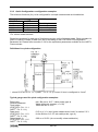
Tank height: configuration of user menu PCSTAR 2 function 1.1.1 (HART Fct. 2.1.1.1)
This function is usually either defined as true tank height or as factory configured probe length, L1
(see diagram on preceding page) if the former is not supplied by the customer in the order.
Why change the tank height?
•
•
®
setting the distance in PCSTAR 2 Fct 1.1.1 (HART Fct. 2.1.1.1) to L1 avoids having a nonmeasurable zone underneath the probe where the measurement on the display freezes.
when setting up a measurement scale as explained on the following pages, this means that
the level at the end of the probe will be taken as zero instead of the tank bottom.
How tank height affects measurement when either Level or Distance is measured
1 Tank height
2 Measurable height
(factory configured
probe length, L1)
3 Non-measurable
zone
4 With true tank
height (1) set in
Function 1.1.1 of
the User’s menu.
5 With factoryconfigured probe
length, L1, set in
Function 1.1.1 of
the configuration
menu.
Example procedure 1 (using PCSTAR 2):
• to change true tank height (10000mm or 33 ft) to factory configured probe length, L1 (9000mm
or 29½ ft) , and then save the new parameter. Refer to item 5 in the diagram above.
Step
1
2
3
4
5
6
34
Action
Press F2 to connect to the
device
Press F2 to enter configuration
menu
Click on the data set field for
Fct. 1.1.1 Tank height
Type in the new value
Press the button “F6-Send to
BM102” for the BM 102 to
immediately accept the new
value.
Press “F3-Exit” to quit the
configuration menu.
Data entered / value set
Tank status screen displayed
(level reads 6750 mm)
Configuration menu displayed
This field currently reads
10000.00 (mm)
9000.00
n/a
Tank status screen displayed
(level now reads 5750 mm)
BM 102
®
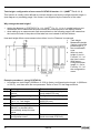
Dead zone: configuration of user menu PCSTAR 2 function 1.1.2 (HART Fct. 2.1.1.4)
The top dead zone is the minimum measuring distance between the gauge flange facing (the
reference point) and the product. The various probes for the BM 102 have differing top dead
zones and these are given in section 5.2.3: Probe measurement limits.
Why is configuration of the dead zone important?
The gauge will not display measurements taken here – the reading is blocked on reaching this
zone. This will avoid the gauge confusing the true level with a parasite (i.e. flange) as the product
nears the tank fitting and thereby displaying a false reading. It should be noted that although the
reading is frozen, the gauge will continue to follow the reflection. The PCSTAR 2 F8-marker menu
will display “Tank full” in this zone.
What is the difference between these functions:
®
PCSTAR 2 Fct 1.1.2/ HART Fct. 2.1.1.4: Dead zone
®
PCSTAR 2 Fct 1.5.1/ HART Fct. 2.1.5.3: Detection delay?
The “detection delay” function masks all signals (i.e. none are detected by the gauge) up to a
defined distance from the flange facing. The detection delay zone size is never greater than the
dead zone size. The PCSTAR 2 F8-marker menu will display “Tank full” and “Level lost” in this
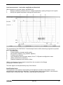
zone. This is illustrated below – the value in the box is the displayed value:
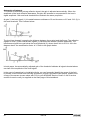
1
2
3
4
5
6
7
Height of tank fitting
Detection delay
(Fct.1.5.1=120mm)
Dead zone limit
(Fct.1.1.2=150mm)
Emitted signal
Flange reflection
(masked)
Masked zone (all
signals here are
ignored)
Level reflection
outside dead zone –
true level displayed
8
Level reflection inside
dead zone – level at
dead zone limit
displayed (frozen)
9
Level reflection inside
detection delay zone
– not detected by
gauge and level at
dead zone limit
displayed (frozen)
*(3) = 8850 mm - dead zone configured limit in terms of level
BM 102
35
How to set an analogue current output scale
User menu functions 1.3.1 to 1.3.4
This set of functions allows users to set up a scale. The minimum (4mA) and maximum (20mA)
values of an analogue current output should ideally lie within the device’s active measuring zone,
as the device will freeze when the signal is lost.
Refer to the measurement limits table for each probe type in the introduction. Refer also to the
start of section 3.3.3 for the advantages of changing tank height.
Example procedure 2 (using PCSTAR 2):
To personalise a measurement scale
• select “Level” as the current output parameter for the scale to be set up from the tank bottom
• select 4 … 20 mA current range with an error output at 22 mA
• choose suitable minimum and maximum values for the scale.
Step
1
Action
Press F2 to connect to the device
2
3
Press F2 to enter configuration menu
Scroll down the screen and click on
the data set field for Fct. 1.3.1:
Current 1 item. This will reveal a
scroll menu.
Use mouse to scroll down data set
field. Click on the new value.
Scroll down to Fct. 1.3.2: Current 1
range and click on data set field. This
reveal a scroll menu.
Use mouse to scroll down data set
field. Click on the new value.
Scroll down to Fct. 1.3.3: Scale I1 min
and click on data set field.
Enter the new value. This will give the
level that corresponds to the
minimum output of 4 mA.
Scroll down to Fct. 1.3.4: Scale I1
max and click on data set field.
Change to 8850 mm. This will give
the level that corresponds to the
maximum output of 20 mA. (and sets
max. output at the top dead zone
limit)
Press F6-Send to BM102 to
immediately update the device
configuration.
Press F3-Exit to quit the configuration
menu screen.
4
5
6
7
8
9
10
11
12
Data entered / value set
Tank status screen displayed (level reads
5650 mm)
Configuration menu displayed
This field currently reads “distance”
This field now reads “level”
This field currently reads “4-20 mA”
This field now reads “4-20 mA / E = 22 mA”
This field currently reads “0000 mm”
This field now reads “1000 mm”
This field currently reads “6000 mm”
(std. default: 6000 mm)
This field now reads “8850 mm”
n/a
Tank status screen displayed (level reads
5650 mm)
Setting up a volume table
Refer to procedure 3.
36
BM 102
How to configure the gauge to give volume readings
®
User menu PCSTAR 2 function 1.7.2 (HART submenu 2.1.7)
•
•
•
•
To be able to measure the volume, a conversion table (strapping table) will need to be created
using the PCSTAR 2 program or the HART® communicator.
The strapping table assigns defined volumes to the various levels.
In the case of non-symmetrical tanks, e.g. tanks with dished bottom, the accuracy of
volumetric measurement will depend on the number of entered “level/volume pairs”. The
maximum number of pairs (points) that can be set is 20. The volume is linearly determined
(interpolated) between 2 points.
The conversion table is generally used for volume, but can also be used for mass and flow.
Five points have been set in the following example.
Procedure 3: creating a strap table the probe by assigning a volume to a user-defined level
(using PCSTAR 2)
Step
1
2
3
4
5
6
7
8
Action
Connect to the gauge as described in section 3.3.1.
Press function key F2 or left click on F2-connection at
the bottom of the window. This will open the user
configuration menu.
Go to user function 1.1.1: Tank height to enter value
(click on field and type in value)
Go to user function 1.1.2: Dead zone to enter blocking
distance value.
Go to user function 1.1.6: Probe length to enter value
Go to user function 1.2.4: Length Unit to select length
units.
Go to user function 1.2.5: Volume unit to select volume
units
Go to user function 1.7.2: Input table. A maximum of 20
points can be entered. For each point a level and a
volume must be entered. Each point should have a
value higher than preceding one.
Input table
Point
Level
1
0.0 m or 0.0 ft
2
0.20 m or 0.66ft
3
0.75 m or 2.46ft
4
1.00 m or 3.28ft
5
5.60 m or 18.37ft
*Max. level
Data entered/value selected
n/a
n/a
6.00 m or 19.69 ft*
0.40 m or 1.31 ft*
5.80 m or 19.03 ft*
m or ft
m³ or ft³
See table below
Volume
0.0 m³ or 0.0 ft³
0.5 m³ or 17.66 ft³
1.0 m³ or 35.31 ft³
1.5 m³ or 52.97 ft³
16.8 m³ or 593.3 ft³
= tank height – dead zone
= 6.00 m – 0.40 m or 19.69 ft – 1.31 ft
= 5.60 m or 18.37 ft, equivalent to a volume of 16.80 m³ or 593.3 ft³
Note:
The level can effectively be measured between 0.20 m or 8” and 5.60 m or 18½ ft. When the
product level drops below the tip of the probe, the BM 102 will indicate that there is still remains of
0.20 m or 8”. Accordingly, the BM 102 can only indicate a level between 0.20 m or 8” and 5.60 m
or 18½ ft, since it only measures along the probes. The size of the dead zone depends on the
installation and on the probe type.
BM 102
37
Supplementary procedure for setting the 4 … 20 mA current to output volume readings
(using PCSTAR 2)
Step
1
2
3
4
5
6
Action
Go to user function 1.3.1 ”Current 1 item” to select
measurement function.
Go to user function 1.3.2 ”Current 1 range” to set fault
status
Go to user function 1.3.3 “Scale I1 min” to enter
volume value for the minimum output (4 mA)
Go to user function 1.3.3 “Scale I1 max” to enter
volume value for the maximum output (20 mA)
Either save the new configuration to disk by leftclicking on F5-Save to disk and download it onto the
BM 102 using the F6-Send to BM102 key.
Press F3 to exit the configuration menu.
Data entered/value selected
Volume
4 … 20 mA
0.50 m³ or 17.66 ft³
16.80 m³ or 52.97 ft³
n/a
n/a
3.3.4 HART® Communicator: installation & operating instructions
®
Display and configuration can also be carried out with a HART communicator. Operator control via
the separate HHC is described in detail in the operating instructions supplied with the HHC.
Basic instructions for taking measurements
Communicator layout
1
2
3
4
Two-pin jack for loop connectors
LCD
Function keys (F1 … F4)
Action keys
On/off
LEFT
Arrow
UP
Arrow
DOWN
Arrow
n/a
RIGHT
Arrow
Other functions:LEFT Arrow: Previous menu key
RIGHT Arrow: Select key
38
BM 102
Wiring, standard (non-Ex)
Caution
Refer to the HHC manual for wiring instructions when in an explosive atmosphere.
Displaying readings
Use the UP and DOWN arrows to move to the correct line and then select with the RIGHT Arrow.
1
HART Communicator
1
Offline
2 →
Online
3
Frequency Device
4
Utility
F1
3
F2
F3
Main menu
2
BM102:00000 01
Online
1 →
<Process Var.>
2
<Config./Test>
3
<Access/Rights>
4
<Watch status>
5
<HART Variables>
SAVE
F1
F2
F3
F4
Online menu
4
BM102:00000 01
♥
<Measurements>
1 →
Lvl 878.00 mm
2
Dist 121.00 mm
F4
BM102:00000 01
<Process Var.>
1 →
<Measurements>
2
<Input/Outputs>
SAVE
HOME
F1
F2
F3
F4
Measurement & input and output functions menu
BM 102
HELP
SAVE
HOME
F1
F2
F3
F4
Measurement display function
39
®
Configuration: summary of user functions via HART Communicator HC 275
Reset default values are in bold type in the “Input Range” column. Refer to the HART® HC275
Communicator operating instructions for further operating details.
Function (Fct.)
1.0
PROCESS VAR.
1.1.0 MEASUREMENTS
1.1.1 LEVEL
1.1.2 DISTANCE
1.1.3 VOLUME
1.1.4
ULLAGE VOLUME
1.2.0
1.2.1
INPUTS/OUTPUTS
FUNCTION I
1.2.2
1.2.3
I
%
40
Input Range
Description
Level value.
Distance value.
Volume value if a strapping table is
programmed.
Ullage Volume value if a strapping
table is programmed.
Function associated to the current
output (Primary Variable).
Current output value (mA)
Percentage of PV range.
BM 102
Function (Fct.)
2.0
CONFIG./TEST
2.1.0 OPERATION
2.1.1.0 BASIS PARAMETER
2.1.1.1 TANK HEIGHT
Input Range
Description
Enter 0 up to
60000 mm or 2362”
As per order
2.1.1.2 PROBE LENGTH
Enter 0 mm up to
< 24000 mm or
1063”
As per order
Tank height.
The tank height is defined as the
distance between the bottom of the
tank and the lower flange surface.
This value has to be equal to the
exact length of the probe. The only
situation for changing this value is if
the probe length has been changed.
2.1.1.3 TIME CONSTANT
Enter to
100 seconds
5 seconds
The time constant allows filtering of
possible signal fluctuations when the
product surface is turbulent.
2.1.1.4 DEAD ZONE
Enter a value
Fct.1.5.1(Detection
delay) … probe
length.
• Twin probe with
Probe length
<1 m or 3.3 ft
0.2 m or 8 in
• Single probe or
twin probe with
probe length
>1m or 3.3 ft
0.4 m or 16 in
• Coaxial probe
0 m or 0 in
Measurements near the flange may
not be precise or reliable.
Measurement may not be precise in
an area less than this recommended
value, depending on the probe type.
= Probe length
=0
= 1 mm or 0.04”
Read only Menu. Upper sensor limit.
Read only Menu. Lower sensor limit.
Read only Menu. Sensor minimum
span.
Select m, cm, mm,
inch, Ft, optional
unit
mm
Length unit of displayed value (level /
distance).
The optional unit allows the user to
define a new unit (name and factor)
see menu 2.1.2.1.3
Number of decimal places. Defines
the displayed length values format
(option of the HART® communicator
H275).
Warning : Critical Parameter
2.1.1.5
SENSOR INFO
2.1.1.5.1 Sensor upper limit
2.1.1.5.2 Sensor lower limit
2.1.1.5.3 Sensor min. span
2.1.2.0 DISPLAY
2.1.2.1 LENGTH
2.1.2.1.1 LENGTH UNIT
2.1.2.1.2 DISPLAY FORMAT
0, 1, 2, 3, 4, 5,
exponential format,
auto
2
BM 102
41
Function (Fct.)
2.1.2.1.3.0 DEFINE NEW UNIT
2.1.2.1.3.1 UNIT NAME
Input Range
Description
4 ASCII characters
“unit”
2.1.2.1.3.2 UNIT FACTOR
Enter 0.0 to
100000
1.0
Optional unit name. User has to enter
the unit name before using it in the
menu “LENGTH UNIT”.
Optional unit factor. User has to enter
the Unit Factor before using it in the
menu “LENGTH UNIT”.
With a factor 1.0, the unit is
equivalent to one millimeter.
With a factor 1000.0, the unit is
equivalent to one meter.
2.1.2.2.0 VOLUME
2.1.2.2.1 VOLUME UNIT
2.1.2.2.2 DISPLAY FORMAT
2.1.3.0 ANALOG OUTPUT
2.1.3.1 FUNCTION I
2.1.3.2 RANGE I
Select m3, l, US
Gal, Ft3, bbl, M3/h,
Ft3/h, kg, Metric
Tons, US Tons
m³
0, 1, 2, 3, 4, 5,
exponential format,
auto
2
Unit for conversion values ("volume
table").
The selected unit is only used to
display the conversion value from the
strapping table.
Number of decimal places. Defines
the displayed volume value format.
(Option of the HART® communicator
H275).
Select Level,
Distance, Volume,
Ullage Volume
Level
Select 4-20 mA or
4-20 mA + 22 mA if
error
4-20 mA
Current output function (measured
value to be displayed). Volume
functions will appear if a volume table
exists in menu 2.1.7.0
Current output range 4 … 20 mA (1st
choice). When the BM 102 is in error
mode, the current output is frozen
except if the second choice is
selected and then the current output
is fixed at 22 mA.
This menu is available in case the
range I menu is set to 4-20 mA with
error 22 mA.
This parameter sets the delay before
the current output goes to 22 mA
after the error mode occurred.
Input the lower range value
(corresponding to 4 mA) depending of
the parameter 2.1.3.1 chosen.
Input the upper range value
(corresponding to 20 mA) depending
of the parameter 2.1.3.1 chosen.
2.1.3.3 ERROR DELAY
Select No delay, 10
s, 20 s, 30 s, 1 mn,
2 mn, 5 mn, 15 mn
No delay
2.1.3.4 SCALE I
min. 4 mA
Enter 0 to Scale I
max.
As per order
Enter Scale I min to
tank height
As per order
2.1.3.5 SCALE I
max. 20 mA
42
BM 102
Function (Fct.)
2.1.4.0 USER DATA
2.1.4.1 TAG
2.1.4.2 SERIAL NUMBER
Input Range
Description
00000 01
Tag number of device.
Read only menu. Each device has its
own serial number.
Read only menu.
This number is factory set. Refer to
this number in case of warranty or
service claims.
Read only menu.
This number is factory set. Refer to
this number in case of warranty or
service claims.
Read only menu.
Release number of the device
(Software and Hardware version).
Read only menu.
Probe type attached to the flange.
2.1.4.3 FRENCH
COMMISSION
NUMBER
2.1.4.4 GERMAN
COMMISSION
NUMBER
2.1.4.5 RELEASE NUMBER
2.1.4.5 PROBE TYPE
Rod, Twin Rod,
Cable, Cable
+counterweight,
Cable without
counterweight,
Twin Cable, Twin
Cable +
counterweight,
Coax, Special 1,
Special 2, Special 3
As per order
2.1.4.5 CHECKSUM
Read Only menu.
Similar to the release number. This
parameter allows to identify the
software version of device.
BM 102
43
Function (Fct.)
2.1.5.0 APPLICATION
2.1.5.1.0 THRESHOLD
2.1.5.1.1 LEV. PULSE AMP.
Input Range
Description
Read only value.
2.1.5.1.2 LEV. PULSE GAIN
Read only value.
2.1.5.1. THRESHOLD
Enter a value from
50mV to 25000mV
500 mV G3 at 1 m
2.1.5.2 DISTANCE INPUT
Enter a value from
Fct. 2.1.1.4: Dead
zone to fct. 2.1.1.2:
Probe length
Dynamic value.
Amplitude of level pulse in millivolts.
Dynamic value.
Amplification of level pulse (gain 0, 1,
2, or 3).
Threshold of the level pulse (in
millivolts). The threshold evolves in
terms of gain amplification factor
changing by the electronic converter.
This function forces the BM 102 to
search for the product surface in a
zone other than the actual measuring
zone. If there is no level signal, you
can enter an estimated value.
2.1.5.3 DETECTION DELAY
Enter a value 0mm
or 0in to Fct.
2.1.1.4: Dead zone
As per order
This function forces the instrument
not to analyse reflections in a zone
directly below the flange. The entered
value of the detection delay must be
smaller than the "dead zone" value.
2.1.5.4 SEARCH PROBE END
The search zone
for the probe end is
from Fct 2.1.5.3
Detection delay up
to Fct. 2.1.1.1 Tank
height.
Automatically measures the probe
length. The tank must be empty. Tak
height must be configured to a value
greater than the estimated probe
length. Measured in the units
configured in fct. 2.1.2.1.1.
Restarts the BM 102.
Enter 0 to 15
0
Sets the address of the device for
connection to a HART multidrop
network. The current output switches
to 4 mA.
0 = 4 … 20 mA output current active
1 – 15 = in multidrop mode (4 mA)
Select m3, l, US
Gal, Ft3, bbl, M3/h,
Ft3/h, kg, Metric
Tons, US Tons
Liter [l]
0 to 20 points
0
(i.e. no volume
table)
Unit for conversion values ("volume
table"). The selected unit is used to
define the strapping table values.
2.1.5.5 RESET BM 102
2.1.6.0 SERIAL I/O
2.1.6.1 ADDRESS
2.1.7.0 STRAP TABLE
2.1.7.1 VOLUME UNIT
2.1.7.2 INPUT TABLE
2.1.7.3 DELETE TABLE
44
BM 102
This function defines the strapping
table. The maximum number of points
is 20. Each subsequent value must
be greater than the previous one. The
length and volume units can be
changed later without affecting the
settings in the table. Calculations are
done automatically in the instrument.
This function deletes the strapping
table.
Function (Fct.)
2.2.0 TESTS
2.2.1 TEST OUTPUT
2.3.0
SERVICE
3.0
3.1
ACCESS RIGHTS
MAINTENANCE PSW
3.2
SPECIALIST PSW
4.0
WATCH STATUS
5.0
5.1
HART VARIABLES
MANUFACTURER
Input Range
Description
Select 4 mA, 20
mA, Other
This function allows the current
output to be tested.
The output can be set to one of the
listed values. With a reference
ammeter, the calibration of the
current output can be verified.
Restricted access factory
configuration menu. These
parameters may be accessed via
Fct. 3.2 “Specialist PSW
(password).
Yes or no. Enter 9character code if
“Yes”.
No
Disables the access lock on the
configuration menu.
The password must contain exactly 9
characters.
E, R or U are used only. The
password is displayed in a scrambled
format. It allows KROHNE to decode
the password in case it was forgotten.
Specialist access to the Service
Parameters.
See KROHNE
Service centre or
BM 102 Service
Manual for code.
Displays the status of the device.
®
Read only menu.
KROHNE
5.2
MODEL
Read only menu.
BM 102
5.3
FLD DEV REV
Field device revision.
Read only menu.
Software revision.
Read only menu.
Hardware revision.
Read only menu.
Read only menu. The device ID is
also the serial number of the device.
32 bytes of ASCII characters
16 bytes of ASCII characters.
Equivalent to PCSTAR2 Fct. 1.4.8
Month Day Year (xx / xx / xx).
Number of preamble in the response
frame of the device.
Tag name of the BM 102.
Address of the device.
1.0
5.4
SOFTWARE REV
5.5
HARDWARE REV
5.6
DEVICE ID
5.7
5.8
MESSAGE
DESCRIPTOR
5.9
5.10
DATE
NUM RESP PREAM
5.11
5.12
TAG
POLL ADDRESS
1.0
1.0
BM 102
45
3.3.5 Characters available for alpha-numerical data functions in PC STAR 2 and on the
®
HART console
This concerns the following functions:
PCSTAR 2
fct. 12.6.1: Unit name, fct. 1.4.4: Device number, fct. 1.4.8: Option
®
HART console (HHC)
fct. 5.7 Message, fct. 5.8 Descriptor, fct. 5.11 Tag
@
A
B
C
D
E
F
G
46
H
I
J
K
L
M
N
O
P
Q
R
S
T
U
V
W
X
Y
Z
[
\
]
^
_
Space
!
“
#
$
%
&
‘
BM 102
(
)
*
+
‘
.
/
0
1
2
3
4
5
6
7
8
9
:
;
<
=
>
?
3.3.6 Local user display (instruments equipped with DIN connectors only)
The BM 102 local indicator is available as an option. This fits onto the BM 102’s standard DIN
connector. Data can be read from an LED display. The gauge configuration menu cannot be
accessed with this option. For non-Ex applications only. Please refer to the DA 06 Supplementary
instruction manual for further information.
Technical data: DA 06 Plug-in Display (non-Ex)
DA 06 Plug-in display (supplied separately)
Measuring range:
Display:
Accuracy:
Adjustable parameters:
Min. / max. value memory:
Housing:
Protection:
Temperature range (ambient)
Electronic system:
Storage:
Electrical connection:
Input signal
Max. voltage drop over unit
Switching output1
CE conformity
DA 06 Plug-in display mounted on BM 102 gauge
-1999 to 9999 digits (min. and max. values user defined)
4-digit, 7.6 mm or 0.3” high, red LED display, display housing
can be turned through 330°
0.1 % +/- 1 digit
Scaling, decimal point, attenuation, switching point, delay
Displays the minimum and maximum values recorded during
operation.
Plastic, PA 6.6 / polycarbonate 47mm X 47mm x 68 mm or 1.9” x
1.9” x 2.7” (h x w x d), housing can be turned by 300°
IP 65 (EN 60529)
0°C … +60°C or 32°F … 140°F
-30°C … +80°C or -22°F … 176°F
Adapter for plug as per DIN 43650
4…20 mA / 2-wire
Approximately 6 V DC
open collector (PNP),
max. 125 mA,
on and off delay: 0 to 100 seconds,
temperature influence: 0.1% / 10 K
EN 50081-1 and EN 50082-2
BM 102
47
3.4
BM 102 MICROFLEX T.D.R. meter characteristics
This subsection explains:
• the four principle configurations for setting up a measurement scale and what the user should
be aware of in each case;
• what happens when the tank is full or empty;
• what is the level threshold and how to modify it and
• what happens when level is measured when more than one product in the tank;
The measurement scale: five possible configurations for analogue current output – with
“Level” selected in PCSTAR 2 function 1.3.1: Current 1 Item
A
B
C
D
E
Tank height (Fct. 1.1.1)
Probe length (Fct. 1.1.6)
Detection delay (Fct. 1.5.1)
Non-measurable zone
Minimum distance between nonmeasurable zone and dead zone
(Fct.: 1.1.2 – Fct.: 1.5.1)
F
G
H
Upper dead zone (Fct. 1.1.2)
Optimal measuring range
Reference point at tank bottom
Fct.: 1.3.1 = Level
The configurations described below are illustrated in the above diagram:
(1) The “current output” range is smaller than the optimal measuring range.
(2) The “current output” range is equal to the optimal measuring range:
Scale min.: 4 mA (Fct. 1.3.3) = tank height – probe length
Scale max.: 20 mA (Fct. 1.3.4) = tank height – dead zone
(3) The “current output” range is greater than the optimal measuring range:
Scale min.: 4 mA (Fct. 1.3.3) = 0.0
Scale max.: 20 mA (Fct. 1.3.4) = tank height – dead zone
(4) The “current output” range is greater than the optimal measuring range:
Scale min.: 4 mA (Fct. 1.3.3) = tank height – probe length
Scale max.: 20 mA (Fct. 1.3.4) = tank height
(5) The “current output” range is greater than the optimal measuring range:
Scale min.: 4 mA (Fct. 1.3.3) = 0.0
Scale max.: 20 mA (Fct. 1.3.4) = tank height
NOTE:
The reference point for distance measurements is the bottom of the flange face.
48
BM 102
3.4.1 Gauge operating logic when the reflection is lost
The product reflection pulse is usually lost when the level is in the top dead zone or near the
bottom of the tank. The diagram below shows the action taken by the gauge depending on where
®
the last reflection was lost. Use PCSTAR2 F8-Marker display function or HART HHC Fct. 4.0
Watch Status to follow the measurement status of the gauge.
Zone 1 : Dead and detection delay zones
Marker “Tank full” and “Level lost” is displayed
when the product enters the dead zone and no
reflection is found. This will also occur once the
level reflection is within the detection delay
zone.
The gauge assumes the tank is full and
displays the maximum level value.
The gauge searches for a reflection along the
entire length of the probe.
Zone 2 : Full zone (& dead zone)
Marker “Tank full” is displayed in this zone.
If the gauge loses the signal in this zone, it
reacts as in zone 1: the tank is assumed to be
full.
The gauge searches for a reflection along the
length of the probe.
Zone 3 : Central measurement zone
The gauge searches along the length of the
probe for the largest pulse reflection.
If the pulse is lost the reading freezes at the
last value.
Marker “Level lost” will be displayed. The
probe will search for a reflection along the
length of the probe.
* if L > 2 m or 6 ¾ ft
Zone 4 : Empty zone
If the reflection is lost here then the gauge
assumes the tank is empty and marker “tank
empty” is displayed. The gauge searches for a
reflection in this zone but makes a search
along the entire length of the probe once every
minute.
The reading will remain frozen during this time.
BM 102
49
3.4.2 Gain and voltage amplitude
As explained in the measuring principle in section 6, the level of a product is converted from a
return signal (the product reflection) received by the gauge: this signal has taken a certain amount
of time to return to the gauge and it has a certain strength / size measured in milli-volts
(dependant on the dielectric constant of the product).
All pulse signals returning to the gauge electronics block (including flange, obstruction and the
product surface reflections) are converted to voltage amplitudes. The gauge’s microprocessor
looks for part of the largest signal that is over a set voltage amplitude, called the “threshold”, and
identifies this as the product being measured. For this signal to be usable by the gauge, the
microprocessor will amplify the signal by increasing the gain. Once the signal is within a set
“working” range, the gauge follows this signal. The gauge registers any changes in time for this
part of the signal to return to the converter and translate this into a displayed level or volume.
Gain is a function of voltage amplitude. This defines the default threshold value when the gauge is
searching for the product level. A strong return signal will be given a low gain (i.e. Gain 0 or a
small amplification). However, if the signal is very weak, then a Gain of 3 (i.e. high signal
amplification) is given.
Example of signal amplification:
50
BM 102
Level measurement: Level pulse amplitude and threshold
After connection to a power supply, the BM102 will:
1.
Measure reflection pulses in terms of voltage amplitude by cycling through a set of gains.
2.
Identify the highest amplitude as being the product level.
This screenshot of the PCSTAR 2 F7-Oscilloscope function while measuring a typical one product
application identifies:
1
Emitted pulse
2
Flange reflection (except coaxial probe)
3
Non-product reflection (e.g. parasite: agitator)
4
Product level reflection
5
Level threshold (with two-metre steps). Set in F11-Dynamic configuration menu
6
Offset (see below for definition)
7
Distance measured as a function of time
Offset is the distance for the signal to travel from the converter to the flange.
(the gauge’s reference point).
The level signal can be optimized by way of two factors:
Amplification factor
The amplitude of the signals is proportional to the dielectric constant of the product. At low
amplitudes the signal should be amplified. The amplification factor is dependent on the dielectric
constant and on the probe type. The device sets the gain automatically.
BM 102
51
The following factors apply to the set gain:
Gain
Amplification factor
0
1.05
1
2.10
2
4.37
3
8.93
Level threshold
The level threshold suppresses interference signals so that only the reflections from the product
surface (level signal) are shown. The factory setting of the level threshold is suitable for standard
applications. The threshold will need to be adjusted in the case of very low dielectric constants,
multiple interference reflections or unfavourable installation conditions.
The illustrations below show interference signals when the oscilloscope function is used. These
reflections can be due to various causes, e.g. tank internals or multiple reflections within the
measuring range.
Even though the interference signals
are very weak, the threshold should
nevertheless be set to a value above
these signals.
1
2
3
4
Emitted pulse
Flange reflection
Level signal
Interference signal
1
2
3
4
5
Emitted pulse
Flange reflection
Level signal
Interference signal
Threshold
In the diagram above it can be seen that the level of the threshold is not constant: 400 mV at 1 m or
3.3 ft, and only 250 mV at 10 m or 33 ft.
No attenuation is required at a probe length ≤ 3 m or 10 ft. The form of the threshold is dependent
on attenuation and is automatically adjusted by the device over the measured length.
52
BM 102
Setting the level threshold
If the level threshold is set too high, i.e. it is greater than the amplitude of the level reflection, the
device will not find any level even with maximum amplification.
If the level threshold is set too low, i.e. it is below the amplitude of some of the interference signals,
the device will identify and indicate one of these interference signals as a level reflection only if the
tank is empty.
Precise setting of the level threshold is especially important when the dielectric constant is low.
•
•
•
To set, the level (amplitude of the reflection) must be known.
The level threshold should be half-way between the invalid interference signals and the level
reflection signal.
The reflection from the probe tip, which is clearly identifiable at a low εr value, does not need to
lie below the level threshold.
Take a look at all the reflections over the entire probe length and then change the level threshold
and/or the amplification factor in the “Dynamic configuration (F11)” menu.
Typical signal trends
The following diagrams show characteristic signals that have been recorded with the oscilloscope
function.
Rod or cable probe with gain 1
Rod or cable probe with gain 2
Coaxial probe with gain 1
Coaxial probe with gain 2
The signal from coaxial probes does not include the flange reflection, due to the mechanical setup
which does not produce any change in impedance at the flange.
The amplitude of reflection from the product surface increases as the level rises and decreases as
the level falls.
BM 102
53
Automatic adjustment:
To maintain a sufficiently strong reflection signal, the gain is adjusted automatically. When the
amplitude of the level reflection decreases, the gain will increase to compensate for the loss in
signal amplitude. Gain and level threshold thus maintain the same proportion.
At gain 3, the level signal (1) is located between a distance of 2 and 4 metres or 6.5 and 13 ft. (2) is
the level threshold. This is shown below:
The level has dropped, increasing the distance between the product and the flange. The reflection
signals for level (1) and interference signals (3) have become weaker (smaller amplitude). The
interference signals are now below the level threshold (2), whose lower limit is 50 mV. As in the
diagram above, the amplification factor is 3. Refer to the graph below:
In both cases, the automatically adjusted gain of the threshold indicates all signals located above
one-half of the amplitude of the level signal.
In the event of operational or installation faults, you can frequently identify the cause of the fault
by means of this function and normally eliminate it yourself. Should the fault persist, please send
a copy of the screen (screen shots with F10) to your KROHNE Service Centre. A list of service
centres for each country is supplied on the back page of this handbook.
54
BM 102
Procedure (example where the level measured is too low compared to true level)
• read off displayed peak amplitude using the oscilloscope function – F7
• modify level threshold value
Step
Action
1
2
Execute PCSTAR 2. Press F2 to connect to gauge.
Press F11 to open F11-Dynamic configuration
window.
The top of the window gives the distance, peak
amplitude in volts and gain.
3
4
5
6
7
The configured level threshold is listed under peak
amplitude in mV. Click on the “Modify” box to activate
the “Threshold” field.
Click on the ”Threshold” field and enter the new
value.
If the approximate level is known, click on the
“Distance” field and then click on the “Search” button
If the value is still too low, try reducing threshold
again by small amounts. If this does not resolve the
problem, contact the KROHNE Service Centre. . A list
of service centres for each country is supplied on the
back page of this handbook.
Data entered/ value
displayed
n/a
n/a
21000 mm
650 mV
Gain 3
n/a
500 mV
n/a
Note that the threshold drops every 2 metres or 6.5 feet.
Solid application notes
Most dry solid applications except powder or flakes with high dielectric constants, such as coal
powder, are measured with a Gain of 3. If it is difficult to measure level at a certain point with the
gauge using a Gain from 0 to 2, then an internal tank structure (exposed girder, etc.) is most likely
to be within the electromagnetic pulse field area: the gauge will detect the largest signal and
assume this is the product level.
BM 102
55
3.4.3 Level measurement when more than one phase or layer in the tank
Level can be measured with more than one phase in the tank. This requires setting a parameter in
the factory menu (Fct. 1.1.3: Application Type) to the following measurement mode:
for measuring level with two or more phases
• 2 liquids, 1 level
for measuring one phase or liquid
• 1 liquid, 1 level
Characteristics
• The level of the top product can be detected if it has a minimum layer of approximately
100 mm – when measuring a top product with a dielectric constant of 2.4.
• The mode “2 liquids, 1 level” permits level to be measured even when more than 2 liquids are
present in the tank.
• The first return signal is identified as being level and the second is ignored.
• This mode may be used with all probe types.
Example application 1: level measurement of oil (1 liquid in the tank)
With Factory Menu Fct. 1.1.3:
Application Type set to 1 liquid, 1
level, the BM 102 will search for the
return signal with the highest
amplitude (i.e. higher than the
threshold). It will measure the oil
level.
1
Level measurement signal
2
Threshold
Example application 2: level measurement when there are 2 liquids (oil/water) in the tank –
using a correctly configured gauge
With Factory Menu Fct. 1.1.3:
Application Type set to 2 liquids, 1
level, the BM 102 will search for the
first return signal higher than the
control threshold. It will correctly
measure the oil level (i.e. “level”).
1
Level signal
2
Threshold - finds first signal
3
Oil-water interface signal
For further information, please
contact your local KROHNE Service
Centre. Contact details are supplied
on the last page of this manual.
56
BM 102
4
Service / Maintenance
Maintenance is normally not required in standard applications. However, heavy deposits on the
probe can cause measurement deviations or faulty operation. The measuring system is
comprised of:
• a signal converter,
• a probe,
• seals and
• a process connection.
4.1
Replacement of the signal converter
BM 102 servicing by the customer is limited by warranty to the removal and replacement of the
housing containing the potted signal converter. Other repairs must be done by KROHNEauthorized service staff. For safety reasons, the signal converter must be detached from the
flange system under atmospheric conditions.
Before changing the converter and its housing:
• Disconnect gauge from the power supply before servicing.
• Ensure that the tank is at atmospheric pressure before servicing.
• Do not, under any circumstances, remove the locking ring (circlips), item A,
shown below – this is a critical pressure-bearing component:
BM 102
57
1
2
3
4
Signal converter housing
O-ring, grease well before fitting
Lock washer
Housing (socket head cap) screw x 4
(M5 x 12), non-pressure-bearing
Procedure to replace the signal converter (refer to diagram above)
Step
Action
1
Disconnect all wires (see sections 2.1.2 or 2.1.3)
2
Unscrew the 4 socket head cap screws M5x12 (ISO 4762), item 4, using a 4 mm
Allen/hexagon key) and remove the signal converter.
3
The gasket between signal converter and flange must be well greased.
4
Install the new signal converter and making sure that the signal pin in the
housing is not damaged.
5
Reinsert and tighten up the 4 socket head cap screws M5x12, item 4.
6
Reconnect all wires as described in sections 2.1.2 or 2.1.3.
Hazardous-duty systems
Before replacing the signal converter in hazardous locations, make absolutely sure
that there is no risk of explosion (gas-free certificate). For further information refer
to the BM 102 MICROFLEX KEMA 00 ATEX 1101X Supplementary Installation
and Operating Instructions. This document is available from the “Download Centre”
on KROHNE’s website http://www.krohne.com/.
For pressurized tanks with a flange connection between the tank and the device,
do not undo the 4 flange bolts - these are used for fastening the complete sealing
system.
58
BM 102
4.2
Fault clearing
Event
Error messages
“Tank full” status marker on*,
reading frozen at max. or min.
value
“Tank empty” status marker
on*, reading frozen at max. or
min. value
“Tank full” and “Level lost”
status marker on*, reading
frozen at max. or min. value
“Level lost” status marker on*,
reading is frozen
“Reference not found” status
marker on*
“Level lost” and
“Reference not found” status
markers on*, reading frozen
Fault
Action
No fault. The level has
reached (and possibly risen
above) the top configured
measurement limit and is
either displaying the maximum
(when measuring level) or
minimum (when measuring
distance) output.
No fault. The level has entered
the gauge’s bottom dead zone
and can no longer detect a
return signal. Either the
maximum (when measuring
distance) or minimum (when
measuring level) output is
displayed.
No fault. The level has entered
the gauge’s top dead zone
and can no longer detect a
return signal.
The instrument has lost the
level signal, has searched but
not yet found the return pulse.
This may occur if the pulse
has dropped below the
threshold. Parasite signals
from the flange or obstructions
in the tank may render the
gauge unable to identify the
correct signal.
Occurs when there is a
problem with the time base on
the HF board.
The probe has received an
electrostatic discharge.
None. Measurements should
be normal once the level is in
the configured measurement
range.
None. Measurements should
be normal once the level is in
the configured measurement
range.
Empty the tank below the top
measurement range limit and
check the measurement.
Ensure that tank is emptied
below maximum level and
check the measurement.
If the signal is not detected
then modify the control
threshold manually as shown
in sections 3.5.2 and 8.4.2
using the oscilloscope (F7)
and dynamic configuration
(F11) windows in PCSTAR 2.
Please contact your local
KROHNE Service Centre**.
The gauge will search for the
level again and resume
readings. If the reading
remains frozen then the signal
converter may have been
damaged by ESD and may
need replacing. Please
contact your local KROHNE
Service Centre**.
* Gauge connected to PC-STAR 2 software or HART Handheld Controller (HHC) with Marker
status window (F8) or list displayed
** KROHNE service centre contact details are supplied on the last page of this handbook.
BM 102
59
Event
“Flange not found” status
marker on*
“Delay out of limits” status
marker on*, reading is frozen.
“Negative voltage error” status
marker on*
“VC01 voltage error ” status
marker on*
“VC02 voltage error” status
marker on*
“Reprogramming FPGA”
status marker on*
Fault
The signal converter has been
incorrectly configured to
measure with a cable or rod
probe when it is equipped with
a coaxial probe. This may also
due to installation on a long
nozzle which has the effect of
attenuating the flange pulse.
The emitted pulse has not
been detected. The gauge will
not work until it has been
found.
Occurs when there is a
problem with the time base on
the HF board.
Action
Contact your local KROHNE
Service Centre for the
corrective procedure**.
The signal converter may
need replacing. Please
contact your local KROHNE
Service Centre**.
Please contact your local
KROHNE Service Centre**.
* Gauge connected to PC-STAR 2 software or HART Handheld Controller (HHC) with Marker
status window (F8) or list displayed
** KROHNE service centre contact details are supplied on the last page of this handbook.
60
BM 102
Event
General operation
Instrument is not accurate
with a product that has a
high dielectric. A constant
offset is observed when
taking measurements.
Fault
Action
Tank height is not correct.
Check current output and tank
height parameters.
If the signal converter has been
replaced, verify that factory
calibration parameters are still the
same. Ask KROHNE** for the
factory calibration sheet (if not
supplied) and the password for
access to the factory menu.
Check the tank for obstructions and
verify that the probe is clean.
In the case the indicated level is
close to the nozzle, increase the
detection delay and the dead zone
with the same ratio or increase the
threshold level if the full
measurement range is essential.
In any case use the PC STAR 2
oscilloscope function to visualise
and to analyse the application.
The threshold level must be
adjusted so that it masks the
disturbances. It also gives enough
margin for detection of the level
pulse.
Very large pulses along the
measurement signal (same
amplitude as the initial pulse) can
be caused by a probe which is
touching the nozzle or the tank side
(see section 1.3.5). Ensure that no
contact is possible.
Contact KROHNE** for the
corrective procedure or refer to the
Service Manual.
Check that Factory Menu function
1.1.3: Application Type is set to
“2 liquids, 1 level”.
Check also that there is a layer of
more than 100 mm of top product
above the bottom product.
The BM 102 indicates an
incorrect level value.
The BM 102 measures a
non-valid reflection.
Instrument is not accurate
when there are two or more
phases in the tank.
The instrument may be
incorrectly configured for this
type of application i.e. it is
measuring the interface
instead of the level.
** KROHNE service centre contact details are supplied on the last page of this handbook.
BM 102
61
Event
Fault
Electrical Connections and Communication Output
Current Output value < 4 mA.
No power supply.
Connection of the device is
incorrect.
The calibration of the current
output is incorrect.
Reads 22 mA.
An error has occurred.
The device is in its start-up
phase.
The value at the current output
does not correspond to the
value at the display (PC STAR
2 or HART® communicator).
The current output settings are
incorrect.
Data communication via the
digital interface is not working.
The BM 102 is in its start up
phase, wait 50 seconds and
try again.
The communication
parameters of the computer
are set incorrectly.
Bad connection to the
interface.
Current output value is
< 4 mA.
Current output value is
= 22 mA
Action
Check the power supply
Check the connection
between the device and the
power supply.
Execute the calibration if you
have authorized access or
contact KROHNE Service
centre**.
This happens in case the
range 4-20 mA / error 22 mA
is selected.
Check the status of the device
by selecting the marker
window (F8) or enter the
status (4.0) menu of the
®
HART communicator.
Wait 50 seconds. If the current
value drops to a value
between 4 and 20 mA, and
goes immediately back to
22 mA, contact your KROHNE
Service Centre**.
Check the current loop and
the connections.
Configure the output as
described in Sect. 3.3.3 (user
sub-menu 1.3) of the BM 102
Handbook – also try adjusting
the threshold using F11Dynamic Configuration
function (PCSTAR 2) or menu
2.1.5.1.0 (HHC).
Check computer setting
(address/device number).
Check connection.
Contact your KROHNE
Service Centre**.
If problem persists then
contact your KROHNE Service
Centre**.
* This document is available from your local KROHNE Sales office or on the “Download Centre”
on KROHNE’s website http://www.krohne.com/.
** KROHNE service centre contact details are supplied on the last page of this handbook.
62
BM 102
5
Technical data
5.1
Technical data
Application
Range of applications
Function and system design
Measuring principle
Equipment architecture
Input
Measured variable
Measurement range
Blocking Distance
(dead zone)
Output
Analogue
Digital
Digital, Ex ia
Signal on alarm
Continuous level measurement of liquids, pastes, slurries and
powders
Time domain reflectometry
See section 5.2
Distance (between the reference point – gauge flange facing –
and the product surface), level, liquid interface & volume
Variable according to probe type, see Equipment architecture,
section 5.2.1
Variable according to probe type, see probe measurement limits,
see section 5.2.2
4 … 20 mA, passive output
Load
Passive outputs
750 ohms maximum
Error signal
22 mA
Temperature drift
25 ppm / K
Resolution
± 3 µA
HART®, passive output
HART®, passive intrinsically-safe output
Status markers via PC STAR 2 or HART® controller (HHC)
Performance characteristics
Accuracy
Level measurement
Liquids when probe length, L ≤ 15 m or 50 ft.
± 15 mm or 0.6 “ outside the dead zone
Optional: ± 5 mm or 0.2 “
Liquids when probe length, L > 15 m or 50 ft.
± 0.1% of the measured distance
Optional: ± 0.05% of the measured distance
Solids (powders)
± 20 mm or 0.8 “
with 4 … 20 mA current output
± 0.01% of the measured distance
Reference operating conditions
Ambient temperature
+20°C ± 5°C or +68°F ± 9°F
Ambient air pressure
1013 mbar abs. ± 20 mbar or 14.69 psig ± 0.29 psi
Relative air humidity
60% ± 15%
Reference target
- coaxial probe :
water surface
- single probe :
Ø 0.8 m or Ø 31.5 in. metal plate
- twin probe :
metal block “short circuit”
Free space diameter
> 300 mm * or 11.81” *
Distance to obstruction
> 1 m or > 3.28 ft.
* not necessary for coaxial probe.
BM 102
63
Repeatability
Hysteresis
Resolution
Transient recovery time
± 2 mm or 0.08 “
none
± 1 mm or 0.04 “
The transient recovery time to 1% deviation from the final value
amounts to approx. 4.6 times the programmed time constant.
However, the transient recovery time may differ if changes in
level are very rapid.
Start-up time
≤ 23 seconds
Long term drift
The long term drift is within the specified error of measurement.
Allow for the thermal expansion coefficient in the case of liquids
(organic liquids: ~0.15%/K)
Influence of ambient temperature
®
typically 70 ppm/K
current output
HART :
measured value
Approx.25 ppm (max. deviation over whole measurement range).
atmosphere
-1 ppm/K (above the liquid product).
digital
No influence on measured value due to regular self-calibration.
Environment
Ambient temperature
Storage temperature
Environment class
Protection
Shock resistance
Vibration endurance limit
Power supply
Standard
Hazardous-duty (Ex, FM, …)
Range
Process
Process temperature, product
Process temperature, flange
Process pressure,
standard
-30°C … +60°C or -20°F … +140°F***
-40°C … +80°C or -40°F … +176°F
Locations exposed direct to open-air climate, D1
IP 65 / NEMA 4 – 4X
The device withstands the impact test in conformity with EN
61010, Section 8.2 with 0.5 J energy.
IEC 68-2-6 and prEN 50178
(10-57Hz: 0.075 mm / 57-150 Hz: 1 G).
24 V DC,
≤ 28 V DC
18 … 35 V DC
-30°C … +200°C or -22°F … +392°F * **
-30°C … +90°C or -22°F … +194°F,
option +200°C or 390°F**
-1 … 16 bar or -14.5 … 232 psig; max. 40 bar or 580 psig at
20°C or 45°F***
Minimum dielectric constant εr of product measured: probe type limits
Coaxial (type 3)
εr ≥ 1.4
Twin probe (type 4)
εr ≥ 1.8
Single probes (types 1, 2 & 6) εr ≥ 2.1
Human interface
Communication, standard
Operator control and data display via PC using PCSTAR 2
software or HART® handheld communicator
Point-to-point
1 gauge connected to a PC or HHC
Multi-drop
Up to 5 gauges connected to a PC or HHC
*
see BM 102 MICROFLEX KEMA 00ATEX1101X Supplementary Installation and Operating
Instructions for Ex values
** higher or lower temperatures on request (non-Ex)
*** Subject to the process temperature and the mechanical properties of the process connection
64
BM 102
Construction materials
Housing
Probe
Gasket
Spacers (on twin probes)
Aluminium with epoxy coating
Refer to section 5.2.1: BM 102 mechanical options
Viton, optionally Kalrez 6375
Refer to section 5.2.1: BM 102 mechanical options
Weight
Housing
Single rod Ø 8 mm
Single cable Ø 4 mm
Twin cable Ø 4 mm
Single cable Ø 8 mm
Coaxial
2 kg or 4.4 lb
0.41 kg/m or 0.28 lb/ft
0.12 kg/m or 0.08 lb/ft
0.24 kg/m or 0.16 lb/ft
0.41 kg/m or 0.28 lb/ft
1.3 kg/m or 0.87 lb/ft
Standards
Electromagnetic compatibility
directives followed for EU
countries
Other EU directives
The level gauge satisfies the protection requirements of :
Electromagnetic compatibility
Directive 89/336/EEC in conjunction with EN 61326-1(A1&A2)
and EN 61000-6-2 standards. It also respects the NAMUR NE
21/98 standard. Protection against EMC emissions is only
guaranteed when the device is used in metal tanks (except when
the device is equipped with coaxial probes).
Low voltage electrical equipment
Directive 73/23/EEC modified by Directive 93/68/EEC (art.13) in
conjunction with the EN 61010-1 standard.
ATEX*
Directive 94/9/EC in conjunction with EN 50014, EN 50020 and
EN 50284 standards.
Refer to the BM 102 MICROFLEX KEMA 00 ATEX 1101X
Supplementary Installation and Operating Instructions for further
information.
5.1.1 Accuracy
Due to the method of measurement, which primarily determines distance, the measuring accuracy
is specified only as a factor of distance. For that reason, all data in this section refers to the
measured distance.
Standard calibration
Error of measurement (mm)
Distance from flange (m)
BM 102
65
Special calibration
Error of measurement (mm)
Distance from flange (m)
5.1.2 Start-up characteristics
The current output stays at
22 mA for 15 seconds once
switched on.
The analogue output
subsequently indicates a
value between 4 and 20 mA
until the level has been
found.
After a maximum of
23 seconds, the current
output indicates the
measured level and
follows it.
66
BM 102
BM 102
SS 316 / 316L
Probe material
Liquid
SS 316 / 316L
Hastelloy C22
SS 316 FEP coated
DN50 PN 25/40
2” ANSI 150 lbs
1” G / 1” NPT
2.1
Ø600 mm
or Ø24 “
≤ 24 m or 79 ft.
* gauge with flange connection ** higher on request
SS 316L
Hastelloy C276
DN50 PN 25/40
2” ANSI 150 lbs
2” G / 2” NPT***
1.8
Ø200 mm
or Ø8 “
≤ 24 m or 79 ft.
Minimum process DN50 PN 25/40
connection
2” ANSI 150 lbs
1” G / 1” NPT
1.4
Ø0 mm
or Ø0 “
Free area (no
obstructions or
discontinuities)
Minimum
dielectric constant, εr
≤ 6 m or 20 ft.
Range, max.
Level
Single inner conductor Two flexible SS316 Single flexible cable
with protective tube. cables with spacers with countrerweight.
interspersed along its
length, with short
circuit and
counterweight.
Description
Single cable Ø4 mm
or 0.15” (Type 2)
Coaxial Øext. 28 mm Twin cable Ø4 mm
or 0.15” (Type 4)
or 1.1” (Type 3)
Probe
(Type code)
Liquid / Liquid Gas applications
*** on request
SS 316 / 316L
DN50 PN 25/40
2” ANSI 150 lbs
1½” G / 1½” NPT
2.1
Ø600 mm
or Ø4 “
≤ 24 m or 79 ft.
Single flexible cable
with counterweight.
Single cable Ø8 mm
or 0.3” (Type 6)
Powder
Hastelloy C276
PVDF coated (non-Ex)*
PVC coated (non-Ex)*
SS 316L
DN50 PN 25/40
2” ANSI 150 lbs
1” G / 1” NPT
2.1
Ø600 mm
or Ø24 “
≤ 3 m or 10 ft.**
Single rigid rod.
Single rod Ø8 mm
or 0.3” (Type 1)
5.2
5.2.1 BM 102 mechanical options (by probe type)
BM 102 equipment architecture
67
68
BM 102
** on request
None
Counterweight
(dimensions in
mm)
Gauge
illiustration
PTFE (if length
> 1.5 m or 5 ft).
Spacer material
Ø45 x 60 (316L)
Turnbuckle (316L)
FEP moulded onto
the cable.
Coaxial Øext. 28 mm Twin cable Ø4 mm
or 1.1” (Type 3)
or 0.15” (Type 4)
Probe
(Type code)
Ø25 x 100 (316L)
Ø25 x 100 (HC22)
Ø25 x 100 (HC276)
Chuck (316L)
Turnbuckle (316L)
No spacer.
Single cable Ø4 mm
or 0.15” (Type 2)
Liquid / Liquid Gas applications
None
No spacer.
Single rod Ø8 mm
or 0.3” (Type 1)
Powder
Ø12 x 100 (316L),
where L > 10 m
Ø45 x 245 (316L),
where L < 10 m
Turnbuckle (316L)**
Without**
No spacer.
Single cable Ø8 mm
or 0.3” (Type 6)
5.2.2 Definition of terms
Distance
Level:
Probe Length:
Tank Height:
Ullage (volume):
Volume:
Distance from the face of flange to the level (1 product) or the surface of
the top product (2 products).
Height from the bottom of the of the tank to the surface of the top product
(Tank height – distance).
Ordered length of probe, L1, from face of flange to end of probe (including
short circuit and counterweight).
Distance from the face of the flange to the bottom of the tank.
Unfilled volume.
Total volume filled.
BM 102
69
5.2.3 Probe measurement limits
A1, the top dead zone,
The minimum distance from the flange to the
top limit of the measuring range. The
measurement displayed on the gauge will
freeze below this distance and status markers
will indicate that the reflection has been lost.
A2, the bottom dead zone,
A length at the end of the probe where
measurement is not possible. For products with
very low dielectric constants (εr < 5), accuracy
may be affected in a non-linear zone up to
150 mm or 6” above the bottom dead zone, A2
D, the non measurement zone,
A zone where measurements cannot be taken
(i.e. the counterweight, turnbuckle, etc.*). The
measurement displayed on the gauge will
freeze to L2.
L1, factory configured probe length
Length to the end of the probe (excluding short
circuit or counterweight*). This parameter is
given in User Function 1.1.6: Probe length in
the User Configuration Mode.
L, with probe length
The length specified by the customer in the
order (including the counterweight).
Note : dead zone = blocking distance
*except the Ø12 mm x 100 mm or ؽ “ x 4” counterweight for the Ø8 mm or 0.3 “ single cable
probe
Warning:
Set PCSTAR 2 User Function 1.1.2 “Dead zone” in the gauge’s configuration mode
to at least top dead zone size as specified per probe type in the table below, so that
the gauge never displays product level within this zone. Refer to user function 1.1.2
in section 4.2 for more information.
Probe measurement limits
Top dead zone, Bottom dead
Top dead zone,
A1
zone, A2
A1
εr = 80*
εr = 80*
εr = 2.4*
Twin cable Ø4mm (4)
150mm or 6”
20mm or 0.8”
300 mm or 12”
Single cable Ø4mm (2) 300mm or 12”
20mm or 0.8”
400mm or 15¾”
Single rod (1)
300mm or 12”
20mm or 0.8”
400mm or 15¾”
Single cable Ø8mm (6) 300mm or 12”
20mm or 0.8”
400mm or 15¾”
Coaxial (3)
0mm or 0”
10mm or 0.4”
0mm or 0”
*The dielectric constant εr of water is 80. The dielectric constant εr of oil is 2.4
Probe type
Bottom dead
zone, A2
εr = 2.4*
100mm or 4”
100mm or 4”
100mm or 4”
100mm or 4”
100mm or 4”
Note:
If the device is mounted on a tank fitting (e.g. a nozzle), include the height of the
tank fitting in the programmed dead zone.
70
BM 102
5.3
Gauge dimensions
This diagram illustrates standard gauge configurations and overall dimensions.
Housing
Standard,
M16 terminal box*
Standard, DIN
connector** with
threaded
connection
High
temperature
version
With
inactive
length***
Probe
3: Coaxial
Ø 28 (1.1)
4: Twin cable
Ø 4 (0.15)
2: Single cable
Ø 4 (0.15)
1: Single rod
Ø 8 (0.3)
6: Single cable
Ø 8 (0.3)
Standard counterweight
None
Ø45x60
Ø25x100
None
Ø12x100 (ؽx4)**** or
(Ø1¾x2½ )
(Ø1x4)
Ø45x245 (ؽx9¾)*****
Size of threaded hole in base of counterweight for anchoring
None
M8
M8
None
M8
Dimensions in mm (inches)
* with a cable fitting M16X1.5 Ø3.5-Ø8
** with a cable fitting PG11 Ø8-Ø10 DIN43650-A
*** the inactive length (i.e. a non-active extension at the top of the probe) may be supplied with
the following standard lengths : 100 mm or 4”, 200 mm or 8”, 300 mm or 12”, 400 mm or 16”, 500
mm or 20” and 1 m or 40“ – for single rod and single cable probe versions only.
**** where L > 10m or > 33ft
***** where L < 10m or < 33ft
L = ordered probe length
BM 102
71
6
Measuring principle
6.1
General principle
The BM102 MICROFLEX has been developed from a tried and tested technology called “Time
Domain Reflectrometry” (T.D.R.). Other modern applications include checking for and locating
damage along telecommunication cable lines.
The BM 102 sends low-power electromagnetic pulses of one nanosecond width along a rod or
cable conductor. This pulse travels at a known speed: the speed of light. Upon reaching the
surface of the product to be measured, the pulses are reflected back with a signal strength that is
dependent on the dielectric constant, εr, of the product (e.g. up to 80% of the pulse strength is
reflected from the surface of water).
A product’s dielectric constant, εr, is an electrical property. The strength of pulse reflection from
the surface of the product being measured is registered by the instrument as signal amplitude in
volts.
The instrument measures the time between the emission and the reception of the signal: half of
this time corresponds to the distance from the instrument reference point (the flange facing) to the
product surface. This value of time is converted into an analogue output current between 4 and
20mA or a digital signal corresponding to a calibrated distance which can then be displayed
digitally in a variety of forms from a list of choices available in the gauge’s user menu.
Readings taken using this technology have the advantage of being uninfluenced by dust, foam,
vapour, agitated and boiling surfaces. Pressure, temperature and density variations also have no
effect.
The BM 102 determines level using a “direct” measurement method, explained below.
72
BM 102
Level measurement as signal amplitude over time since signal was emitted
1
Flange reflection
2
Level measurement
6.1.1 Level measurement of one product
The pulse is emitted by the instrument and guided along the probe. It reflects off the first product
surface it meets and returns to the instrument.
The distance from the gauge flange to the product is proportional to the time taken:
Distance =
c0 . time taken
2
, where c0 is the speed of light in air.
Level is determined by subtracting the distance to the product from the tank height. Note that the
instrument is normally delivered with level being measured from the end of the probe, where the
tank is taken to be empty once the product falls below this point.
BM 102
73
7
Certificates and Approvals
Approval and project code
ATEX*
KEMA 00 ATEX 1101 X
Approved classes and groups
II 1 G or II 1/2 D T 100 °C
EEx ia IIC T6 … T3 or EEx ia IIB T6 … T3
Factory Mutual Research*
Project ID 3009543
Intrinsically Safe apparatus for use in Class I, II
and III, Division 1, Groups A, B, C, D, E, F and
G and Class I Zone 0 Group IIC hazardous
(classified) locations in accordance with Entity
requirements and Control drawing
F0820860412.
CSA*
Project 1183965 (Edition 1)
(KEMA: 2007223.00)
Class: 2258 04 – Process Control Equipment –
Intrinsically Safe, Entity – For Hazardous
Locations
Products: Class I, Groups A, B, C and D; Class
II, Groups E, F and G; Class III.
Symbols used for the identification of approved equipment
Conformity
ExFMto E.U.
approved
approved
directives
**
**
and norms
CSAapproved
**
* Refer to BM 102 MICROFLEX KEMA 00 ATEX 1101 X Supplementary Installation and
Operating Instructions for further information. The certificates are available on KROHNE’s
download centre webpage on http://www.krohne.com/.
**The above symbols, with the exception of the “CE” symbol, will not appear on gauge
nameplates or supplied paperwork unless the approvals are specified in the order by the
customer.
74
BM 102
8
PCSTAR 2 software user’s guide
This section is a complete guide to the functions available in PC STAR 2 V2.01, a software
program developed in-house to optimise remote configuration and data display on a PC (Personal
Computer) work station. It is supplied as standard with the instrument.
8.1
Software installation
Refer to section 3.3.1.
8.2
PCSTAR 2 software history
Date
of
introduction
Month/Year
04/2000
07/2000
01/2001
10/2002
06/2003
8.3
PC user software (PCSTAR 2) details
Software
release
V0.42a
V0.43a
1.00
2.00
2.01
Compatible operating
system (PC)
Win 3.x,Win 9.x
Win 9x
Win 9x
Win 9x, 2000, Me, NT
Win 9x, 2000, Me, NT, XP
Compatible BM
102 firmware
Ver. 1.00
Ver. 1.10 to 1.11
Ver. 1.20 to 1.22
Ver. 1.22 to 1.23
Ver. 1.20 to 1.23
Supported networks
• Point-to-point
• Multi-drop
Refer to section 5.5.1.
8.4
PCSTAR 2 functions
Check that the correct hardware has been installed to allow communication between the gauge
and the work station. Once the software is running, the basic functions (and the associated
function keys) will be shown at the foot of the first page.
Open the PCSTAR 2 software. The operator will see the PCSTAR 2 main title window:
BM 102
75
To enter the functions displayed in the diagram above, move the cursor to the bar concerned and
left-click to open or use the keyboard function key (F1 – F10) indicated. The functions and subfunctions available are discussed in sections 8.4.1 to 8.4.7 below.
8.4.1 F1 Help
PCSTAR 2 Off- and On-line Help file for a summary of PCSTAR 2 functions.
8.4.2 F2-Connection: on-line functions
F2-Connection opens a real-time connection between PCSTAR 2 and the gauge.
This establishes a connection with the gauge(s). A small window will open either confirming the
connection or advising the user otherwise. This will open a window which displays graphics of the
current status of outputs and a representation of the tank.
76
BM 102
This shows the real-time tank status. This screen is divided into three parts. In default layout for a
single output, this will show a bar with Current output and level graduations on the left hand side,
a representation of the tank with its contents in the middle (the top dead zone will be indicated as
a grey dotted line) and a bar with distance and level graduations on the right.
Functions available on this screen are:
F1-Help
F2-Configuration
F3-Exit
F4-Record
F6-Trend
F7-Oscillo(scope)
F8-Markers
F9-Colors
F10-Screen copy
F11-Dyn. Config
(dynamic configuration)
On-line help (presents information given in this guide)
BM 102 user parameters.
Disconnect from gauge
Configure PCSTAR to record data from the gauge over a given time
period
level against recording time graph
Voltage amplitude against distance from flange graph displaying all
reflections registered along the probe.
Status markers on/off graph
For modifying the colour of display screen elements
Saving for printing this screen in bitmap format
For changing the control threshold for detecting reflections manually.
Useful when there are obstructions causing parasite signals in the
tank.
These functions are described on the following pages.
BM 102
77
F1 – Help Menu:
On-line help file.
F2 – Configuration Menu:
For creating and modifying gauge settings while PCSTAR 2 is connected to the gauge. The
configuration may also be created, modified or saved without sending the new settings to the gauge
in this window. The User configuration menu will be listed as shown in Section 3.3.1 of this manual.
The values displayed will be either default or customer-order specified values. Follow the
instructions in this section to configure the gauge.
Functions available on this page (use scroll slider on the right hand side to show all):User functions 1.1.1,1.1.2,1.1.3 & 1.1.6 : Basis Parameters
User functions 1.2.4, 1.2.5 & 1.2.6 : Display Parameters
User functions 1.3.1 to 1.3.5 : Current Output I Parameters
User functions 1.4.3 to 1.4.9 : User Data Parameters
User function 1.5.1 : Application Parameter
User function 1.6.2 : Serial Input/Output Parameter
User function 1.7.0 : Volume Table Parameters and…
F1 – Help :
F2 – Load from disk :
F3 – Exit:
F4 – Load from BM102:
F5 – Save to disk:
F6 – Send to BM102:
78
On-line help file
This loads old settings from the hard disk onto PCSTAR 2 (but not to
gauge).
Exit configuration page to real-time measurement main window.
This loads the configuration used by the gauge into PCSTAR 2.
Press to save a configuration onto disk in *.KRF format. This allows the
user to load configurations later and also facilitates analysis of the
gauge by KROHNE personnel if a problem is encountered.
Press this once all configuration parameters have been entered. This
will load the new configuration into the gauge.
BM 102
F3 – Exit
Quit to main title window.
F4 – Record Menu
The software will temporarily record the last two hours of operation without using the record menu.
This information will be displayed on the “Trend” and “Markers” windows. However, if the user
wishes to make a permanent record of measurement data then it is necessary to set and confirm a
measurement record period in this menu. It is also recommended to activate the “Oscilloscope”
option in order to have information on pulse reflection times.
This is set in the window below:
Functions available on this page:F1 – Help:
On-line help file
F2 – Start:
Start Record
F3 – Exit:
Exit to real-time measurement main window
Browse:
Find directory and create record file (*.dat)
Recording Options:
Start of RecordingEither from now or a delayed start (date and
time)
End of RecordingEither in a given number of hours or a given
date and time.
Signal/ OscilloscopeActivate these zones to record these types
of data.
Time sliceTime spacing between each recorded
reading. Range: 1 to 30 minutes.
CommentsComplementary information concerning the
record (50 characters maximum)
BM 102
79
F6 – Trend Menu
Displays a real-time graph of level against time since the gauge started recording.
Functions:F1 – Help:
F3 – Exit:
F4 – Zoom -:
F5 – Zoom +:
F10 – Screen copy
80
On-line help file
Exit to real-time measurement main window
Reduces the time scale
Increases the time scale
To select a directory and save the current screen as a bitmap file.
BM 102
F7 – Oscilloscope function
Using the F7 – Oscilloscope function (Oscillo.), all reflections occurring at the probe can be
displayed. This is a help for optimum setting of the dead zone, the non-measurable zone, and the
threshold under Function F11. It provides details on the position and strength (amplitude) of every
signal between the initial pulse and the tip of the probe.
Refer to section 3.4.2: Gain and signal amplitude for information on how to use F7-Oscilloscope and
F11-Dynamic Configuration windows to modify Gain and level threshold manually to assist detection
of the product surface in unfavourable installation conditions.
Other functions available on the Oscilloscope window:
F1 – Help
F3 – Exit
F4 – Zoom F5 – Zoom +
F10 – Screen copy
On-line help file
Exit to real-time measurement main window
Reduces the time slice scale
Increases the time slice scale
To select a directory and save the current screen as a bitmap file.
BM 102
81
F8 – Markers Menu
Displays a real-time evolving graph of error markers which are either displayed as active (value 1)
or inactive (value 0).
Refer to section 4.2 “Fault clearing” for corrective procedures when the markers shown above are
active.
Other functions available on the Markers window:
F1 – Help
On-line help file
F3 – Exit
Exit to real-time measurement main window
F4 – Zoom Reduces the time slice scale
F5 – Zoom +
Increases the time slice scale
F10 – Screen copy
To select a directory and save the current screen as a bitmap file.
F9 – Colors Menu
Refer to section 8.4.7 for all information concerning this set of functions.
82
BM 102
F10 – Screen copy Menu
To save a bitmap image of the active window.
F11 – Dynamic configuration
Use F11-Dyn. Config. to get into the “Dynamic Configuration” menu.
Here, you can:
• read the distance to the product surface, the amplitude and the amplification factor,
• change the level threshold
• specify the distance to the product surface,
• initiate automatic search of the probe tip,
• test the current output.
Fct. Threshold
The level threshold must be adjusted according to the amplitude and the amplification factor of the
level reflection signal. The factory-set threshold is suitable for most applications.
Factory-set threshold
Min. threshold
Max. threshold
500V, gain 3 when distance < 2 m or < 6½ ft
50 mV, gain 3
2500 mV, gain 0
Where interference reflections are caused by tank fittings/nozzles or other internals, which can
lead to faulty measurements, the level threshold must be adjusted. The interference signals are
suppressed and only the signals are indicated whose amplitude lies above the threshold.
NOTE:
The level threshold may not be set when the tank is full; rather, it should ideally lie
halfway between the level and interference reflections.
BM 102
83
To set the level theshold, we recommend the following filling height:
• Minimum height: 300 mm or 12 ” above the probe tip or the upper weight,
• Maximum height: distance to flange at least 500 mm or 20 “
Fct. Input distance
This function is used to search for the level signal at a pre-configured distance. The current output
is set to the appropriate value directly after the distance has been input.
Note:
If the function is executed during normal operation, this may possibly have
consequences on downstream systems.
Fct. Search end of probe
This function automatically defines the probe length. It is used, for example, after the probe has
been shortened. The tank needs to be empty when this function is executed. If the probe tip is not
found, possibly a level threshold has been set that is too high. Set the threshold to a lower value
so that the reflection signal from the probe tip can be identified.
Fct. Current output tests
This function is used to check the accuracy of the analog output by means of a milliammeter. For
this test a milliammeter must be connected into the loop. The following current values to be
generated can be selected: 4/8/12/20/22 mA.
Other functions:F1 – Help
F3 – Exit
F10 – Screen copy
On-line help file,
Exit to real-time measurement main window,
To select a directory and save the current screen as a bitmap file.
8.4.3 F3 Exit:
To quit PCSTAR.
8.4.4 F4 Serial (parameters):
For configuring the gauge for networks. Refer to section 3.3.1 for a list of available parameters.
8.4.5 F5 Record (Reading):
Play back recording functions (offline).
1.
The function will display a window: Record file – Open…. Browse for the DAT file
required. Press OK to open file or Cancel to quit.
84
BM 102
2.
Functions:
F1 – Help
F2 – Start
F3 – Exit
When OK is pressed, the DAT file details are displayed.
On-line help file.
Start reading the file data. Goes to record reading main window – see below.
Exit to main title window.
BM 102
85
Item
1
2
3
4A & B
5
6
7
8
9
10
11
12
13
14
15
Item Description
Current output 1/ level in mA/mm
Tank diagram showing current position of level
Dead zone limit (configured)
(A) Distance/ level of top product in mm & (B) Ullage volume/ volume in liters*
(*configurable display).
Date of time slice
Time of time slice
F6: Trend function – shows level and interface over time recorded
F1: Help – on-line help function
F7: Oscilloscope – to display signal amplitude/return signal time at a given day and time
F2 : Configuration – access to user menu. The settings here are read-only. This list will
also show modifications to the gauge settings over the time measurement data is
recorded
F8 : Markers – Error indicators activated at a given time and date
F3 : Exit Record Reading window
F9 : Colors – change screen component colours as shown in Section 8.4.3
F10 : Screen copy – function for saving bitmaps of the current screen.
+: playback functions – see screenshot below
The Signal, Trend, Markers, Configuration function windows given in the list on the preceding page
correspond to those found in the real-time display windows with the exception that the real-time
functions are suppressed, i.e. F6 Numerize in the Alt F1 Oscilloscope window.
Bottom of Record Reading main screen when the “+” sign is pressed
“+” sign
Alt M
Alt N
Alt P
Alt B
…at the bottom right hand side of the window. This will access the viewing features in
the Record Display Window (item 15).
to view either the data in Continuous mode or in Step by step mode.
to view “Forward” (Continuous mode) or “Next (step)” (Step by step mode).
to view “Backwards” (Continuous mode) or “Previous (step)” (Step by step mode).
Reading Position - A slider control appears to permit the user to browse quickly
through the time slices recorded, as shown below. Either click on the arrows at the
end of the bar to move back or forward one time slice, or hold the left mouse button
down and pull the slider along to the required time slice.
1
2
3
86
BM 102
Record start
time slice
Currently
displayed
time slice
Record stop
time slice
8.4.6 F9 Colors
Change colours used on PCSTAR display board. 16 are available.
F1 – Help
F2 – Exit and save
F3 – Exit
F4 – Default colors
On-line PCSTAR Help
Saves new settings for the screen elements concerned
Exit to main title window without saving modified elements.
Reset to original colour scheme
Modifiable color parameters
Screen elements
Chosen component
Select display
Selected by scrolling through a drop-down menu or by clicking
window from the
on the element concerned. Click on colour palette to select
drop-down menu
colour and press F2 to save modified settings and exit.
Tank
Background, tank, text, level, interface level, shadow,
information background, information text and light.
Current outputs
Background, current outputs text, current output 2, current
output 1,shadow and light.
Measurement bar
Background, level, text, distance, interface level, volume,
graphs
ullage volume, shadow and light.
Signal
Background, dead zone ,frame, grid, signal, position arrow,
actual gain, other gains, shadow and light.
Trend/Markers
Background, markers, frame, grid and position cursor
8.4.7 Other important PCSTAR 2 functions
Ctrl Alt R: BM 102 MICROFLEX – Reset
This resets the gauge from the main screen. This should be done before operating with a new
configuration. It empties the old data temporarily stored in the gauge memory and permits the gauge
to go through a series of checks to accept and operate with a new configuration.
Changing languages
Close PCSTAR 2. Go to “Start up” at the bottom of the desktop screen. Select menu “Programs”
then “KROHNE MICROFLEX BM102” from the options given and finally select “Change PCSTAR 2
language” from this submenu. A choice of three languages (English, French and German) is given.
Select the one required and confirm “OK” then re-open PCSTAR 2.
BM 102
87
8.5
Fault Clearing PCSTAR 2
Event
PCSTAR 2 is unable to
connect to the gauge
Fault
The RTS Shutdown parameter
is unable to assign a value to
the PC operating system (XP
for PCSTAR 2 versions prior to
2.01) When at default value 0,
PCSTAR 2 tests the O.S. to
identify which one is installed.
An RTS Shutdown timing value
is assigned depending on the
results. However, this test may
not recognize Windows XP, so
PCSTAR will not work.
Action
Please follow the corrective
procedure below:
Corrective procedure to permit gauge to connect to PCSTAR 2 using OS WINDOWS XP
Step
Action
Data entered/value set
1
Go to PcSt2NT.ini file in the Windows directory on
n/a
the hard disk under the PC STAR 2 sub-directory.
2
Find RTSShutdown in the list of parameters. The
n/a
default value is 0.
3
Modify the line.
RTSShutdown = 150
4
Save file.
n/a
5
Close the file and run PCSTAR 2. No further
n/a
software configuration problems should be
encountered.
88
BM 102
Appendix A: BM 102 Level Gauge Configuration Record
Please enter the data that has been set in the signal converter.
BM 102 Parameters Checklist
Firmware-Vers.:
Device:
Comm. No.:
Location:
Contact person:
Telephone:
Remarks:
Menu item changed, date:
…./…../………..
Fct.
User configuration parameters
1.1.1
Tank height
1.1.2
Dead zone
1.1.3
Time constant
1.1.6
Probe length
1.2.4
Length unit
1.2.5
Volume unit
1.2.6.1
(new) unit name
1.2.6.2
(new) unit factor
1.3.1
Current output 1, item
1.3.2
Current output 1, range
1.3.3
Scale I1 min (4mA)
1.3.4
Scale I1 max (20mA)
1.3.5
Error delay
1.4.4
Device number
1.5.1
Detection delay
1.6.2
Address
Threshold
Strapping (volume) table values (please specify units)
Point
Level
Volume
Point
0
10
1
11
2
12
3
13
4
14
5
15
6
16
7
17
8
18
9
19
Date:
…./…../………..
Level
…./…../………..
Volume
Menu item changed, date:
…./…../……….. …./…../……….. …./…../………..
Fct.
Factory configuration parameters (KROHNE SERVICE TECHNICIANS ONLY)
1.1.1
Probe type
1.1.2
Offset
1.1.3
Application type
1.1.4
Epsilon R
2.1
Electronic offset
2.4
Electronic Calspeed
2.5
Mechanical Calspeed
2.6
Reference frequency
BM 102
89
Appendix B: BM 102 – CE Declaration of Conformity
90
BM 102
Appendix C: Returning a device for testing or repair to KROHNE
Your instrument has been carefully manufactured and tested. If installed and operated in
accordance with these operating instructions, it will rarely present any problems. Should you
nevertheless need to return an instrument for inspection or repair, please pay strict attention to
the following points.
Due to statutory regulations on environmental protection and safeguarding the health and safety
of our personnel, KROHNE may only handle, test and repair returned devices that have been in
contact with products without risk to personnel and environment.
This means that KROHNE can only service your instrument if it is accompanied by the following
certificate confirming that the instrument is safe to handle. If the instrument has been operated
with toxic, caustic, flammable or water-endangering products, you are kindly requested:
• to check and ensure, if necessary by rinsing or neutralizing, that all cavities are free from such
dangerous substances,
• to enclose a certificate with the level gauge conforming that it is safe to handle and stating the
product used.
We cannot service your instrument unless accompanied by such a certificate.
Specimen certificate
Company:
Address:
Department:
Name:
Tel. No.:
Fax No.:
The enclosed level gauge
Type:
KROHNE Order No. or Serial No.:
has been operated with the following process
liquid:
Because this liquid is
water-hazardous
toxic
caustic
flammable
we have
checked that all cavities in the instrument are free from such substances
flushed out and neutralized all cavities in the device
We confirm that there is no risk to humans or environment through any residual liquid contained in
the instrument.
Date:
Signature:
Company stamp:
BM 102
91
Australia
KROHNE Australia Pty Ltd.
Unit 19 No. 9, Hudson Ave.
Castle Hill 2154, NSW
TEL.: +61(0)2-98948711
FAX: +61(0)2-98994855
e-mail: [email protected]
Austria
KROHNE Austria Ges.m.b.H.
Modecenterstraße 14
A-1030 Wien
TEL.: +43(0)1/203 45 32
FAX: +43(0)1/203 47 78
e-mail: [email protected]
Belgium
KROHNE Belgium N.V.
Brusselstraat 320
B-1702 Groot Bijgaarden
TEL.: +32(0)2-4 66 00 10
FAX: +32(0)2-4 66 08 00
e-mail: [email protected]
Brazil
KROHNE Conaut
Controles Automaticos Ltda.
Estrada Das Águas Espraiadas, 230 C.P. 56
06835 - 080 EMBU - SP
TEL.: +55(0)11-4785-2700
FAX: +55(0)11-4785-2768
e-mail: [email protected]
China
KROHNE Measurement Instruments Co. Ltd.
Room 7E, Yi Dian Mansion
746 Zhao Jia Bang Road
Shanghai 200030
TEL.: +86(0)21-64677163
FAX: +86(0)21-64677166
Cellphone: +86(0)139 1885890
e-mail: [email protected]
CIS
Kanex KROHNE Engineering AG
Business-Centre Planeta, Office 403
ul. Marxistskaja 3
109147 Moscow/Russia
TEL.: +7(0)095-9117165
FAX: +7(0)095-9117231
e-mail: [email protected]
Czech Republic
KROHNE CZ, spol. s r.o.
Sobĕs̆ická 156
CZ-63800 Brno
TEL.: +420 545 532 111
FAX: +420 545 220 093
e-mail: [email protected]
France
KROHNE S.A.S.
Usine des Ors
BP 98
F-26 103 Romans Cedex
TEL.: +33(0)4-75 05 44 00
FAX: +33(0)4-75 05 00 48
e-mail: [email protected]
Germany
KROHNE Messtechnik
GmbH & Co. KG
Ludwig-Krohne-Straße
D-47058 Duisburg
TEL.: +49(0)203-301- 0
FAX: +49(0)203-301 389
e-mail: [email protected]
India
KROHNE Marshall Ltd.
A-34/35, M.I.D.C.
Industrial Area, H-Block,
Pimpri Poona 411018
TEL.: +91(0)20 -744 20 20
FAX: +91(0)20 -744 20 40
e-mail: [email protected]
Italy
KROHNE Italia Srl.
Via V. Monti 75
I-20145 Milano
TEL.: +39(0)2-4 30 06 61
FAX: +39(0)2-43 00 66 66
e-mail: [email protected]
Korea
Hankuk KROHNE
2 F, 599-1
Banghwa-2-Dong
Kangseo-Ku
Seoul
TEL.: +82(0)2665-85 23-4
FAX: +82(0)2665-85 25
e-mail: [email protected]
Netherlands
KROHNE Altometer
Kerkeplaat 12
NL-3313 LC Dordrecht
TEL.: +31(0)78-6306300
FAX: +31(0)78-6306390
e-mail: [email protected]
Norway
Krohne Instrumentation A.S.
Ekholtveien 114
NO-1526 Moss
P.O. Box 2178, NO-1521 Moss
TEL.: +47(0)69-264860
FAX: +47(0)69-267333
e-mail: [email protected]
Internet: www.krohne.no
South Africa
KROHNE Pty. Ltd.
163 New Road
Halfway House Ext. 13
Midrand
TEL.: +27(0)11-315-2685
FAX: +27(0)11-805-0531
e-mail: [email protected]
Spain
I.I. KROHNE Iberia, S.r.L.
Poligono Industrial Nilo
Calle Brasil, n°. 5
E-28806 Alcalá de Henares -Madrid
TEL.: +34(0)91-8 83 21 52
FAX: +34(0)91-8 83 48 54
e-mail: [email protected]
Switzerland
KROHNE AG
Uferstr. 90
CH-4019 Basel
TEL.: +41(0)61-638 30 30
FAX: +41(0)61-638 30 40
e-mail: [email protected]
Overseas Representatives
Algeria
Argentina
Bulgaria
Camaroon
Canada
Chile
Columbia
Croatia
Denmark
Ecuador
Egypt
Finland
French Antilles
Greece
Guinea
Hong Kong
Hungary
Indonesia
Ivory Coast
Iran
Ireland
Israel
Japan
Jordan
Kuwait
Marocco
Mauritius
Mexico
New Zealand
Pakistan
Poland
Portugal
Saudi Arabia
Senegal
Singapore
Slovakia
Slovenia
Sweden
Taiwan
Thailand
Turkey
Tunesia
Venezuela
Yugoslavia
Other Countries:
KROHNE Messtechnik
GmbH & Co. KG
Ludwig-Krohne-Str.
D-47058 Duisburg
TEL.: +49(0)203-301 309
FAX: +49(0)203-301 389
e-mail: [email protected]
United Kingdom
KROHNE Ltd.
Rutherford Drive
Park Farm Industrial Estate
Wellingborough,
Northants NN8 6AE, UK
TEL.: +44(0)19 33-408 500
FAX: +44(0)19 33-408 501
e-mail: [email protected]
USA
KROHNE Inc.
7 Dearborn Road
Peabody, MA 01960
TEL.: +1-978 535 -6060
FAX: +1-978 535-1720
e-mail: [email protected]
KROHNE Nederland B.V.
Kerkeplaat 12
NL-3313 LC Dordrecht
TEL.: +31(0)78-6306200
FAX: +31(0)78-6306405
Service Direkt: +31(0)78-6306222
e-mail: [email protected]
Subject to change without notice