1
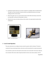
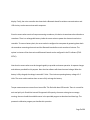
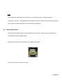
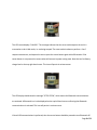
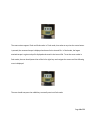
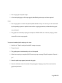
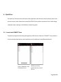
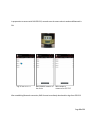
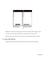
Android RAD-Connect User Manual _______________________________________________________________________________________________ Android Data Logger RAD-Connect User Manual New World Technologies Inc. 30580 Progressive Way Abbotsford, BC V2T 6Z2 Canada [email protected] Tel: 604.852.0405 www.radtorque.com Fax: 604.852.0269 E-mail: Contents 1 Introduction............................................................................................................................................................ 5 2 Smart Socket Operation ......................................................................................................................................... 6 2.1 Smart Socket Menus........................................................................................................................................ 8 2.2 Smart Socket Uptime Modes......................................................................................................................... 11 2.3 Smart Socket Internal Log File ....................................................................................................................... 12 3 Android Application Installation ........................................................................................................................... 13 4 Connecting to Devices .......................................................................................................................................... 15 5 RAD Connect Views .............................................................................................................................................. 16 6 7 5.1 CONNECT View Operation............................................................................................................................. 16 5.2 TOOL INFO View Operation ........................................................................................................................... 17 5.3 PEAK TORQUE View Operation ..................................................................................................................... 18 5.4 STORED LOGS View Operation ...................................................................................................................... 18 5.5 TORQUE GRAPHS View Operation ................................................................................................................ 19 Quick Tour ............................................................................................................................................................ 21 6.1 Launch into CONNECT View .......................................................................................................................... 21 6.2 Swipe to TOOL INFO View ............................................................................................................................. 23 6.3 Swipe to PEAK TORQUE View ........................................................................................................................ 24 6.4 Swipe to STORED LOGS View......................................................................................................................... 25 6.5 Swipe to TORQUE GRAPHS View ................................................................................................................... 27 RAD Connect Menus ............................................................................................................................................ 28 7.1 Common Menus ............................................................................................................................................ 29 7.1.1 Connection to Device Status .................................................................................................................. 29 7.1.2 Reconnect to Device .............................................................................................................................. 30 7.1.3 About ..................................................................................................................................................... 31 7.1.4 Quit ........................................................................................................................................................ 32 7.2 CONNECT View Menus .................................................................................................................................. 32 7.2.1 Scan Devices .......................................................................................................................................... 33 Page 2 of 52 7.2.2 Cancel Scan ............................................................................................................................................ 33 7.2.3 Disconnect Device.................................................................................................................................. 33 7.3 TOOL INFO View Menus ................................................................................................................................ 33 7.3.1 7.3.1.1 Tool Mode Preferences .................................................................................................................. 34 7.3.1.2 Tool Units Preferences ................................................................................................................... 34 7.3.1.3 Tool Setpoints Preferences ............................................................................................................ 34 7.3.1.4 Tool Date-Time Preferences........................................................................................................... 34 7.3.1.5 Tool Uptime Preferences ............................................................................................................... 34 7.3.1.6 Tool Security Preferences............................................................................................................... 34 7.3.2 7.4 Tool Preferences (in Six Menus) ............................................................................................................ 34 Retrieve Tool Settings ............................................................................................................................ 35 PEAK TORQUE View Menus........................................................................................................................... 36 7.4.1 Refresh Live Log ..................................................................................................................................... 36 7.4.2 Log Record Format................................................................................................................................. 36 7.5 STORED LOGS View Menus ........................................................................................................................... 37 7.5.1 Log File Description ................................................................................................................................ 38 7.5.2 Close Log ................................................................................................................................................ 38 7.5.3 Export Logs to RT Data Logger ............................................................................................................... 39 7.5.4 Export Logs as csv file............................................................................................................................. 40 7.5.5 Refresh Live Log ..................................................................................................................................... 41 7.5.6 Show Live Log......................................................................................................................................... 41 7.5.7 Log Record Format................................................................................................................................. 41 7.6 TORQUE GRAPHS View Menus...................................................................................................................... 42 7.6.1 Enable Torque Graph ............................................................................................................................. 43 7.6.2 Disable Torque Graph ............................................................................................................................ 43 7.6.3 Get Graph Mode .................................................................................................................................... 43 7.6.4 Clear Graphs .......................................................................................................................................... 43 8 Recovering Bluetooth Connection after Device Sleep.......................................................................................... 43 9 Troubleshooting ................................................................................................................................................... 46 9.1.1 TORQUE GRAPHS Not Plotting............................................................................................................... 47 Page 3 of 52 9.1.2 STORED LOGS/PEAK TORQUE Display Wrong Logs ............................................................................... 48 9.1.3 PEAK TORQUE Not Updating ................................................................................................................. 49 9.1.4 TOOL INFO Not Updating after Preferences are Set .............................................................................. 50 9.1.5 RAD Connect Displays Connection Failed while Device is Awake.......................................................... 51 Page 4 of 52 1 Introduction New World Technologies Inc. is a leading Canadian manufacturer of pneumatic, battery powered, and electronic pistol grip torque wrenches. These torque wrenches are used to tighten bolts to a specific set torque. Accessories to these torque wrenches can also be bought, one of which is the Smart Socket. The Smart Socket is a battery powered, strain gauged socket used for precision torque monitoring of fastening operations. Figure 1 shows a picture of the Smart Socket. The Smart Socket can be used with any tool and can display the torque with a +/-1% accuracy. Figure 2 show the Smart Socket in use. The Smart Socket can also display a pass or fail reading. If the torque wrench does not reach the required torque set by the user, a fail reading will be displayed on the Smart Socket screen. If the required torque is reached, a pass reading will be displayed on the Smart Socket screen. This is very helpful to the user because this allows them to know which bolts are tightened to the required standard. Another useful feature of the Smart Socket is its ability to connect to a device with a Bluetooth connection. An Android application was created to use this Bluetooth connection. This application is called RAD Torque Data Logger (RT Logger) and is available on the Google Play Store, and can be downloaded to a tablet or smartphone. Using this application, the user can interact with the Smart Socket, and perform these functions: Obtain the “Live” peak torque. By “Live”, we mean that the smart socket will be continuously monitored for new peak torque value. Page 5 of 52 Download the log file inside the smart socket and upload it to a database within the Android device. This log file can contain hundreds of records, and each record holds information such as torque readings, pass/fail, and time stamps. Observe live graphs. By “Live”, we mean that the smart socket will be continuously monitored for new torque pulls, and the pull will be plotted in real time. Read and write many smart socket settings, such as modes, units, target setpoints, uptime values, and date/time. Figure 1: The Smart Socket Figure 2: The Smart Socket In Use 2 Smart Socket Operation This section describes how to configure the smart socket for operation with this software. This device is comprised of torque measuring transducers, electronics to poll the transducers for torque measurements, micro-controller to process the measurements and save them into an internal file. The firmware inside the micro-controller offers various modes of operation offered in various menus that are shown in the LCD Page 6 of 52 display. Finally, the micro-controller also hosts both a Bluetooth board for wireless communications and USB circuitry to also communicate with computers. Since the smart socket consist of torque measuring transducers, this device is sometimes also referred as a transducer. There is a rechargeable battery inside the smart socket to power the electronics and microcontroller. To save on battery drain, the smart socket is configured to save power by powering down both the transducer measuring electronics and the Bluetooth board after certain number of minutes. The uptime in minutes of the electronics and Bluetooth boards can be configured in the PC software (TOOL SETUP). Note that the smart socket must be charged regularly to provide continuous operation. A separate charger and cable are provided for this purpose. Note that the software will show the actual voltage. When the battery is fully charged, the voltage is around 4.2 Volts. The minimum operating battery voltage is 3.6 Volts. The smart socket needs an hour or two to fully recharge the battery. Torque measurements are stored in an internal file. This file holds about 350 records. There is a record for each tool pull cycle. Should the internal file approach full capacity, the smart socket gives a message warning; the user should the available menus in the provided program to download and close logs. The pneumatic calibration program part handles this operation. Page 7 of 52 Note: In the manual the smart socket is also referred to in several ways: “device”, “Bluetooth device”, “transducer”, and “tool”. These designations came about since there are other variants of the smart socket, such as Torque Transducer and RAD TV Tools with built-in transducers. 2.1 Smart Socket Menus The smart socket exhibits various menus displayed in the LCD screen. These menus are actuated by the center button, and the left/right buttons. When the smart socket is first handled, the LCD display will be blank: Press the center button to wake the socket: Page 8 of 52 The LCD screen displays “UNLOAD”. The message indicates that the smart socket expects the tool it is mounted on to be in idle mode, i.e. not being torqued. The smart socket is about to perform a “zero” torque measurement, and expects the user to press the center button again within 60 seconds. If the center button is not pressed, the smart socket will resume its power saving state. Note the icon for Battery charge level on the top right hand corner. This icon will persist in various menus. The LCD display should show the message “SETUP BT ON”, which means the Bluetooth communications are activated. A Bluetooth icon is also displayed on the top left hand corner confirming that Bluetooth communications is activated. This icon will persist in various menus. If wired USB communications is preferred, then the center button should be pressed to turn Bluetooth off: Page 9 of 52 The smart socket supports Track and Peak modes. In Track mode, then when at any time the center button is pressed, the measured torque is displayed and stored in the internal file. In Peak mode, the largest attained torque in a given tool pull is displayed and stored in the internal file. To set the smart socket in Peak mode, the user should press either of the left or right keys and navigate the menus until the following menu is displayed: The user should now press the middle key to actually enter into Peak mode: Page 10 of 52 When the tool is torqued in a pull cycle, the highest torque value is displayed: Note: To get back from torque display in Peak Mode and back into other menus, the user must press the center button continuously for at least 5 seconds. Afterwards, the LCD display will display the Setup menus and one can navigate with the right or left buttons. This 5 second press and hold procedure also applies when the smart socket is in Track mode and displaying a torque value. 2.2 Smart Socket Uptime Modes The smart socket is powered by a battery which powers the socket electronics and Bluetooth boards. It is not practical to leave the various electronics powered up indefinitely since this will quickly drain the available charge. Page 11 of 52 It is important to discuss the two uptime modes in a smart socket: 1. Socket Uptime. The socket powers the transducers, LCD display, and motherboard electronics. The uptime period, in minutes, is the length of time that the socket will remain active and after which the display blanks. The socket can be re-powered by pressing the center button in the smart socket. 2. Bluetooth Uptime. The Bluetooth board is also powered by the battery. The uptime period, in minutes, is the length of time that the Bluetooth board remains active and after which Bluetooth is powered off, and the Bluetooth symbol disappears from the LCD display. Note that when the socket uptime period expires the Bluetooth board will also go to sleep. The Bluetooth can be reactivated by pressing the appropriate menu from the LCD display. RAD Connect can manage the socket and Bluetooth uptimes through the preference menus in the TOOL INFO view. The application has menu functions to detect sleep conditions and recovery to connect back to the smart socket. 2.3 Smart Socket Internal Log File The smart socket has a single and permanent internal file. This file is filled with records where each record contains information of a single torque pull: Record ID or Bolt number Date of torque pull, in year/month/day format Time of torque pull, in hour: minute AM/PM format Page 12 of 52 Actual torque Units of torque Pass/Fail (if target mode is set) Torque pull duration The capacity of the file varies depending on the smart socket model. Typically 300 to 400 records maximum capacities. When the number of records is about to be exceeded, the LCD displays a warning “Logs Nearly Full”, and with any more torque pulls the message changes to “Logs are Full”. Some smart socket models may not register any more records, and others may not operate until the log file is erased. This is performed by RAD Connect in the STORED LOGS view via the Close Log menu. 3 Android Application Installation The RAD Connect application can be downloaded from the Google Play Store. The application has been inhouse tested in the following android versions: Version 4.1 to 4.3, also known as “Jelly Bean”, API levels 16, 17, 18 Version 4.4, also known as “KitKat”, API level 19 Version 5.0.2, also known as “Lollipop”, API level 21 Furthermore, the application has been tested in phones/tablets with th efollowing screen sizes: 4.3” (Nexus 4) 7.0” (Samsung Tab 3) Page 13 of 52 10.0” (Samsung Tab 3) Notes: RAD Connect may not operate with earlier such as android version 3.0 (Honeycomb) and even earlier. RAD Connect supports both portrait and landscape rotations. The figures in this manual are obtained with a Samsung 7” tablet with Android version 4.2.2 (KitKat) It is useful to determine the version of your Android: Tap into the tablet/phone Settings Locate Android version as shown. Page 14 of 52 4 Connecting to Devices This Section outlines steps to connect to smart sockets via the Android Bluetooth settings. The following figures below outline discovery and pairing of the Smart Socket, serial number RAD SS31313: Tap on the Settings symbol. Tap Bluetooth panel, then tap on Scan Tap on the discovered device, RAD SS31313 Enter the pin. It is factory set to 1111 or 1234. Note that RAD SS31313 is moved up to Paired devices To unpair, or pair with new pin, tap on the setting symbol. Page 15 of 52 5 RAD Connect Views This application has five views. All views share a consistent user interface comprising of the header (top) part, view selector ribbon (tabs), main body (page), and footer (bottom): Header part consists of the program title, connection to device status symbol, reconnect to device symbol, and menu access symbol View selector ribbon displaying tab or view names. Currently there are five tabs. Tapping on the individual tab invokes the view page Main body. This is the page view and shows the main pertinent information and data Footer part consists of a ‘live’ status bar. This bar has the following format: {Serial Number}> {status message}. The status messages display the information exchange communication link between RAD Connect and the smart socket, where the RAD Connect sends commands to the device, and the smart socket replies with requested status and data. We next discuss the tab views and how to operate them. 5.1 CONNECT View Operation This view is used to: 1. Scan nearby smart socket devices, 2. Pair with new smart socket devices, Page 16 of 52 3. Show previously paired Bluetooth devices, 4. Connect with Bluetooth devices 5. Re-connect with Bluetooth devices To operate with this view: 1. Tap the smart socket serial number appearing in the list of paired devices, 2. Wait for the “Connected” message to pop-up, followed by “RAD Data Logger is ready to use”. 3. Swipe to any other view If the smart socket serial number does not appear in the list, tap on MenusScan Devices. 5.2 TOOL INFO View Operation This view is used to: 1. Display/review all the smart socket settings. 2. Adjust any of the following settings Mode, Units, Setpoints, Date-Time, Uptime and Security via six menu preferences. To operate immediately after swiping to this view: 1. Wait few seconds until all the Tool Settings fields fill up with values. 2. Scroll down the settings to inspect values 3. If any value needs to be changed, tap MenusTool … Preferences Page 17 of 52 5.3 PEAK TORQUE View Operation This view is polls the smart socket every few seconds for new peak torque. The display consists of: 1. Last peak torque and time 2. A list view displaying the current log in the smart socket To operate immediately after swiping to this view: 1. Torque the tool 2. The message “Processing new log data” will flash within 2 seconds 3. New Peak Torque appears 5.4 STORED LOGS View Operation This view displays the log files stored in the database within the Android phone/tablet. The display consists of: 1. Drop-down list of smart socket serial numbers 2. Drop-down list of log files corresponding to the selected smart socket serial number 3. A list view displaying the records of the selected log file The following functions are available via the menus: 1. Log files can be exported into the PC based RT Data Logger, 2. Log files can be exported as comma separated text files with .csv extensions, 3. Current log in the smart socket can be closed Page 18 of 52 To operate immediately after swiping to this view: 1. Observe the Tool SN which starts with “LIVE …”, and followed by the serial number of the connected smart socket 2. Observe the Log Title. This log is inside the Android’s database. It matches the actual log file inside the smart socket too. 3. Observe Log Status. If says “Log Open”, then this is the “Live” log. This file can be appended by torqueing the tool. 4. Note: This is not a live page. If the tool is torqued in this view the live log will not update. One can update the live log in two ways: (1) by tapping MenusRefresh Live Log, or (2) by swiping out of this page and immediately swipe back in. 5. Press the serial number of Tool SN: This pops up a drop down box showing the list of devices already stored in your tablet/phone. 6. Press the log title name: This pops up a drop down box showing the list of log files for this device already stored in your tablet/phone. When you select one of the titles, the log data fills the list page just below. 5.5 TORQUE GRAPHS View Operation This view displays the “live” torque graph. The display consists of: Page 19 of 52 1. The torque graph and peak torque. 2. A list view displaying up to 20 torque graphs, identified by peak torque and time acquired. Notes: 1. The torque graphs are saved in the phone/tablet volatile memory. The memory can be “reclaimed” by the operating system as required to serve other on-going operations, and therefore the graphs may be cleared. 2. The graphs are retained by swiping to the adjacent STORED LOGS view. However, swiping to other views will clear the torque graphs. To operate immediately after swiping to this view: 1. Wait for the “Graph is ready and enabled” message to pop-up. 2. Torque the tool. 3. The graph appears simultaneously as the tool is torqued. 4. When the torqueing is completed, RAD Connect pops up a message “Graph Completed. Captured … pts.” 5. Note the peak torque appears just under the graph 6. Note the list below shows the number of torqued graphs. Tapping in any of them retrieves the graph and peak value. Page 20 of 52 6 Quick Tour This quick tour illustrates the several facets of the application. We will connect with the device paired in the previous section, Smart Socket serial number RAD SS31313, then perform operations such as read settings, read peak torque, read logs in the database, and plot live graphs. 6.1 Launch into CONNECT View The quick tour begins with launching the application, RAD Connect, shows the “CONNECT” view, presents a list of previously paired devices, and immediately scans for additional nearby Bluetooth devices. RAD Connect launches with an immediate scan of nearby devices The list of devices include previously paired and newly found devices Page 21 of 52 In preparation to connect with RAD SS31313, we make sure the smart socket is awake and Bluetooth in ON. Tap on the SS31313 RAD Connect connects to the device RAD Connect is connected to SS31313 After establishing Bluetooth connection, RAD Connect immediately downloads the logs from SS31313: Page 22 of 52 RAD Connect starts downloading logs… All logs are downloaded. RAD Connect is ready for use. Note: The user is advised to start swiping to other views after the message “RAD Data Logger is ready to use” pops-up, or when “All logs are downloaded…” message shows in the bottom status bar. TIP: One can select a paired device to connect while a scan for nearby Bluetooth devices is on-going. 6.2 Swipe to TOOL INFO View Swiping to the next view, TOOL INFO, RAD Connect polls the smart socket for the entire settings: Page 23 of 52 This view offers the user the current settings in the smart socket and allows him to alter them in several preference menus (Please refer to the RAD Connect Menus Section). Note: The battery voltage offers a glimpse of the available charge. The battery voltage ranges from a low of 3.6 V to a maximum of 4.2 V. When the battery loses charge towards the low value the user is advised to give the smart socket a quick one hour charge. 6.3 Swipe to PEAK TORQUE View Swiping to the next view, PEAK TORQUE view, the RAD Connect polls the smart socket every few seconds for the most recent peak torque value. Page 24 of 52 The view presents a list of all the logs in the smart socket, and displays the most recent torque and the time it was acquired. When a new peak torque is detected, it pops-up a quick message “Updating Torque Logs…” Note that with this view, the constant polling of the smart socket prevents the device from going to sleep. Caution should be applied to make sure there is ample voltage in the device (TOOL INFO Battery). 6.4 Swipe to STORED LOGS View Swiping to the next view, STORED LOGS view, the RAD Connect displays the current log in the smart socket, as well as log files stored inside Android’s SQLite database. Page 25 of 52 This view displays the following: Tool Serial Number. RAD Connect can connect to more than one smart socket, and the log files for each tool are separated by the tool serial number. This field is a drop down box. Tapping on the serial number will display a list of serial numbers saved in the database. The “Live” name prefix indicates the currently connected device. Log Title. RAD Connect assigns the title internally based on date and time the log was first acquired. This field is a drop down box. Tapping on the log file title name will display a list of log files corresponding to the serial number saved in the database. Log Description. The description of the log can be assigned via the menu system. Log Status. Either Open or Closed. Open means this log is presently being filled by the smart socket internal file. Once the user decides to close the log via the menu system, RAD Connect erases the file within the smart socket and designates the saved log file in the database as closed. Page 26 of 52 Log records. 6.5 Swipe to TORQUE GRAPHS View Swiping to the next view, TORQUE GRAPHS view, the RAD Connect displays the “live” torque graph. When this view is first swiped, RAD Connect enables graph mode in the smart socket, and thus requires few seconds. The following messages will be displayed: RAD Connect sends graph RAD Connect polls the enable to smart socket smart socket to confirm setting RAD Connect shows success. Graphing is ready. Note: The user is advised to wait after the message “Graphing is enabled and ready” pops-up, and then to start torqueing the tool. When the user pulls the torque, graphing will commence: Page 27 of 52 The display shows the graph, and at completion of the pull displays completion and number of captured points. The list below has the number of graphs pulled already. Tapping on any one of them will display the appropriate graph. Note that 20 graphs can be stored, but this is determined by the amount of memory in the phone/tablet. 7 RAD Connect Menus Each view of RAD Connect has its own menus. These menus are categorized as: Commands for executing specific functions, Utility for reporting back various states, and Information for displaying settings Page 28 of 52 7.1 Common Menus While each view has its own menus, there are menus common to each View. These will be discussed here. 7.1.1 Connection to Device Status This menu is a utility. It checks the current Bluetooth connectivity state. There are three possible states: 1. Connected State. Bluetooth was previously connected from the CONNECT view. In this case, the program will re-connect with the device. If the device could re-connect again, it popes-up a message that the device is connected. Otherwise, it pops-up a message that connection failed. 2. Connection Failed State. Bluetooth connectivity was lost after the smart socket’s uptime (Bluetooth or socket) expired. The program will pop-up a message that the connection failed. 3. Disconnected State. There was no previous Bluetooth connection since the program started, in this case the program pops-up a message that a device must be connected. Note: This menu is also accessible via a shortcut in the action bar (header view) as shown in the figure below: Page 29 of 52 7.1.2 Reconnect to Device In the event the device goes to sleep, the Bluetooth connection will be lost. The user should set the device awake, turn on Bluetooth in the LCD panel, and then select this menu command. In this case, the program will re-connect with the device. If the device could re-connect again, it popes-up a message that the device is connected. Otherwise, it pops-up a message that connection failed. If this menu fails to re-connect to the smart socket, it is best to swipe to the CONNECT view and re-select the same device. Note: This menu is also accessible via a shortcut in the action bar (header view) as shown in the figure below: Page 30 of 52 7.1.3 About This menu command pops-up an about information dialog with version of this application and build history. Page 31 of 52 7.1.4 Quit Presents a confirmation dialog to close RAD Connect. 7.2 CONNECT View Menus These are the menus in this view: Page 32 of 52 7.2.1 Scan Devices This menu is a command to start scanning new Bluetooth devices. 7.2.2 Cancel Scan This menu is a command to cancel an on-going Bluetooth scan of nearby devices. 7.2.3 Disconnect Device This menu is a command to disconnect an already connected smart socket. This command is useful when having multiple smart sockets; one should disconnect a device before connecting to another. 7.3 TOOL INFO View Menus Page 33 of 52 These are the menus in this view: 7.3.1 Tool Preferences (in Six Menus) The following six tool preference menus present settings that can be modified as shown in the figures that follow. 7.3.1.1 Tool Mode Preferences 7.3.1.2 Tool Units Preferences 7.3.1.3 Tool Setpoints Preferences 7.3.1.4 Tool Date-Time Preferences 7.3.1.5 Tool Uptime Preferences 7.3.1.6 Tool Security Preferences Page 34 of 52 Mode Preferences Units Preferences Setpoints Preferences Date-Time Preferences Uptime Preferences Security Preferences 7.3.2 Retrieve Tool Settings This menu is a command where the RAD Connect polls the smart socket for the entire settings. Page 35 of 52 7.4 PEAK TORQUE View Menus These are the menus in this view: 7.4.1 Refresh Live Log This menu is a command to force the RAD Connect to get the updated peak torque value. This is normally not needed since the device is polled every few seconds anyway. However, in the event that the phone/tablet has lost connectivity for a while while the tool is torqued, using this menu will recover to the list view the missing peak torques. 7.4.2 Log Record Format This menu is a command to display the description of the records in the log. Page 36 of 52 7.5 STORED LOGS View Menus These are the menus in this view: Page 37 of 52 7.5.1 Log File Description This menu launches an input box to allow the user to enter a description for the selected log file. 7.5.2 Close Log This menu launches a confirmation dialog box which if accepted performs these steps: 1. Erases the current log file in the smart socket 2. Saves the log file in the database with the “closed” designation. This designation implies that the log file in the database cannot be appended with any more records. Page 38 of 52 Note that when the log is closed, the log status display will show “Closed on {time} {date}”. The log records are maintained in the view. When new torques are pulled, the user needs to see the new open log by: 1. Tap on MenuRefresh Live Log 2. Tap on MenuShow Live Log 7.5.3 Export Logs to RT Data Logger This menu launches a multiple selection dialog box to specify what logs to export to the PC based RT Data Logger: Current log. This exports the currently selected log title. All of selected tool SN logs. As the name implies. All logs. All the stored logs are exported Page 39 of 52 Export options Export file attachment via mail options Send attachment to email recipient 7.5.4 Export Logs as csv file This menu launches a multiple selection dialog box to specify what logs to export to the PC based RT Data Logger: Current log. This exports the currently selected log title. All of selected tool SN logs. As the name implies. All logs. All the stored logs are exported Page 40 of 52 Export options Export file attachment via mail options Send attachment to email recipient 7.5.5 Refresh Live Log This menu function communicates with the smart socket to import the latest log records. RAD Connect stores the newest logs. 7.5.6 Show Live Log This menu function will display the open log of the connected live tool. This is simply a shortcut to spare the user from tapping the Tool SN and Log Title. 7.5.7 Log Record Format This menu is a command to display the description of the records in the log. Page 41 of 52 7.6 TORQUE GRAPHS View Menus These are the menus in this view: Page 42 of 52 7.6.1 Enable Torque Graph This menu is a command to force enable graph mode in the smart socket. Normally this command is not required since RAD Connect automatically enables graph mode when this view is swiped. This menu is included for diagnostics and troubleshooting. If the graph mode does not activate automatically when entering this view, it is useful to tap menuDisable Torque Graph, then tap menuEnable Torque Graph. 7.6.2 Disable Torque Graph This menu is a command to disable graph mode in the smart socket. This menu is included for diagnostics and troubleshooting. If the graph mode does not activate automatically when entering this view, it is useful to tap menuDisable Torque Graph, then tap menuEnable Torque Graph. 7.6.3 Get Graph Mode This menu is a command to obtain the graph mode, enabled or disabled. This menu is included for diagnostics and troubleshooting. 7.6.4 Clear Graphs This menu clears all the graph sets. 8 Recovering Bluetooth Connection after Device Sleep Assume that the Smart Socket Socket/Bluetooth uptime expires, and either the Bluetooth symbol in the LCD panel disappears or the LCD Panel goes blank. If one swipes to a new view, or activates a menu Page 43 of 52 function, then RAD Connect may flash a two seconds message or a dialog box indicating that the Connection failed. Note that RAD Connect requires finite time to detect a loss of connection, typically 7 to 10 seconds. The reason is that there the program polls the smart socket for extra time in an effort to re-connect and reestablish Bluetooth connection. It is useful to test the connection by tapping menuConnection to Device Status which is available in all views. This pops-up an alert box that must be tapped to disappear. Page 44 of 52 The first course of action is to re-activate the smart socket from sleep. In the case of smart socket sleep (LCD display is blank), press the middle button twice. The first selection will cause the display to turn on and displays “unload”. This message is a reminder to the user not to pull torque yet; the smart socket is internally recalling “calibration of zero” condition. Pressing the middle button again will show setup messages such as “Setup BT…” and “Setup Peak”. Check the Bluetooth sleep according to the next step. In the case of Bluetooth sleep, navigate the left and right buttons in the smart socket to reach “Setup BT Off” or “Setup BT On”, where BT stands for Bluetooth. In the case of the former message, then press the center button until the display switches Bluetooth on. The Bluetooth symbol will display on the top left. We now can take one of possible two actions to re-connect RAD Connect to the smart socket, as displayed in the RAD Connect message: Page 45 of 52 1. Tap on the menuReconnect to device, or, 2. Swipe back to CONNECT view, and re-select the device from the list. This method can be more reliable since additional Bluetooth checks are undertaken in this view. Finally, if these steps do not result in a Bluetooth connection between the smart socket and RAD Connect, it is worthwhile to do these checks: 1. Confirm Bluetooth pin pairing by using Android SettingsBluetooth to scan and confirm pairing. Sometimes it helps to un-pair the smart socket and re-pair again. 2. Hard reset the smart socket (with a pin), and re-activate Bluetooth (SETUP BT ON). 3. Connect with the RAD Connect. 9 Troubleshooting In most cases RAD Connect runs reliably to connect with a smart socket, retrieve data and display information. This is achieved by an information exchange communications link where the RAD Connect sends commands to the device, and the smart socket replies with requested status and data. This link is continuous in the case of PEAK TORQUE and TORQUE GRAPHS views. The other views utilize this link only when the user interacts with the program. There are some cases where the information exchange link between the application and the device may get interrupted by the tool going to sleep, or for other reasons. This section outlines steps to recover the information exchange communications link. Page 46 of 52 9.1.1 TORQUE GRAPHS Not Plotting Condition: The smart socket is awake and linked, and, TORQUE GRAPHS view pops up the message “Graphing is enabled and ready”, and, TORQUE GRAPHS do not plot. The following solutions should be tried in the same order. Solution #1: Tap menuDisable Torque Graph Tap menuEnable Torque Graph Solution #2: Swipe to CONNECT view Tap on the device name in the list of paired devices. Swipe back to TORQUE GRAPHS Solution #3: Hard reset the smart socket (with a pin), and re-activate Bluetooth (SETUP BT ON). Swipe to CONNECT view Page 47 of 52 Tap on the device name in the list of paired devices. Swipe back to TORQUE GRAPHS 9.1.2 STORED LOGS/PEAK TORQUE Display Wrong Logs This may arise when one connects to multiple smart sockets. If one taps a new smart socket in the CONNECT view the logs from the previous smart socket may persist in either STORED LOGS or PEAK TORQUE views. Condition: Tool SN: displays the proper connected smart socket serial number Log Title: displays logs belonging to another Tool SN. Solution: Swipe to CONNECT view Tap on menuDisconnect Device Tap on the device name in the list of paired devices. Swipe back to STORED LOGS or PEAK TORQUE view Page 48 of 52 9.1.3 PEAK TORQUE Not Updating Condition: The smart socket is awake and linked, and, User torques the tool. PEAK TORQUE view does not pop up the message “Updating Torque Logs…” 5 seconds after the tool finishes torqueing The following solutions should be tried in the same order. Solution #1: Swipe to CONNECT view Tap on the device name in the list of paired devices. Swipe back to PEAK TORQUE Solution #2: Navigate the Smart Socket LCD menu to “Setup Peak” Note: If the Smart Socket cannot navigate screens, then follow the steps of the next solution. Swipe to CONNECT view Tap on the device name in the list of paired devices. Swipe back to PEAK TORQUE Page 49 of 52 Solution #3: Hard reset the smart socket (with a pin), and re-activate Bluetooth (SETUP BT ON). Swipe to CONNECT view Tap on the device name in the list of paired devices. Swipe back to PEAK TORQUE 9.1.4 TOOL INFO Not Updating after Preferences are Set Condition: User adjusts smart socket settings using menu-> … Preferences User Saves the Preference dialog box. Tool Settings do not retrieve some or all the fields Solution: Swipe to CONNECT view Tap on the device name in the list of paired devices. Swipe back to TOOL INFO Page 50 of 52 9.1.5 RAD Connect Displays Connection Failed while Device is Awake RAD Connect may lose connectivity with the smart socket due to electrical interference or to loss of line of sight or increasing distance between the phone/tablet and the device. Yet there are cases where connectivity is lost when tool preferences are written to the device; settings are written into the flash memory and may require re-booting the device. The specific case in point here has these symptoms: Condition: All view pages may flash or pop-up “Connection Failed..” message Smart Socket is Awake. The following solutions should be tried in the same order. Solution #1: In the same view, tap MenusConnection to Device Status to confirm the device connection condition In the same view, tap MenusReconnect to Device Solution #2: Swipe to CONNECT view Page 51 of 52 Tap on the device name in the list of paired devices. Solution #3: Navigate the Smart Socket LCD menu to “Setup BT ON” Turn BT OFF, then back ON Swipe to CONNECT view Tap on the device name in the list of paired devices. Solution #4: Hard reset the smart socket (with a pin), and re-activate Bluetooth (SETUP BT ON). Swipe to CONNECT view Tap on the device name in the list of paired devices. Page 52 of 52