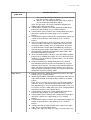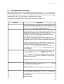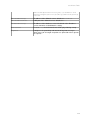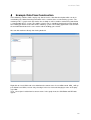
1
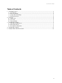
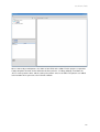
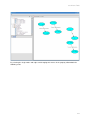
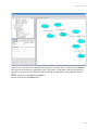
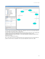
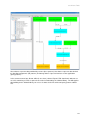
trackframe Tools trackframe Tools: trackman Version: 1.00.00 Date: December 21, 2008 Funded by Authors: Peter Keitler Project partners: 1 trackframe Tools Table of Contents 1 Installation Process............................................................................................................................3 1.1 Prerequisites................................................................................................................................3 1.2 Basic Installation..........................................................................................................................3 1.3 Setup Ubitrack Bindings..............................................................................................................3 1.4 Running trackman........................................................................................................................4 2 Overview............................................................................................................................................5 2.1 Graph view...................................................................................................................................5 2.2 Tree view.....................................................................................................................................5 2.3 Property Editor.............................................................................................................................5 3 Functionality in Detail.........................................................................................................................7 3.1 SRG Construction Basics............................................................................................................7 3.2 Data Flow Analysis......................................................................................................................7 3.3 Description of Operations............................................................................................................8 4 Configuration Settings.....................................................................................................................13 5 Example Data Flow Construction.....................................................................................................15 2 trackframe Tools 1 Installation Process trackman has been developed fully in Java for the sake of platformindependency. This facilitates the use of trackman not only as an offline planning tool but also as an online data flow analysis tool in combination with the open source Ubitrack library. This combination of Ubitrack and trackman should run at least on Linux, MS Windows XP, MS Windows Vista and Mac OS X platforms. 1.1 Prerequisites At least the following prerequisites have to be fulfilled in order to run trackman: ● A Java SE Runtime Environment (JRE or JDK) version 6.0 or higher has to be installed on your machine. It can be downloaded from http://java.com/en/download/manual.jsp. ● A trackman binary package trackman_<version>.zip version 1.00.00 or higher. In order to make use of the online data flow analysis functionality of trackman, additionally the follow ing software has to be installed in advance: ● Java3D version 1.5.1 or higher has to be installed into your JRE directory. It can be down loaded from https://java3d.dev.java.net/binarybuilds.html. ● A current installation of the Ubitrack tracking library is needed. It can be obtained from http://campar.in.tum.de/UbiTrack/WebHome. 1.2 Basic Installation In order to install trackman on your computer, just unzip the trackman installation package in a direc tory of your choice. In case of updating from a previous version, you might want to copy the track man.conf file from your old installation directory in order to keep your current settings. By default, trackman reads in the various pattern templates supported by the Ubitrack library from the pattern template directory hierarchy at startup. They are located in the bin/ subdirectory of your trackman installation directory. See chapter 4 for information about how to keep in sync with progress in Ubitrack development. Installation is finished if you do not need the online data flow analysis func tionality. 1.3 Setup Ubitrack Bindings This section can be skipped if the online data flow analysis functionality of trackman is not needed. To instantiate Ubitrack data flows, trackman has to know about which Ubitrack installation to use. This is accomplished by three configuration settings in your trackman.conf file contained in the bin/ sub directory of your trackman installation. ● UbitrackComponentDirectory has to point to the directory containing all ubitrack data flow components, probably a subdirectory of lib/ or bin/ in your ubitrack installation. Windows example: UbitrackComponentsDirectory=C\:\\Dokumente und Einstel lungen\\keitler\\Desktop\\ubitrack\\bin\\ubitrack ● UbitrackWrapperDirectory has to point to the directory containing the ubitrack.jar file. Windows example: UbitrackWrapperDirectory=C\:\\Dokumente und Einstellun gen\\keitler\\Desktop\\ubitrack\\lib ● UbitrackLibraryDirectory has to point to the directory which contains the libubi track.so (Unix) / ubitrack.dll (Windows) native library, probably either lib/ or bin/. Windows example: UbitrackLibraryDirectory=C\:\\Dokumente und Einstellun gen\\keitler\\Desktop\\ubitrack\\bin An exemplary configuration file is included in the trackman installation package trackman_<ver sion>.zip. See also chapter 4 for further information about these settings. Note that “\” characters in Windows paths have to be quoted by a preceding, second “\” in trackman.conf. 3 trackframe Tools Furthermore, the dynamic linker of your operating system has to be configured to load dynamic li braries (*.so, *.dll, ...) from this location, too. Depending on your platform, this is accomplished in different ways: ● Linux: Either add the lib/ subdirectory of your Ubitrack installation to the LD_LIBRARY_PATH environment variable or add this directory to your /etc/ld.so.conf and run ldconfig as root. ● MS Windows XP / Vista: Add the lib/ subdirectory of your Ubitrack installation to the PATH environment variable. ● Mac OS X: Add the lib/ subdirectory of your Ubitrack installation to the DYLD_LIBRARY_PATH environment variable. If the UbitrackLibraryDirectory property is unset, trackman will disable automatically all online data flow functionality and configuration of your dynamic linker is not necessary. See also chapter 4 for further information about this configuration property. 1.4 Running trackman trackman is started by changing to the bin/ subdirectory of your installation and typing java jar trackman_<version>.jar in the console. Under MS Windows you should be able to start it by doubleclicking on the jarfile if the JRE has been installed correctly, though console output is sometimes useful, especially when using Ubitrack for data flow instantiation. 4 trackframe Tools 2 Overview The main view consists of a hierarchical tree view on the upper left hand side, the property editor on the lower left hand side and the main graph view on the right hand side, as can be seen in Figure 1. Figure 1: trackman main view 2.1 Graph view The graph view is currently showing the the SRG Editor tab which is used for editing SRGs. The „DFN“ tab (data flow network) which is currently inactive, is a pure visualization of the data flow result ing from the current SRG layout, as will be seen later. 2.2 Tree view The tree view is always showing three root elements: ● The database server node contains projects available on the Ubitrack database server. Each project has a unique ID by which it is represented in the tree and and contains SRGs belong ing to this project. The SRGs in turn are also represented by their ID and contain the SRG pat tern instances they consist of. ● The local SRGs node behaves very similar to the projects contained by the database server. It is a pool for SRGs imported from files. ● The pattern templates node contains pattern templates that can be instantiated in your SRG via drag and drop. 2.3 Property Editor trackman always always keeps track of selection of objects in the tree view and graph view. It is possi ble to select an element or an object by a single leftclick. If one object is selected, its properties are 5 trackframe Tools shown in the property editor on the bottom left, along with a brief description. The properties shown in grey are readonly and the properties shown in black can be edited. It is also possible to select several objects simultaneously by holding the CTRL key down during the leftclick This will be needed by some of the graph editing actions later on. If several objects are se lected, the property editor will be deactivated. 6 trackframe Tools 3 Functionality in Detail 3.1 SRG Construction Basics Pattern templates from the query patterns, full patterns and base patterns nodes in the tree view can be added to the SRG currently shown in the SRG editor via a drag and drop operation. Once several patterns have been added, they can be combined to construct the SRG. Mainly two input metaphors are used for combining patterns. ● ● Node unification is used to combine at least two nodes belonging to the output sections of dif ferent patterns. In the SRG view, all participating nodes are replaced by a single newly intro duced node called supernode. All attributes of the unified nodes are aggregated at the supern ode and can henceforth be edited in the property editor by selecting the supernode. If two or more unified nodes share the same attribute, it can henceforth be edited consistently for all of them. In UTQL requests, the supernode pattern is added to represent the supernode which serves as container for attributes used by the unified nodes in order to avoid redundancy. For UTQL responses, the supernode is not relevant and the attributes of the unified nodes are set directly at the single nodes since during instantiation of a UTQL request, each driver or data flow component only reads in its pattern instance. The process of assigning an edge contained in the input section of one pattern with an edge contained in the output section of another pattern is called edge matching. This always implies that the source and sink nodes of the input edge are also matched against their corresponding nodes of the output edge. In UTQL requests, this matching is expressed by predicates set accordingly by trackman. in UTQL responses, this matching is expressed by setting pattern, node and edge IDs appro priately. Both metaphors for SRG construction are invoked via the context menu of the affected SRG nodes and edges, as described in the following section. For further information about the Ubiquitous Tracking Query Language (UTQL), please refer to the technical report The Ubiquitous Tracking Query Language (UTQL) Version 1.0 which can be down loaded from http://campar.in.tum.de/twiki/pub/UbiTrack/WebHome/utql.pdf. 3.2 Data Flow Analysis The data flow described by a certain SRG can be instantiated using the open source Ubitrack library by invoking the instantiate data flow operation on the SRG. Please refer to 1.2 for information about how to enable this functionality in trackman. Data Flow Comparison trackman supports relative comparison of alternative data flows against a selected reference data flow. This functionality is currently implemented only for transformations with type pose. To perform data flow comparison, register one “Application push sink (pose)” pattern (push sink) in the SRG, along with one or several “Application pull sink (pose)” patterns (pull sink). If there are more than one patterns of the former type, the first pattern instance will be used as reference. Attention: This feature only yields reasonable results if the push and all the pull sinks are situated be tween the same two nodes and all point in the same direction. Pushing Events into the Data Flow If you want to push events into the data flow, e.g. in order to make measurements in userdefined po sitions, use an “Application push source (button)” pattern as event source in your SRG. Only one in stance of this pattern is supported at the moment and the first will be used in case of doubt. 7 trackframe Tools Data Flow Instantiation As a prerequisite for data flow instantiation, all mandatory attributes of all patterns/nodes/edges in the SRG have to be set appropriately, an error message describing the problem will be generated other wise. If data flow instantiation is successful, the Data flow dialog as shown in Figure 2 will be opened. Figure 2: trackman data flow interaction and analysis The plot in the upper left shows the rotational error for each registered pull sink relative to the regis tered push sink, each pull sink having a distinct color. Analogously, the plot in the lower left shows the translational error (euclidean distance) for each registered pull sink. The plots will remain empty if no push / pull sinks have been registered, as described in above in this section. Setting the Enable axes checkbox results in plotting the relative distances in each of the three coordi nate axes in addition. The units of the coordinate axes adapt appropriately as tracking data is generated by the data flow network. Pressing the Reset axes button throws away all existing data and thus adapts scaling of the axes to the current state of the system. Pressing the Measurement button pushes an event into the data flow as described above in this sec tion. Pressing the Pause button temporarily freezes the data flow. It can be resumed by pressing the Con tinue button. Pressing Stop stops and deregisters the data flow and also closes the Data flow dialog. 3.3 Description of Operations Almost all program options are reached via the context menu of the elements shown in the tree and graph views which will be displayed upon a single rightclick on the element. For some actions, sev 8 trackframe Tools eral elements of a certain type have been selected and the semantics of the action depends on the se quence of selection. The following table lists the available options for each element and gives a description of its seman tics. Element in tree or graph view Database Server Available operations ● ● ● Database server → <ProjectName> ● ● ● ● ● ● Database server → <ProjectName> → <SRGName> ● ● ● ● ● ● ● ● ● Load from database: Loads/refreshes all projects with SRGs represented by proxy objects from database server. All current contents of the Database Server tree (projects and SRGs) will be removed first. A warning will be shown if this leads to data loss. This operation is also performed automatically on trackman startup Save in database: Persists all projects an all SRG proxy ob jects and currently open SRGs to database. Database contents having the same IDs will be updated but other database con tents will remain unchanged. New: Create a new project in memory. A unique ID will auto matically be suggested. New: Creates a new empty SRG in memory Load: Imports an SRG from a file containing a UTQL request. The ID of the SRG is either taken from the UTQL file if avail able or generated by trackman. SRGs are the default storage format used by trackman. Import data flow description: Imports a DFG from a file contain ing a UTQL response. The ID of the DFG is either taken from the UTQL file if available or generated by trackman. DFGs are needed for data flow instantiation using the Ubitrack library. Load from database: As above but for single project only Save in database: As above but for single project only Delete: Deletes the project persistently. Save: Exports this SRG to a file in the UTQL request format that can be used to register the SRG at the Ubitrack server. This is the preferred storage format. Export data flow description: Exports this DFG to a file in the UTQL response format that can be used for direct instantiation by a Ubitrack tracking client. DFGs are complete and selfcon tained SRGs. All mandatory pattern/node/edge attributes must be set and no unmatched input nodes/edges are allowd. Load from database: As above but for a single SRG only Save in database: As above but for a single SRG only Close: Closes an opened SRG removing it from trackman con text, leaving only a SRG proxy object in the tree. A warning will be shown if this leads to data loss. Export SRG as PNG: Exports an screen shot of the SRGEditor tab in PNGFormat (portable network graphic). Export DFN as PNG: Exports an screenshot of the DFN tab in PNGFormat (portable network graphic). Export SRG as SVG: Exports an screen shot of the SRGEditor tab in SVGFormat (scalable vector graphic). Instantiate data flow: Instantiates the data flow described by this SRG using the Ubitrack library. See 3.2 for further informa 9 trackframe Tools Element in tree or graph view Available operations ● ● ● tion. Delete: Removes this SRG from program context and deletes it in database. Open in editor: Shows the SRG in the graph view Register SRG: Creates a UTQL request from the SRG and reg isters it at the configured Ubitrack server. Local SRGs Same functionality as described for Database server → <ProjectID> except that the operations load from database, save in database and delete are not available Local SRGs → <SRGName> Same functionality as described for Database server → <ProjectID> → <SRGID> except that the operations load from database, save in data base and delete are not available. Pattern templates ● Import: Imports UTQL patterns from a file in UTQL template for mat and adds them to the pattern categories (base patterns, full patterns and query patterns) <PatternName> ● Delete: Removes this pattern from the SRG it belongs to after having released all node/edge dependencies from other pat terns to this pattern as well as all node/edge dependencies from this pattern to other patterns. Isolate pattern: Isolates the pattern this node belongs to from the current SRG. In other words, all node/edge dependencies from input sections of other patterns to the output section of this pattern as well as all node/edge dependencies from the in put section of this pattern to output sections other patterns will be released and the pattern will be in the same state as directly after dropping it into the SRG view. Isolate pattern inputs: Same as isolate pattern, but acts only on dependencies from the input section of this pattern to output sections of other pattern. The operation is directed “upwards” in the data flow graph (DFG). Isolate pattern outputs: Same as isolate pattern, but acts only on dependencies from the output sections of other patterns to the input section of this pattern. The operation is directed “downwards” in the DFG. Hide associated patterns: Hides all selected patterns. They will not be displayed in the SRG view afterwards and they will ap pear in cursive in the tree view. See also show associated pat terns. Show associated patterns: Shows again the selected patterns that were hidden before. See also hide associated patterns. ● ● ● ● ● <NodeName> ● ● Delete: Performs the delete operation on the pattern this node belongs to (see <PatternName>). If the node is a supernode, the operation will be invoked recursively on all dependent out put but not on matching input nodes, effectively deleting all pat terns with output nodes unified under this supernode. Match nodes: Depending on the type of the selected nodes, performs one of the following two operations. ● Unifies two or more output nodes (blue ellipses) belong ing to different patterns, in other words, inserts one rep resentative supernode for the set of selected nodes. 10 trackframe Tools Element in tree or graph view Available operations ● ● ● ● ● ● <EdgeName> ● ● ● ● ● ● ● The supernode will apparently be the last node selected thus the selection sequence matters. ● Matches the selected input node (grey ellipse) against the selected output node (blue ellipse). Note: This operation can also be invoked by dragging and dropping one node onto the other. Isolate pattern: Performs the isolate pattern operation on the pattern this node belongs to (see <PatternName>). Isolate pattern inputs: Performs the isolate pattern inputs oper ation on the pattern this node belongs to (see <Pattern Name>). Isolate pattern outputs: Performs the isolate pattern outputs op eration on the pattern this node belongs to (see <Pattern Name>). Hide associated patterns: Hides all patterns which somehow share this node. If the node is an input node, just the associ ated pattern will be hidden. If it is an output node, the pattern associated with the output node and additionally all patterns with matching input nodes will be hidden. For a supernode, the operation will be applied to all dependent output nodes, with the aforementioned consequences. Show associated patterns: Displays a list with hidden neighbor patterns for reshowing them again. This is an alternative to to invoke the same operation on <PatternName>. See also hide associated patterns. Deduce transformation: Automatically derives the desired transformation between the two selected nodes by using the Ubitrack pattern matcher. The target of the transformation has to be selected last. Note that pattern templates have to be en abled for pattern matching by setting the “include in SRG auto completion” flag in the property editor. Delete: Performs the delete operation on the pattern this edge belongs to (see <PatternName>). Match edge: Establish a dependency relationship from an input edge (dashed arrow) to an output edge (solid line) of another pattern. Note: There is currently no consistency check implemented in trackman. Thus it is possible to match edges having different transformation types and / or synchronisation modes. The user has to take care of the SRG consistency itself. Corrupted SRGs will fail to instantiate in the Ubitrack library. Isolate pattern: Performs the isolate pattern operation on the pattern this edge belongs to (see <PatternName>). Isolate pattern inputs: Performs the isolate pattern inputs oper ation on the pattern this edge belongs to (see <Pattern Name>). Isolate pattern outputs: Performs the isolate pattern outputs op eration on the pattern this edge belongs to (see <Pattern Name>). Collapse all: Hide all edges parallel to this edge in one single edge. This is useful to reduce clutter. Collapse this edge only: Hides this edge. Useful to reduce clut 11 trackframe Tools Element in tree or graph view Available operations ● ● ● ● ter. Expand all: Shows all edges again that have been hidden by a collapse all before. Hide associated patterns: Hides the pattern containing the cho sen edge as well as all patterns with input edges matching against the edge, in case it is an output edge. Show associated patterns: Displays a list with hidden neighbor patterns of the edge for reshowing them again. See also hide associated patterns. Deduce transformation: Automatically derives the desired transformation as indicated by the selected input edge by using the Ubitrack pattern matcher. Note that pattern templates have to be enabled for pattern matching by setting the “include in SRG autocompletion” flag in the property editor. 12 trackframe Tools 4 Configuration Settings Some of the behaviour of trackman can be configured persistently in the trackman.conf configura tion file which resides in the bin/ subdirectory of your trackman installation. If it is not available, it will be created automatically by trackman when the program is closed. The following table lists all configu ration attributes that are currently available, along with a brief description. Ensure to quote the backslash when specifying a path under MS Windows, e.g. C:\\directory\\file Attribute LastDirectory Description In this attribute, trackman remembers the directory which has been used last for importing or exporting SRGs. It will be provided as de fault path in subsequent import / export operations and be written to trackman.conf whenever the program is closed. PatternTemplateDirectory Pattern templates are being maintained as part of Ubitrack since they describe the sensor drivers and data flow components pro vided by the tracking framework. They represent the current set of Ubitrack driver and data flow components along with their node/edge structure and available pattern/node/edge properties (including data types and their domain) For convenience, the template files are also provided in the bin/ directory of your trackman installation and are used by default, so if this attribute is not set, those versions are imported during startup. In order to keep the patterns used by trackman in sync with your Ubitrack installation, your might want to either overwrite those files with the corresponding current versions lying in the doc/utql/patterns directory of your Ubitrack installation or set this attribute to the doc/utql/patterns directory of your Ubi track installation. UbitrackLibraryDirectory Let this attribute point to the directory which contains the libubi track.so (Unix) / ubitrack.dll (Windows) native library, as well as the libubitrack_java.so (Unix) / ubitrack_ja va.dll (Windows) native part of the Ubitrack wrapper, probably either lib/ or bin/. This setting is mandatory for the online data flow analysis functionality. Windows example: UbitrackLibraryDirectory=C\:\\Doku mente und Einstellungen\\keitler\\Desktop\\ubi track\\bin UbitrackWrapperDirectory Has to point to the directory containing the ubitrack.jar file, the java part of the Ubitrack wrapper. Windows example: UbitrackWrapperDirectory=C\:\\Doku mente und Einstellungen\\keitler\\Desktop\\ubi track\\lib UbitrackComponentDirec tory Has to point to the directory containing all ubitrack data flow com ponents, probably a subdirectory of lib/ or bin/ in your ubitrack installation. This setting is mandatory for the online data flow anal ysis functionality. Windows example: 13 trackframe Tools UbitrackComponentsDirectory=C\:\\Dokumente und Einstellungen\\keitler\\Desktop\\ubitrack\\bin\\u bitrack UbitrackServerIp IP address of the Ubitrack server, defaults to localhost. UbitrackServerPort UDP port of the Ubitrack server, defaults to 3000. DatabaseServerIp IP address of the database server. No default value. Database server cannot be used without this setting. EnableTheme If set to true, the trackman theme will be played during startup. LogLevel Configures the granularity and amount of log/error messages. Stack traces for all caught exceptions are printed for values greater or equal to 1. 14 trackframe Tools 5 Example Data Flow Construction In the following, it will be shown stepbystep how to create a data flow description which can be in stantiated by the Ubitrack tracking framework. In this scenario, there are two tracking systems. The stationary A.R.T. system tracks the marker of a car body as well as another marker being attached to a second mobile A.R.T. system. The mobile system in turn is capable of tracking the marker attached to a welding gun which is not visible for the stationary system. The welding application needs to know the transformation between the car's marker and the welding gun's marker. We start with trackman directly after having loaded it. Rightclick on Local SRGs and select New from the context menu. A new SRG named SRG_1 will ap pear below Local SRGs, rename it by selecting it in the tree view and changing its name in the prop erty editor. Then, select Open in editor from its context menu. In the graph view, the SRG Editor and DFN tabs appear. 15 trackframe Tools We are now ready to add patterns, the atoms of our SRG, to the editor. For this purpose, expand the Pattern templates element and its child named „Base patterns“. Via drag and drop, instantiate the „A.R.T. tracker pattern“ thrice and the „Static pose pattern“ once in our SRG. The patterns are added at the location where you release the left mouse button. 16 trackframe Tools By selecting the single nodes and edges and changing their names in the property editor obtain the following result. 17 trackframe Tools Now, we are ready to construct the SRG from its atoms. Select the „A.R.T. Tracker“ node, hold down the CTRL key and select the „Static ART“ node. Then choose „Unify nodes“ from the context menu. We do this since there are actually two entities that shall be tracked by the one stationary ART sys tem. Do the same for „A“ and „Mobile ART Marker“. Do the same for „B“ and „Mobile ART“. 18 trackframe Tools Select the edge named „ART Marker to Mobile ART calibration“ and enter the transformation obtained from calibration in the property editor as shown above. Select the edges named „Tracked transformation“ one after the other and for each set the marker ID in accordance to what has been configured in the A.R.T. DTrack software for that system. Select the node named „Static ART (node_1)“ and set the UDP port in accordance to what has been configured in DTrack. Do the same for „Mobile ART (node_3)“. We are now ready to construct the data flow upon this base SRG constructed so far. Expand the Full patterns element in the tree and add the „Pose pushpull multiplication“ pattern to the editor. 19 trackframe Tools We need this data flow pattern to concatenate two consecutive edges in the SRG. It consists of three grey nodes, two dashed arrows, and one solid arrow. The latter is added to the SRG at the location where we match the grey nodes and dashed edges. For this, select edge „A2B“ followed by the edge „Tracked Transformation“ starting at node „Static ART (node_1)“ towards node „Mobile ART Marker (node_2)“. Choose Match edges from the context menu of the latter edge. Do the same for „B2C“ and ART Marker to Mobile ART calibration“. You should end up with a new edge connecting node „Static ART (node_1)“ and „Mobile ART (node_3) as shown below. 20 trackframe Tools What we want to do next is concatenating the newly created „Concatenated edge“ with the rightmost „Tracked Transformation“ in order to compute an edge between node „Static ART (node_1)“ and node „Welding Gun Marker“ because then we would have both, the car body and the welding gun marker in the same coordinate system. However, we cannot do this directly. First, add pattern template „Pose linear interpolation“ to the SRG view and match its edge „AB“ with the „Concatenated edge“ created in the last step. Background: We need to do this because there are two tracking systems with independent synchro nization. The data flow algorithm behind the „Pose pushpull multiplication“ pattern needs as input one edge of type push and one of type pull (as for example the „ART Marker to Mobile ART calibration“ edge used in matching the first full pattern above) in order to provide one concatenated edge of type push. Push means that its updates are driven by the frame rate of the tracking system whereas pull means that a current measurement can always be delivered upon request. The edges we want to con catenate are both of type push. The „Pose linear interpolation“ pattern needs an edge of type push and provides and edge of type pull, and this is exactly what we need next. 21 trackframe Tools Now, add pattern template „Pose pushpull multiplication“ to the editor and match „A2B“ with „AB inter polated“ and „B2C“ with the rightmost „Tracked Transformation“ edge. 22 trackframe Tools We have constructed a data flow description allowing us to bring both, the car body and the welding gun into one coordinate system. This is what an application that wants to navigate the welding gun to the next welding position on the car body, needs. Our last step is to provide this information represented by two edges to the application. For this, from „Query patterns“, add the „Application push sink“ pattern twice. As you can see, this pat tern just consists of grey nodes and dashed edges, it does not add anything new to the SRG. Match one „Input edge“ with the „Tracked transformation“ on the left and one with our „Concatenated edge“ created before. The patterns are not visible any more in the editor after having been matched with the SRG. However, they appear in the tree view and also on the DFN tab as shown below. 23 trackframe Tools Green boxes represent data provided by sensors (base patterns), blue boxes represent data derived by data flow components (full patterns) and orange boxes represent interfaces to the application (query patterns). In the context menu of our „Demo“ SRG (in tree view), choose Export UTQL data flow in order to cre ate a file containing a UTQL response that can be instantiated by the Ubitrack library. The ARapplica tion building on the Ubitrack library can access its data via the IDs of the two query patterns added last. 24