1
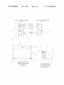
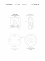
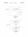
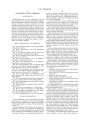
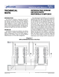
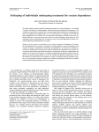
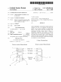
US007350304B2
(12) United States Patent
(10) Patent N0.:
(45) Date of Patent:
Van Luchene
(54)
US 7,350,304 B2
AUTOMATED LEVELING APPARATUS
6,987,460 B2*
Apr. 1, 2008
1/2006 Tews et a1.
340/689
(75) Inventor: Andrew Stephen Van Luchene, Santa
Fe, NM (Us)
_
* cited by examiner
(73) Ass1gnee: Leviathan Entertainment
Primary ExamineriYaritZa Guadalupe-McCall
(*)
Notice:
Subject to any disclaimer, the term of this
patent is extended or adjusted under 35
(74) Attorney, Agent, or Firm iGonZales Patent Services;
Ellen Gonzales
U.S.C. 154(b) by 127 days.
(57)
(21) Appl. No.: 11/384,650
22
( )
(65)
Pl d:
16
M .20 2006
at
’
Prior Publication Data
Us 2007/0214668 A1
Various embodiments of the present invention provide an
inexpensive and easy to use apparatus and method that
permits a user to attach an apparatus to existing picture
Sep' 20’ 2007
(51)
Int. Cl.
G01C 9/06
frames or other objects With various advantages. Such
embodiments Will keep a picture object or frame in a
s
(2006.01)
3336611
(58)
ABSTRACT
substantially continuously level position or otherwise
aligned position. Thus, using the disclosed apparatus, a user
3336611’
can ensure that any picture, frame or other hanging and
33/366,19, 366,25
See application ?le for complete search history.
relatively ?at object Will generally remain in a pleasantly
horizontal or other desired aspect , Without need for ongoing
Field of Classi?cation Search
(56)
References Cited
user inspection or manual adjustment.
U.S. PATENT DOCUMENTS
6,800,841 Bl *
10/2004 Chou
3 Claims, 5 Drawing Sheets
33/36611
\\v I
new“
U.S. Patent
Apr. 1, 2008
Sheet 1 0f 5
US 7,350 304 B2
F
3\.
xi
U.S. Patent
Apr. 1, 2008
Sheet 2 0f 5
US 7,350 304 B2
\R
.0l.2
U S. Patent
Apr. 1, 2008
aw
Sheet 3 0f 5
US 7,350 304 B2
U S. Patent
Apr. 1, 2008
i
Sheet 4 0f 5
US 7,350,304 B2
U S. Patent
Apr. 1, 2008
Sheet 5 0f 5
US 7,350,304 B2
US 7,350,304 B2
1
2
AUTOMATED LEVELING APPARATUS
position or otherWise Aligned position. Thus, a User can
ensure that any Frame or other hanging and relatively ?at
object Will generally remain in a pleasantly horiZontal or
BACKGROUND
other desired aspect, Without need for ongoing User inspec
tion or manual adjustment.
In some circumstances, various embodiments of the
When hanging items on a Wall or other surface, it is Well
known that such items can become undesirably misaligned.
Such misalignment can detract from the pleasure of vieWing
present invention may be adapted for use in conjunction
With many knoWn devices and, therefore is an improvement
upon, several of the previously knoWn inventions.
Various embodiments of the present invention address the
need to provide a leveling device for existing or traditional
Frames or other objects, and the need to provide for any
the item. Currently, a vieWer is required to move the
misaligned item manually. Without the use a level, a vieWer
may have to approach the item, realign it, and then move a
distance aWay from the item to determine Whether the item
has been moved back to the desired orientation. The vieWer
may have to repeat this process numerous times in order to
accurately move the item to the desired orientation. More
over, such manual alignment can often spark controversy or
ongoing automatic adjustments.
Various embodiments of the present invention address the
problem of a picture hung “out of level” and corrects such
disagreement betWeen multiple vieWers over Whether the
item has, in fact, been returned to proper alignment.
pictures if there is user error upon initial installation or
subsequent manual adjustment of the device(s) or frames.
Various embodiments of the present invention may be
Improved methods for aligning items hung on a Wall or
surface are, therefore, desirable.
readily employed With the millions of existing, popular and
20
BRIEF DESCRIPTION OF THE DRAWINGS
hardWare as depicted in FIG. 1C shoWing a Hook 15 and
Wire 14.
Various embodiments of the present invention Work effec
FIG. 1A is a backside perspective vieW of an embodiment
of the present invention.
FIG. 1B is a side perspective vieW of the embodiment
shoWn in FIG. 1A.
FIG. 1C is a backside perspective vieW of a Frame With
a Leveling Apparatus and Glide Button attached.
FIG. 1D is an enlarged and close-up vieW of the loWer
right hand comer of FIG. 1C.
FIG. 2A is a front perspective vieW of an alternative
25
30
embodiment of the present invention.
35
pictures or other Frames or objects, and methods for use of
such an apparatus. In an embodiment, the device comprises
2. Dual ThroW, Dual Pole Tilt SWitch (or other device(s)
for determining misalignment)
40
3. Direct Current (DC) Motor (or other poWer source or
motor type)
4. Battery (or other poWer source)
sWitch (DPDT).
5. A Wheel attached to the Motor via a Gear
FIG. 3B is a Wiring diagram of an alternative embodiment
45
FIG. 4A is a Wiring diagram for an optional Solar Charger
With a regulation device.
FIG. 4B is a diagram of a dual pole, dual throW (DPDT)
mercury sWitch.
FIG. 5A is a side vieW perspective of a Glide Wheel.
FIG. 5B is a frontal vieW perspective of a Glide Wheel.
FIG. 5C is an angled vieW perspective of a Glide Button
and a Leveling Apparatus attached to a Frame.
FIG. 5D is an angled perspective vieW of a Glide Button.
objects, Without the need for major modi?cations to the
frames or objects, nor changes to Widely accepted practices,
nor any particular skills or craftsmanship by the User.
Various embodiments of the present invention permit a
Frame that is nudged or that is otherWise not properly
Aligned to be automatically returned to its Aligned position.
An embodiment of the present invention includes an
seven main components including a (an):
1. Enclosure
present invention using a single, dual pole, dual throW tilt
using tWo, single pole, dual throW tilt sWitches (SPDT).
tively With existing picture frames and other hanging
apparatus for automatically adjusting and leveling hanging
FIG. 2B is a side perspective vieW of an alternative
embodiment of the present invention.
FIG. 2C is a front perspective vieW of a pressure Wheel
that may be used With the alternative embodiment of the
present invention as shoWn in FIGS. 2A and 2B.
FIG. 2D is a front perspective vieW of a pressure Wheel
that may be used With the alternative embodiment of the
present invention as shoWn in FIGS. 2A and 2B.
FIG. 3A is a Wiring diagram of an embodiment of the
Widely used picture frames and other Frames that are hung
using the Well knoWn and Widely adopted “hook and Wire”
6. Wiring connecting the Tilt SWitch, Battery, Motor and,
if included, Solar Charger.
7. Solar Charger (or other means for recharging a battery
50
55
DETAILED DESCRIPTION
or other poWer source)
It is readily apparent to one of ordinary skill in the art that
various substitutions may be made to the speci?c compo
nents listed immediately above.
When mounted to the loWer right corner (or, e.g., the
loWer left comer With minor and apparent modi?cations) of
a Frame or other object, the apparatus is activated Whenever
the Frame or object becomes misaligned. When either comer
is loWered, the integral Tilt SWitch “senses” this misalign
ment and an electrical circuit is created or closed. This
electrical circuit, in turn, supplies poWer (in the form of an
Various embodiments of the invention relate to an appa
electrical current) to a DC motor, Which causes the DC
motor to turn, Which then turns a Gear that is further attached
ratus that may be attached to, and Which automatically
adjusts and levels, hanging pictures, other square, rectangle
60
or other shaped objects i.e., Frames or Works, and methods
for their use.
Various embodiments of the present invention provide an
inexpensive, and easy to use apparatus and method that
permits a User to attach an apparatus to existing Frames With
to a Wheel. This Wheel is positioned in the apparatus such
that, When attached to the Frame, the Wheel Will come in
direct contact With the adjacent Wall or other stationary
mounting object. When the Wheel turns, the Frame is
moved, e.g., up or doWn, at the corner Where the device is
65
attached, thereby realigning the Frame or object.
various advantages. Such embodiments Will keep a picture
For example, in the event that the loWer right corner of the
or other object or Frame in a substantially continuously level
Frame (or object) is too loW, a Motor turns a Wheel in a
US 7,350,304 B2
4
3
clockwise direction (when viewing the device from the right
side of the Frame), which pushes the lower right comer of
the Frame (or object) up the wall (or along whatever the
switch, pendulum inclinator or tilt switch, “ball in tube”
tilt switch or any solid state, liquid ?lled, electrolytic
Frame or object may be attached).
ing device.
inclinometer/tilt sensor, or any other suitable tilt sens
In the event that the lower right corner of the Frame is too
Motorishall mean a (commercially available or cus
high, the Tilt Switch is engaged such that the polarity of the
tom manufactured) Direct Current (DC) Motor or any
other suitable device(s) that convert electrical current
into mechanical or physical motion.
Solar Chargerishall mean a device (whether such
device is commercially available or custom manufac
current is reversed, causing the motor to turn in a counter
clockwise direction (when viewing the device from the right
side of the frame), which causes the right corner to move
lower in relation to the wall.
In either case, as the Fame (or object or Work) returns to
tured) that is capable of converting sunlight, ambient
proper alignment, e.g., level with the ?oor (or Earth), the Tilt
light, or other light (whether or not considered “visible
light”) or other electromagnetic radiation into an elec
Switch is returned to the “null” position, which opens the
previously established circuit. Without power, the motor
ceases to turn, causing the wheel to stop. In this fashion, the
trical current using one or more transducers (e.g.,
Frame remains in a consistently Aligned position. Further
photovoltaic cells) and may include a regulation device
to prevent overcharging.
more, battery or other electrical power is conserved as such
. The term “product” means any machine, manufacture
power is generally consumed when the Frame is misaligned.
and/or composition of matter, unless expressly speci
An embodiment of the present invention includes a buzzer
or other device capable of generating a sound, which may
?ed otherwise.
20
functioning.
wise.
. Each process (whether called a method, algorithm or
25
Various other embodiments are described.
De?nitions
Terms
a. Alignedishall mean aligned in a desired manner, such
as substantially level with the earth. In an embodiment,
. The term “process” means any process, algorithm,
method or the like, unless expressly speci?ed other
alert the User that the apparatus is functioning.
An embodiment of the present invention includes a Light
Emitting Diode (LED) or other device capable of generating
visible light, which may alert the User that the apparatus is
30
otherwise) inherently includes one or more steps, and
therefore all references to a “step” or “steps” of a
process have an inherent antecedent basis in the mere
recitation of the term ‘process’ or a like term. Accord
ingly, any reference in a claim to a ‘step’ or ‘steps’ of
a process has suf?cient antecedent basis.
. The terms “an embodiment”, “embodiment”, “embodi
ments”, “the embodiment”, “the embodiments”, “one
aligned means that a portion of the object that is desired
or more embodiments”, “some embodiments”, “certain
to be aligned (e.g., a portion such as a bottom horizon
embodiments ,
tal edge) lies substantially in the plane that is normal
(perpendicular) to the axis de?ned by the direction of
ment” and the like mean “one or more (but not all)
35
one embodiment ,
another embodi
embodiments of the disclosed invention(s)”, unless
gravity. This plane is referred to as the “horizontal
plane”. In such an embodiment, the portion of the
. The term “variation” of an invention means an embodi
object (e.g., the bottom edge) would be substantially
ment of the invention, unless expressly speci?ed oth
perpendicular to the axis de?ned by the direction of
gravity, and where the portion de?nes an axis, such an
axis lies substantially in the horizontal plane (but may
form a small angle with respect to the horizontal plane).
expressly speci?ed otherwise.
erwise.
40
m. A reference to “another embodiment” in describing an
embodiment does not imply that the referenced
embodiment is mutually exclusive with another
Thus, ‘aligned’ can mean aligned within a threshold
embodiment (e.g., an embodiment described before the
number of degrees (e.g., within 5 degrees) of a plane
(e.g., the horizontal plane). In other embodiments, an
object or portion of the object is aligned with respect to
referenced embodiment), unless expressly speci?ed
45
The terms “including”, “comprising” and variations
a plane that is not coincident with the horizontal plane.
For example, it may be desirable to align an object or
thereof mean “including but not limited to”, unless
expressly speci?ed otherwise.
portion of an object
b. Userishall mean any person including a person mak
ing use or practicing the various disclosed embodi
ments of the invention.
. The term “consisting of” and variations thereof mean
50
The terms “a”, “an” and “the” mean “one or more”,
unless expressly speci?ed otherwise.
ing or containing something or in which a picture is
The term “plurality” means “two or more”, unless
55
mercial signage or other similar objects that may be
including anything which may be incorporated by
reference”, unless expressly speci?ed otherwise.
d. Workishall mean an object, including but not limited
to, a picture, painting, mirror or poster that is contained
within a Frame or other border materials.
60
e. Tilt Switchishall mean a device (whether or not
. The phrase “at least one of”, when such phrase modi?es
a plurality of things (such as an enumerated list of
things) means any combination of one or more of those
things, unless expressly speci?ed otherwise. For
commercially available or custom manufactured) that
is capable of detecting a change in orientation on a
Single-Pole, Double-Throw (SPDT) mercury tilt
expressly speci?ed otherwise.
. The term “herein” means “in this patent application,
hung, e.g., on a wall or other base.
single axis or on multiple axes. A Tilt Switch may
include, but is not limited to any one (or more, as
necessary or desired) of the following devices: a
“including and limited to”, unless expressly speci?ed
otherwise.
c. Frameishall mean a structure or framework support
mounted, or any other ?xtures, such as a mirror, com
otherwise.
example, the phrase “at least one of a widget, a car and
a wheel” means either (i) a widget, (ii) a car, (iii) a
65
wheel, (iv) a widget and a car, (v) a widget and a wheel,
(vi) a car and a wheel, or (vii) a widget, a car and a
wheel.
US 7,350,304 B2
6
5
. Numerical terms such as “one”, “tWo”, etc. When used
. The terms “determine”, “sense”, “determining”, or
“sensing” does not imply that mathematical processing
as cardinal numbers to indicate quantity of something
(e.g., one Widget, tWo Widgets), mean the quantity
indicated by that numerical term, but do not mean at
least the quantity indicated by that numerical term. For
example, the phrase “one Widget” does not mean “at
least one Widget”, and therefore the phrase “one Wid
get” does not cover, e.g., tWo Widgets.
must be performed, and does not imply that numerical
methods must be used, and does not imply that an
algorithm or process is used.
. The terms “determine”, “sense”, “determining”, or
“sensing” does not imply that any particular device
must be used. For example, a computer need not
necessarily perform the determining or sensing.
. The phrase “based on” does not mean “based only on”,
unless expressly speci?ed otherWise. In other Words,
the phrase “based on” describes both “based only on”
Forms of Sentences
and “based at least on”.
The term “represent” and like terms are not exclusive,
a. Where a limitation of a ?rst claim Would cover one of
a feature as Well as more than one of a feature (e.g., a
limitation such as “at least one Widget” covers one
unless expressly speci?ed otherWise. For example, the
Widget as Well as more than one Widget), and Where in
term “represents” does not mean “represents only”,
a second claim that depends on the ?rst claim, the
unless expressly speci?ed otherWise. In other Words,
second claim uses a de?nite article “the” to refer to the
the phrase “the data represents a credit card number”
describes both “the data represents only a credit card
number” and “the data represents a credit card number
limitation (e.g., “the Widget”), this does not imply that
and the data also represents something else”.
20
W. The term “Whereby” is used herein only to precede a
clause or other set of Words that express only the
. Each claim in a set of claims has a different scope.
intended result, objective or consequence of something
that is previously and explicitly recited. Thus, When the
term “Whereby” is used in a claim, the clause or other
Words that the term “Whereby” modi?es do not estab
lish speci?c further limitations of the claim or other
Wise restricts the meaning or scope of the claim.
x. The term “e.g.” and like terms means “for example”,
and thus does not limit the term or phrase it explains.
25
30
. When an ordinal number (such as “?rst”, “second”,
“third” and so on) is used as an adjective before a term,
that ordinal number is used (unless expressly speci?ed
otherwise) merely to indicate a particular feature, such
(e.g., instructions, a data structure) over the Internet”,
Internet. HoWever, both “instructions” and “a data
structure” are merely examples of “data”, and other
things besides “instructions” and “a data structure” can
be “data”.
Therefore, for example, Where a limitation is explicitly
recited in a dependent claim, but not explicitly recited
in any claim from Which the dependent claim depends
(directly or indirectly), that limitation is not to be read
into any claim from Which the dependent claim
depends.
For example, in the sentence “the computer sends data
the term “e.g.” explains that “instructions” are an
example of “data” that the computer may send over the
Internet, and also explains that “a data structure” is an
example of “data” that the computer may send over the
the ?rst claim covers only one of the feature, and this
does not imply that the second claim covers only one of
the feature (e.g., “the Widget” can cover both one
Widget and more than one Widget).
as to distinguish that particular feature from another
35
40
y. The term “i.e.” and like terms means “that is”, and thus
feature that is described by the same term or by a
similar term. For example, a “?rst Widget” may be so
named merely to distinguish it from, e.g., a “second
Widget”. Thus, the mere usage of the ordinal numbers
“?rst” and “second” before the term “Widget” does not
indicate any other relationship betWeen the tWo Wid
gets, and likeWise does not indicate any other charac
teristics of either or both Widgets. For example, the
limits the term or phrase it explains. For example, in the
mere usage of the ordinal numbers “?rst” and “second”
sentence “the computer sends data (i.e., instructions)
before the term “Widget” (1) does not indicate that
over the Internet”, the term “i.e.” explains that “instruc
tions” are the “data” that the computer sends over the
Internet.
either Widget comes before or after any other in order
45
Determining/Sensing
a. The terms “determine”, “sense”, “determining”, or
“sensing” and grammatical variants thereof (e.g., to
determine a price, determining a value, sensing an
angle, determine an object Which meets a certain cri
terion) is used in an extremely broad sense. The terms
50
“determine” “sense” “determining” or “sensing”
encompasses a Wide variety of actions and therefore
can include calculating, computing, processing, exam
ining, deriving, investigating, looking up (e.g., looking
ascertaining and the like. Also, “determine”, “sense”,
“determining”, or “sensing” can include receiving (e.g.,
60
in a memory), the closing an electrical circuit” and the
. When a single device or article is described herein,
more than one device/article (Whether or not they
cooperate) may alternatively be used in place of the
single device/article that is described. Accordingly, the
functionality that is described as being possessed by a
device may alternatively be possessed by more than
one device/article (Whether or not they cooperate).
like and can also include resolving, selecting, choosing,
establishing, and the like.
. Similarly, Where more than one device or article is
described herein (Whether or not they cooperate), a
single device/article may alternatively be used in place
. The terms “determine”, “sense”, “determining”, or
“sensing” does not imply certainty or absolute preci
sion, and therefore can include estimating, predicting,
guessing and the like.
beloW any other, as in importance or quality. In addi
tion, the mere usage of ordinal numbers does not de?ne
a numerical limit to the features identi?ed With the
ordinal numbers. For example, the mere usage of the
ordinal numbers “?rst” and “second” before the term
“Widget” does not indicate that there must be no more
than tWo Widgets.
55
up in a table, a database or another data structure),
receiving information), accessing (e.g., accessing data
or location; (2) does not indicate that either Widget
occurs or acts before or after any other in time; and (3)
does not indicate that either Widget ranks above or
65
of the more than one device or article that is described.
For example, a plurality of computer-based devices
may be substituted With a single computer-based
US 7,350,304 B2
8
7
device. Accordingly, the various functionality that is
g. Although process steps, algorithms or the like may be
described in a sequential order, such processes may be
con?gured to work in different orders. In other words,
any sequence or order of steps that may be explicitly
described does not necessarily indicate a requirement
that the steps be performed in that order. On the
contrary, the steps of processes described herein may be
performed in any order practical. Further, some steps
described as being possessed by more than one device
or article may alternatively be possessed by a single
device/article.
f. The functionality and/or the features of a single device
that is described may be alternatively embodied by one
or more other devices which are described but are not
explicitly described as having such functionality/fea
tures. Thus, other embodiments need not include the
may be performed simultaneously despite being
described device itself, but rather can include the one or
described or implied as occurring non-simultaneously
(e.g., because one step is described after the other step).
Moreover, the illustration of a process by its depiction
in a drawing does not imply that the illustrated process
is exclusive of other variations and modi?cations
thereto, does not imply that the illustrated process or
more other devices which would, in those other
embodiments, have such functionality/features.
Disclosed Examples and Terminology Are Not Limiting
a. Numerous embodiments are described in this patent
application, and are presented for illustrative purposes
only. The described embodiments are not, and are not
any of its steps are necessary to the invention, and does
intended to be, limiting in any sense. The presently
disclosed invention(s) are widely applicable to numer
ous embodiments, as is readily apparent from the
disclosure. One of ordinary skill in the art will recog
niZe that the disclosed invention(s) may be practiced
with various modi?cations and alterations, such as
structural, logical, software, and electrical or electro
not imply that the illustrated process is preferred.
h. Although a process may be described as including a
20
tion(s) include other processes that omit some or all of
the described steps. Unless otherwise speci?ed explic
mechanical modi?cations. Although particular features
of the disclosed invention(s) may be described with
plurality of steps, that does not imply that all or any of
the steps are essential or required. Various other
embodiments within the scope of the described inven
25
itly, no step is essential or required.
i. Although a product may be described as including a
reference to one or more particular embodiments and/or
plurality of components, aspects, qualities, character
drawings, it should be understood that such features are
istics and/or features, that does not indicate that all of
the plurality are essential or required. Various other
embodiments within the scope of the described inven
tion(s) include other products that omit some or all of
not limited to usage in the one or more particular
embodiments or drawings with reference to which they
are described, unless expressly speci?ed otherwise.
30
the described plurality.
j. Unless expressly speci?ed otherwise, an enumerated list
. The present disclosure is neither a literal description of
all embodiments of the invention nor a listing of
features of the invention which must be present in all
embodiments.
. Neither the Title (set forth at the beginning of the ?rst
page of this patent application) nor the Abstract (set
forth at the end of this patent application) is to be taken
as limiting in any way as the scope of the disclosed
invention(s). An Abstract has been included in this
application merely because an Abstract of not more
of items (which may or may not be numbered) does not
imply that any or all of the items are mutually exclu
35
sive. Therefore it is possible, but not necessarily true,
that something can be considered to be, or ?t the
de?nition of, two or more of the items in an enumerated
list. Also, an item in the enumerated list can be a subset
(a speci?c type of) of another item in the enumerated
40
than 150 words is required under 37 C.F.R. § l.72(b).
. The title of this patent application and headings of
list. For example, the enumerated list “a computer, a
laptop, a PDA” does not imply that any or all of the
three items of that list are mutually exclusiveie.g., an
sections provided in this patent application are for
item can be both a laptop and a computer, and a
convenience only, and are not to be taken as limiting
the disclosure in any way.
“laptop” can be a subset of (a speci?c type of) a
45
“computer”.
. Devices that are described as in communication or
k. Likewise, unless expressly speci?ed otherwise, an
otherwise connected with each other need not be in
continuous communication or connection with each
enumerated list of items (which may or may not be
numbered) does not imply that any or all of the items
are collectively exhaustive or otherwise comprehensive
of any category. For example, the enumerated list “a
other, unless expressly speci?ed otherwise. On the
contrary, such devices need only transmit or be other
50
computer, a laptop, a PDA” does not imply that any or
all of the three items of that list are comprehensive of
wise connected to each other as necessary or desirable,
and may actually refrain from exchanging data or
electrical current most of the time. For example, a
machine in communication with another machine via
the Internet may not transmit data to the other machine
for a prolonged period (eg weeks at a time). In
addition, devices that are in communication with each
any category.
1. Further, an enumerated listing of items does not imply
55
the order in which they are enumerated.
Computing
other may communicate directly or indirectly through
a. It will be readily apparent to one of ordinary skill in the
art that the various processes described herein may be
one or more intermediaries.
f. A description of an embodiment with several compo
that the items are ordered in any manner according to
60
implemented by, e.g., appropriately programmed gen
nents or features does not imply that all or even any of
eral purpose computers and computing devices. Typi
such components/features are required. On the con
trary, a variety of optional components are described to
cally a processor (e.g., one or more microprocessors,
illustrate the wide variety of possible embodiments of
the present invention(s). Unless otherwise speci?ed
explicitly,
required.
no
component/feature is
essential
or
one or more microcontrollers, one or more digital
signal processors) will receive instructions (e.g., from
65
a memory or like device), and execute those instruc
tions, thereby performing one or more processes
de?ned by those instructions.
US 7,350,304 B2
9
10
required, embodiments of a computer-readable medium
b. A “processor” means one or more microprocessors,
central processing units (CPUs), computing devices,
storing a program or data structure include a computer
microcontrollers, digital signal processors, or like
readable medium storing a program that, When
devices or any combination thereof.
c. Thus a description of a process is likeWise a description
executed, can cause a processor to perform some (but
not necessarily all) of the described process.
j. Where databases are described, it Will be understood by
one of ordinary skill in the art that (i) alternative
of an apparatus for performing the process. The appa
ratus can include, e.g., a processor and those input
devices and output devices that are appropriate to
database structures to those described may be readily
perform the method.
d~ Further: Programs that implement such methods (as to
Well aS Other types of data) may be Stored and transihitted using a Variety of media (eg, eOihPuter read-
employed, and (ii) other memory structures besides
databases may be readily employed. Any illustrations
or descriptions of any sample databases presented
herein are illustrative arrangements for stored repre
able media) in a number of maImefS- In some embodiments, hard-Wired circuitry or custom hardWare may be
used in place of, or in combination With, some or all of 15
the Software instructions that Can implement the Piecesses of various embodiments. Thus, various combinations of hardware and Software may he used instead
sentations of information. Any number of other
arrangements may be employed besides those Sug
gested by, age tables illustrated in drawings or else
Where. Similarly, any illustrated entries of the databases
represent exemplary information only; one of Ordinary
skill in the art Will understand that the number and
Of SO?Ware 01‘ hardware only.
- The term “Computer-readable medium” refers to any 20
content of the entries can be different from those
described herein. Further, despite any depiction of the
medium that Participates in Providing data (e'g's
inSImCIiOnS, data Structures) Which may be read by a
databases as tables, other formats (including relational
databases, object-based models and/or distributed data
eOihPuteh a PieceSSOr Or a like deViee- Siieh a medium
bases) are Well knoWn and could be used to store and
may take many forms, including but not limited to,
manipulate the data types described herein. LikeWise,
non-volatile media, volatile media, and transmission 25
Object methods or behaviors of a database can be used
media- NOB-Volatile media include, for example, 0Ptical or magnetic disks and other persistent memory.
Volatile media ihehide dyhaihie iahdeih aeeess
memory (DRAM), Which typically constitutes the main
to implement various processes, such as the described
herein In addition, the databases may, in a known
manner, be stored locally or remotely from any device
(5) which access data in the database,
memory. Transmission media include coaxial cables, 30
_ Various embodiments can he Con?gured tO Work in a
Copper Wire and hher epttes’ thehtdthg the wires that
comprise a system bus coupled to the processor. Trans-
netWork environment including a computer that is in
Communication (eg via a Communications network)
mission media may include or convey acoustic Waves,
With one or more deviees_ The computer may eemmu_
hght Waves and electromagnetic ehhsstehs, Sheh as
nicate With the devices directly or indirectly, via any
those generated durmg rad1o frequency (RF) and mfra- 35
Wired or Wireless medium (eg the Internet, LAN’
red (IR) data eommhhieattehs~ Cehhheh terms of Com‘
WAN or Ethernet, Token Ring, a telephone line, a cable
Phter'readahie ihedia ihethdea for example’ a ?oppy
dish, a hexthte disk’ hard dtsk’ maghette tape’ ahy ether
line, a radio channel, an optical communications line,
commercial on-line service providers, bulletin board
maghetie medium: aCD'ROM’ DVD’ any other eptteat
thedhlhh Phheh eards> Paper tape’ ahy ether physteat 40
systems, a satellite communications link, a combina
tion of any of the above). Each of the devices may
medium With PatternS of holes’ a RAM’ a PROM’
themselves comprise computers or other computing
EPROh/h a FLASH'EEPROM’ ahy ether htehtery ehtp
devices, such as those based on the Intel® Pentium® or
or cartridge, a carrier Wave as described hereinafter, or
CentrinOTM processor’ that are adapted to Communicate
any other medium from Which a computer can read.
With the eemputeh Any number and type of devices
. Various forms of computer readable media may be 45
involved
in carrying data (eg sequences of instruc.
.
Hons) to a processor‘ For example’ data may be (1)
.
may he in Communication With the eemputeh
In an embodiment , a Server Computer or centra1-1Zed
authority may not be necessary or desirable For
delivered from RAM to a processor; (ii) carried over a
1 the resent invention ma
Examp
e.’
p
e pract1ced on one
or protocols, such as Ethernet (or IEEE 802.3), SAP,
authority. In such an embodiment, any functions
described herein as performed by the server computer
transm1tted according to numerous formats, standards 50
ATP, Bluetooth, and TCP/IP, TDMA, CDMA, and 3G;
and/or (iv) encrypted to ensure privacy or prevent fraud
in any of a variety of Ways Well knoWn in the art.
g. Thus a description of a process is likeWise a description 55
of a computer-readable medium storing a program for
performing the process. The computer-readable
medium can store (in any appropriate format) those
program elements Which are appropriate to perform the
method.
60
h. Just as the description of various steps in a process does
not indicate that all the described steps are required,
embodiments of an apparatus include a computer/
computing device operable to perform some (but not
necessarily all) of the described process.
i. LikeWise, just as the description of various steps in a
process does not indicate that all the described steps are
.y’
in an embodiment
Wireless. transmission
medium; (iii) formatted and/or
.
.
’
or more dev1ces W1thout a central
or data described as stored on the server computer may
instead be performed by or stored on one or more such
devices.
Continuing Applications
a. The present disclosure provides, to one of ordinary skill
in the art, an enabling description of several embodi
ments and/or inventions. Some of these embodiments
and/or inventions may not be claimed in this patent
application, but may nevertheless be claimed in one or
more continuing applications that claim the bene?t of
priority of this patent application. Applicants intend to
?le additional applications to pursue patents for subject
65
matter that has been disclosed and enabled but not
claimed in this patent application.
35 U.S.C. § 112, paragraph 6
US 7,350,304 B2
11
12
prevent the Frame 17 from remaining in a misaligned state.
Tilt SWitches 2, also knoWn as inclinometers, are Well
knoWn and Widely used, and are appropriate for use in
a. In a claim, a limitation of the claim Which includes the
phrase “means for” or the phrase “step for” means that
35 U.S.C. § 112, paragraph 6, applies to that limitation.
various embodiments of the present invention and are com
b. In a claim, a limitation of the claim Which does not
mercially available in a variety of styles and types, With and
include the phrase “means for” or the phrase “step for”
means that 35 U.S.C. § 112, paragraph 6 does not apply
to that limitation, regardless of Whether that limitation
Without the use of mercury, other liquid electrolyte or other
conductors. Therefore, only a brief description of generic tilt
sWitches Will be provided beloW. By Way of example, one
recites a function Without recitation of structure, mate
rial or acts for performing that function. For example,
suitable tilt sWitch to be used herein is a mercury tilt sWitch
in a claim, the mere use of the phrase “step of’ or the
phrase “steps of’ in referring to one or more steps of the
claim or of another claim does not mean that 35 U.S.C.
that is manufactured by RXR Electronics of Avenel, N]. as
Part No. 1700TLMC. Another alternative Would be use of a
single or dual tilt sensors manufactured by Signal Quest of
Lebanon NH, as Part No. SQ-SEN-OOlP/OOIPS. Various
alternative part selections and implementations are readily
§ 112, paragraph 6, applies to that step(s).
c. With respect to a means or a step for performing a
speci?ed function in accordance With 35 U.S.C. § 112,
paragraph 6, the corresponding structure, material or
acts described in the speci?cation, and equivalents
herein and is ideally suited for use With various embodi
thereof, may perform additional functions as Well as the
ments.
apparent to anyone skilled in the art. HoWever, a neW
Dual-Pole, Double-Throw (DPDT) Tilt SWitch is disclosed
Alternatively, single or dual, solid-state single or dual axis
speci?ed function.
d. Computers, processors, computing devices and like
20
products are structures that can perform a Wide variety
inclinometers could be used such as those manufactured by
Spectron of Hauppauge, NY. as Part No. TAD II. This
of functions. Such products can be operable to perform
option provides for a threshold, Which may be adjusted by
a speci?ed function by executing one or more pro
the user, and this threshold may determine the target angle,
Which is deemed the horiZontal, or other desired angle of
grams, such as a program stored in a memory device of
that product or in a memory device Which that product
accesses. Unless expressly speci?ed otherWise, such a
program need not be based on any particular algorithm,
25
alignment.
30
determine an inclination With respect to the horiZontal (i.e.
the plane that is normal to the axis de?ned by the direction
of gravity or other angle of desired alignment) exist and are
Well knoWn to those skilled in the art.
In an embodiment, a dual throW, dual pole sWitch such as
that described above and further de?ned beloW and in
Diagram 4.!) Would be employed as a component of the
Other types of inclinometers, and other devices, Which
such as any particular algorithm that might be disclosed
in this patent application. It is Well knoWn to one of
ordinary skill in the art that a speci?ed function may be
implemented via different algorithms, and any of a
number of different algorithms Would be a mere design
choice for carrying out the speci?ed function.
disclosed apparatus.
e. Therefore, With respect to a means or a step for
performing a speci?ed function in accordance With 35
U.S.C. § 112, paragraph 6, structure corresponding to a
35
bracket With screW holes 27 is af?xed to the casing 19 to
enable the Leveling Apparatus to be attached to the rear of
speci?ed function includes any product programmed to
perform the speci?ed function. Such structure includes
programmed products Which perform the function,
regardless of Whether such product is programmed With
(i) a disclosed algorithm for performing the function,
(ii) an algorithm that is similar to a disclosed algorithm,
or (iii) a di?ferent algorithm for performing the func
tion.
Disclaimer
40
apparatus to the Frame 17 Without penetrating the Frame 17,
or permanently or otherWise marring and/or damaging the
45
description of embodiments Which all include a par
50
avoWal of embodiments Which do not include that
trically conductive metal ball) is carried Within the holloW
Description of Various Embodiments
55
hoWever, that there is no intention to limit the invention to
60
tion is to cover all modi?cations, alternative constructions,
substituted materials, devices or electrical components, Wir
ing, and the like including any and all equivalents falling
Within the spirit and scope of the claims.
Referring concurrently to FIGS. 1 and 3 of the draWings,
details are provided for an apparatus, Which, as designed, is
responsive to changes in angle of the Frame 17, so as to
angled slightly upWard relative to the center section of the
vial. A supply of mercury 9 or any other suitable electrically
conductive liquid (or other conductor such as, e.g., a elec
particular feature.
the speci?c form disclosed, but, on the contrary, the inven
Frame 17.
As shoWn in the embodiment depicted in FIG. 4B, the
control Tilt SWitch includes a holloW glass vial 10 that is
suspended at the interior of the outer casing 20. The vial is
shoWn having left and right chambers 21 and 22 that are
di?ferent embodiments, and similarly references to the
While the invention is susceptible to various modi?ca
tions and alternative constructions, certain illustrated
embodiments thereof have been shoWn in the draWings and
Will be described beloW in detail. It should be understood,
the picture Frame 17 or other object to be aligned.
In another embodiment, Casing 19 may include dual
sided adhesive tape 25 (FIG. 1B) instead of a mounting
bracket and screW holes 27, Which may be used to secure the
a. Numerous references to a particular embodiment does
not indicate a disclaimer or disavoWal of additional,
ticular feature does not indicate a disclaimer or dis
The Motor 3 and Tilt sWitch 2 shoWn in FIGS. 1A-1D is
enclosed by an outer protective casing 19. A mounting
vial 10. First ends of a dual pair of electrical sWitch contacts
11 and 12 are separated from one another at the interior of
the vial 10 at either end 21 and 22 of the chamber 20 thereof.
The opposite ends of sWitch contacts 11 and 12 are con
nected to respective electrical Wires as more fully described
in FIGS. 3A and 3B. The electrical Wires 11 and 12 complete
the aforementioned control circuit so that the Tilt SWitch 2
and the Motor 3 may be connected in an electrical series
With one another to control the operation of the Motor 3 in
a manner that Will be disclosed further beloW and as depicted
in the Wiring diagrams in FIGS. 3A and 3B.
65
By connecting a Tilt SWitch(es) 2, Motor 3, Battery 4,
Pressure Wheel 5, Gear 6, With Wiring according to FIG. 3A
or, FIG. 3B (as appropriate, or With other Wiring assemblies
US 7,350,304 B2
13
14
that Would be readily apparent to anyone skilled in the art)
the resulting apparatus can be attached to, e.g., the bottom
right edge of any picture, Frame, Work or object. Once in
minimum While providing ample poWer to perform accept
ably Within the target environment.
place, With a charged battery or other poWer source installed
or attached, the apparatus Will automatically adjust a Frame
17, e.g., up or doWn until the Frame is realigned as desired.
accomplished via the folloWing method or steps: A Frame
17, such as that depicted in FIG. 1C is ?rst modi?ed by
In an embodiment, use of the apparatus by a User can be
attaching the Leveling Apparatus to the loWer portion of the
Note that Wheel 5 may or may not include materials to aid
backside (i.e., the side facing to the Wall or adjacent mount
in generating traction or friction. For example, Wheel 5 may
ing surface or structure, When the picture is hung), right edge
be constructed of semi-pliable or hard plastic or rubber or it
may have a rubber coating or layer, or groves or treads to aid
of the Frame 17. This may be accomplished using double
sided adhesive tape 25 as seen in FIG. 1B, other forms of
adhesive (either permanent or temporary), or With small
in generating friction. Other coatings on the Wheel may be
employed to generate appropriate amounts of friction With
the applicable surfaces, and/or the Wheel 5 may be com
posed of other materials to generate appropriate amounts of
friction With the applicable surfaces.
Upon closer inspection of FIGS. 3A and 3B, anyone
skilled in the art Will notice that both Motor 3 electrical
contacts are connected to both positive and negative Wiring
posts, Which is ultimately attached to Battery 4. With proper
installation of the Tilt SWitch(es) 2, it Will be readily
apparent that only a single circuit can be engaged (or closed)
at any given moment depending upon the angle of inclina
tion of the Tilt SWitch(es). This novel arrangement provides
Wood screWs via mounting bracket frame holes 27 as seen in
FIGS. 1A and 1D or With any other method of af?xing,
adhering, connecting or attaching the apparatus to the Fame
17. Many other methods of a?ixing a device, either tempo
rarily or permanently, are Well knoWn Within the prior art.
20
a reversal of polarity, Which permits the apparatus to deliver
selective motion or movement, e.g., to deliver up or doWn
movement of the Frame 17 in a manner Which achieves
25
FIG. 3A assumes the use of a novel Dual Pole, Dual
ThroW Tilt SWitch as further disclosed herein; hoWever, an
30
Double-ThroW (SPDT) Tilt SWitches as seen in FIG. 3B. In
either depicted case, the depicted Wiring ensures that only
one circuit With a given polarity is closed at any given time,
thus protecting the Motor 3 from any electromechanical
failure and only delivering the desired movement of the
35
single Battery 4. As an example, the Battery 4 could be a
single AA battery, such as one manufactured by Energizer of
Wheel 5 to turn clockWise (When facing from the right edge
45
of the frame), Which, in turn, causes the Frame 17 to “rise”
on the right edge and thus the left side to “fall” i.e., loWer.
The movement of the Frame 17 is caused by the combination
of the Wheel 5 turning and friction generated When the
Wheel 5 is resting against a generally solid and generally
Catalog #1 273-258. It Would be apparent to anyone skilled
in the art to construct the disclosed apparatus using a variety
of generally available DC or other motors, tilt sWitches,
batteries or AC poWer supplies, gears, Wheels, Wiring meth
ods, Wires and other electrical and/or mechanical compo
50
nents, adapting the enclosure, motor siZe/horse poWer, bat
tery voltage/amperage, or other poWer supply and other
components to satisfy the apparatus’ intended use, so that
the apparatus provides the required response to a given
Weight and siZe requirement of various available Frames.
By Way of example, but in no Way limiting the general
spirit and scope of the potential of the various embodiments,
it is anticipated that in an embodiment commercial imple
55
unmovable object, such as a Wall. Friction betWeen the
Wheel 5 and a Wall, for example, causes the Frame 17 to
move inversely to the direction of the Wheel 5. To improve
friction, a Wheel 5 may be designed to enhance the friction.
Such enhancement may be accomplished in numerous Ways
including designing the Wheel 5 similarly to those depicted
60
in FIGS. 2C or 2D, Which includes raised portions on the
Wheel’s surface. Moreover, the Wheel 5 may be made of a
soft rubber or other pliable or semi-adhesive compound to
ensure adequate friction While also ensuring that the move
ment of the Wheel 5 does not mar or otherWise damage the
mounting surface such as a Wall.
Once the Frame is returned to the level state or other
desired orientation, i.e., is realigned, the Mercury 9 in the
mentations of an apparatus can be made available in a
accordingly so as to keep the device’s cost and siZe to a
Within the right side of the Tilt SWitch 2, Which, in turn,
causes electrical poWer from the Battery 4 to be supplied to
the Motor 3. This, in turn, causes the Gear 6 to turn the
used such as one manufactured by Danaher Motion of Wood
Dale, Ill. as Part No. 08G. An alternative motor might be one
such as a 1.5-3V DC Metal Gear Motor as manufactured by
Radio Shack of Forth Worth, Tex. as their Model #1 273-258
predetermined number of siZes (e.g., three siZesismall,
medium, and large). With different siZes, it may be desirable
to adjust the components and poWer of each apparatus
prior art.
If the apparatus is installed on the loWer right edge of the
tilted doWn on that same right side and a circuit is closed
40
the speci?cally selected motor type employed including the
motor’s amperage and the voltage requirements.
A 0.7 Watt (or alternative voltage) DC motor could be
Without degrading performance. Many other mechanisms
may be used for causing an electrical connection to be
formed When the tilt sWitch or other sensor is in a misaligned
condition or state, all of Which are Well knoWn Within the
object as described herein, and the Frame 17 is tilted doWn
on that right side, i.e., the right side of the Frame 17 is loWer
than that of the left side, then the Tilt SWitch 2 likeWise is
Frame 17.
In an embodiment the apparatus derives its poWer from a
St. Louis, Mo. as Part No. Energizer Max E91 AAAlkaline
Battery or any other commercially available battery or
batteries as required or desirable in light of criteria such as
turn causes, e. g., the Mercury 9 to come into contact With the
Electrical Leads, e.g., 11 or 12 and a circuit is formed or
closed. The mercury could be replaced With an electrically
conducting metal ball or sphere, Which Would make the Tilt
SWitch shoWn in FIG. 4B more environmentally friendly
alignment.
alternative method is disclosed using tWo Single-Pole,
In an embodiment, When an appropriate Battery 4 is
included (and/or along With an optional poWer sWitch or
other mechanism that controls poWerinot shoWn, that is
turned to the on position or otherWise activated), the appa
ratus is enabled to operate automatically. When the Frame
17 becomes misaligned, the Tilt SWitch 2 is caused to be in
an “out of level” or misaligned condition as Well, Which, in
65
Tilt SWitch 2 (or, e.g., metal ball or other conductor) returns
to its neutral, i.e., “null” or centered position Which causes
the circuit to open, this then causes the Motor 3, Gear 6, and
Wheel 5 to stop turning, While simultaneously conserving
Battery 4 poWer for future usage.
US 7,350,304 B2
15
16
In the case that the right edge of the Frame 17 is too high,
in a similar fashion, the opposite circuit of the Tilt Switch 2,
is closed, thus providing Battery 4 power to the Motor 3 but
may be such that it doesn’t or minimally marks or otherwise
mars the wall or other surfaces, for example, Nylon or
Plastic. Glides such as those used on chairs may be
employed or a custom Glide Button 16 may be appropriate.
Alternatively, instead of a Glide Button 16, a second or other
with reverse polarity (i.e., opposite the polarity used in the
previous example), which, in turn, causes the Motor 3, Gear
6, and Wheel 5 to spin in the opposite (i.e., counter
clockwise) direction, which, in turn, causes the right edge of
number of non-powered Glide Wheels 23 as depicted in
returns to its original alignment, e.g., a level condition, the
circuit is once again opened and the Motor 3 stops, causing
the Frame 17 to stop moving as well.
The Motor 3 is coupled with an appropriate Battery 4 and
Gear 6 so that the Leveling Apparatus is designed to operate
and adjust the Frame 17 slowly, such that the Frame does not
rise and fall (i.e., move up or down on any given edge) too
FIGS. 5A and 5B may be constructed of similar materials to
that of Wheel 5 and could be attached, e.g., to the lower left
backside of the Frame 17 to provide smooth movement of
the edge opposite the apparatus on the Frame 17. A Guide
Wheel 23 would roll freely e.g., up or down in converse
reaction to the movement of the opposite edge of the Frame
17. In the event other orientations, i.e., other than on a
vertical plane, are desired, the Glide Wheel 23 would be
installed in an orientation substantially similar to that of the
quickly and/or endlessly (i.e., “swing” back and forth), but,
af?xed apparatus.
the Frame 17 to “fall” or lower. As before, as the Frame 17
instead, comes to rest as the Frame 17 reaches an Aligned
Referring to FIGS. 2A and 2B, an alternative to the Wheel
state. In this fashion, the Frame 17 is always held in a
constantly Aligned position, without any user observation or
intervention.
One advantage of various embodiments is that there are
5’s orientation is disclosed. The apparatus depicted in FIGS.
2A and 2B works in nearly an identical fashion as that of the
20
embodiment depicted in FIGS. 1A-1D, with one major
modi?cation, i.e., to the orientation of the so-called “pres
sure” Wheel 5. Instead of being mounted such that the
narrow portion of Wheel 5 faces and rests against (or
touches) the wall as in the previously described embodi
25
ment, the ?at or wide portion of the Wheel 5 faces and
no closed circuits when the Frame 17 is level or otherwise
Aligned in a desired position, thereby generally reducing
power consumption and potentially extending Battery 4 life.
Another advantage of various embodiments is the ability to
operate the apparatus without any further User observation
comes into contact with the wall as seen in FIG. 2B using
wheels oriented in a ?at position, relative to the wall or other
mounting surface as seen in FIGS. 2C and 2D using Wheel
5. There are at least four advantages to this orientation of the
or intervention.
Alternative designs to the present invention would be
readily apparent to those skilled in the art, including designs
that maintain a constant supply of current and controlling the
Motor 3 or Wheel 5 via integrated circuits or other computer
30
Wheel 5: 1) By positioning the Wheel 5 so that a larger
surface area of the Wheel 5 is in contact with the wall,
or electromechanical control. One advantage of this design
greater friction may be generated, thereby transferring more
would be to provide the User with more control of the
of the Motor’s 3 energy into vertical (or other desired
directional) movement, 2) the Wheel 5 may have additional
apparatus’ activation thresholds and/or sensitivity, e.g., the
angle at which the device is activated or deactivated, and or
35
to permit User selection and ?nal placement of the device
without mechanical modi?cation, e.g., placing the device in
the lower left, backside edge instead of the lower right,
backside edge.
As mentioned, in an embodiment, the apparatus is placed
on the lower right, backside edge of the Frame 17, however,
anyone skilled in the art would ?nd it readily apparent that
40
the device could be easily used (with minimal or no revi
sions) to operate while positioned at any of the comers (or
even anywhere that is slightly off center) of the Frame 17.
It is generally easier for the apparatus to function (due to
increased leverage) the farther the apparatus is located away
from the center of gravity of the object. Additional embodi
ments may permit the User to change the Leveling Appa
ratus’ orientation and/or speed of operation and/or Tilt
45
abrasive elements added to its larger surface area such as
raised “nubs” or “rings” as depicted in FIGS. 2C and 2D
respectively 3) this alternative position or orientation of
Wheel 5 effectively reduces the overall width of the appa
ratus and, therefore, the distance that the Frame 17 is pushed
away from the wall or other mounting surface and 4) this
reduction in width also effectively changes the relative siZe
of the optional Glide Button(s) and/or Glide Wheel(s), if
used.
Referring to FIG. 4A, an optional enhancement to the
apparatus may be the inclusion of a Solar Charger, which
includes a Photovoltaic Cell 7 that may be positioned and
af?xed to the top edge of the apparatus or the top edge of the
Frame 17, or anywhere ambient or other light may fall. The
Photovoltaic Cell 7 may provide ample power to operate the
50
device without the use of a Battery 4, and/or, to serve as an
Sensor activation point and/or sensitivity. For example,
aid to help extend the useful life of a battery. Moreover, a
speed of Motor 3 rotation may be controlled through the use
55
Charging Regulator 8 may be included in the Solar Charger
to both regulate the charging rate provided by the Photo
voltaic Cell 7 and to guard against overcharging the Battery
4. Simply increasing the length of the wires attached
of a resistor or a variable resistor.
Depending upon the apparatus’ width (e.g., given the
small, medium or large version(s) and/or the type, e.g.,
Wheel or Surface Pressure Wheel models), an optional
supporting device or Glide Button 16 as depicted in FIGS.
5C and SD, of generally the same width as the apparatus may
be af?xed, e.g., on the lower left edge of the Frame 17 that
is opposite the apparatus, e.g., left, so as to prevent the
60
Frame, Work or other object from tilting inward on the edge
opposite the apparatus or to be otherwise unstable against
the wall.
The support device or Glide Button, or other number of
Glide Buttons 16 may be made of any suitable material that
between the Photovoltaic Cell 7 and the apparatus’ enclo
sure 19 (FIG. 1.11) may accomplish remote placement of the
Photovoltaic Cell 7. In this case, additional adhesive tape,
mounting brackets or other hardware, e.g., a separate enclo
sure, may be optionally added to the Solar Charger.
Referring to FIGS. 5C and 5D, as previously mentioned,
the Leveling Apparatus’ width may be countered with the
attachment of a slide or Glide Button 16 or, alternatively as
seen in FIG. 5A and 5B a Glide Wheel 23. Af?xing either
65
device to the Frame 17 in the bottom backside comer,
will balance the Frame properly, i.e., substantially equally
opposite the Leveling Apparatus, e.g., as depicted in FIG.
offsetting the width of the installed apparatus. The material
5C, the Frame 17 will remain equidistant from the wall at
US 7,350,304 B2
17
18
both corners of Frame 17 in an esthetically pleasing position.
An additional bene?t of this arrangement is that the Frame
17 may be more equally distant from the Wall at all four
corners. Finally, adding a Glide Button(s) and/or Glide
Wheel(s) may reduce friction betWeen the Wall and the
corner of the Frame 17 opposite the Leveling Apparatus,
device(s) may add a pleasing effect to the overall operation
of the apparatus such that the User may be made aWare of
the apparatus’ operation and may observe or point out to
other bystanders the apparatus as it automatically aligns the
object or frame. Such optional noti?cation device(s) Would
typically not be an ongoing nuisance as the apparatus Would
Which, in turn, Will reduce poWer requirements, consump
generally be in a stable or aligned position; therefore, the
tion and Wear and tear on the Motor 3.
noti?cation device(s) Would generally only be activated
The Glide Button 16 may be af?xed to the Frame 17 using
adhesive double sided tape 26 as shoWn in FIGS. 5C and 5D
or a Glide Pin (or nail or tack) may be used (not shoWn), or,
absent double sided tape or a pin, it may be af?xed using
When the apparatus is in actual operation.
Additional bene?ts of noti?cation device(s) are: l) in the
event a person or other outside force, such as the Wind,
moves or otherWise disturbs the alignment of a Frame or
commercially available temporary or permanent adhesives.
Glide Button 16 may be made of a plastic resin, nylon or
might prove useful in a personal residence or in an art
other object, a sound and/or light Will be generated, Which
other semi-pliable or ridged material commonly used With
so-called chair glides such as the chair glides manufactured
gallery or museum, 2) such noti?cation device(s) may serve
as a Warning or alarm to deter unauthorized persons from
disturbing valuable items, and 3) should one or more com
by lntemational Equipment Components of Signal Hill,
Calif. e.g., their Light Duty, Nylon Base (round tubing), With
nail (i.e. pin) chair glide, as their Part No. lL22-Rl.
The Glide Wheel 23 may be constructed similarly to the
ponents in the apparatus fail, Which causes the device to
sWing or otherWise fail to achieve the desired alignment, the
20
pressure Wheel 5 and may be of the same or smaller size
than Wheel 5; hoWever it should be constructed in combi
nation With the Glide Wheel Bracket 24 and Glide Wheel
Adhesive Tape 25 such that, in combination, the entire
assembly maintains the Frame 17 at a distance generally
25
equal to the overall Width of the Leveling Apparatus. Glide
Wheel 23 may be af?xed to Frame 17 using Glide Wheel
Adhesive 25, Which may be double sided adhesive tape, or
absent Glide Wheel Adhesive, via a bracket mounting holes
and screWs or nails, using any commercially available Wood
30
screW or other screW or nail of an approximate length, Which
common household electrical plug and poWer converter or
35
40
transformer.
Also, instead of a Wheel 5, other components may be
employed to selectively move a portion of an object (e.g., a
corner of a frame) in a manner that aligns the object (e.g.,
against any ?xed object and controlled thereby.
further comprising a Glide Button that maintains a
Frame equidistant from a Wall or other mounting sur
50
achieve alignment With any arbitrary angle (e.g., a plane that
face.
4. A Leveling Apparatus as de?ned in Embodiment 1,
further comprising and includes a Glide Wheel Mount
ing Bracket.
55
5. A Leveling Apparatus as de?ned in Embodiment 3,
further comprising a Glide Pin.
6. A Leveling Apparatus as de?ned in Embodiment 1,
further comprised of a Photovoltaic Cell or Array
attached to the Leveling Apparatus’ enclosure.
7. A Leveling Apparatus as de?ned in Embodiment 1,
tation or axis, including multiple orientations or axes. Con
as a steady or ?ashing light to the apparatus. The addition of
a buzzer, beeper or other audible and/or visual noti?cation
use of a pressure Wheel placed vertically or horizontally
3. A Leveling Apparatus as de?ned in Embodiment 1,
embodiments of the invention can be readily employed to
modi?cations necessary to add an audible noti?cation device
such as a beeper or buzzer and/or a visual noti?cation such
a. An Enclosure
b. A Tilt SWitch operably connected to the enclosure
c. A Battery in electrical communication With the tilt
sWitch
d. A Direct Current (DC) Motor in electrical commu
nication With the battery; and
capable of automatically adjusting a Frame through the
appropriate diameter or a cylinder of an appropriate diam
sequently, the apparatus may be designed or used to
maintain any desirable alignment as compared With any
?xed point in space.
It Will be readily apparent to anyone With ordinary skill in
the art as to the electrical components, Wiring and other
folloWing enumerated paragraphs.
1. A Leveling Apparatus, comprising:
e. A Wheel attached to the Motor via a Gear
eter and length could replace the Wheel 5.
The principles and apparatus described herein may be
readily employed to maintain an object’s alignment With
forms an angle of ?ve degrees or 90 degrees With the
horizontal plane). It Would be readily apparent to anyone
With ordinary skill in the art that the tilt sWitch may be
manually aligned (or in some cases, electronically or pro
grammatically adjusted or aligned) in any desirable orien
tages speci?ed herein.
2. A Leveling Apparatus as de?ned in Embodiment l,
moves the comer up or doWn). For example, a ball of an 45
other planes besides the horizontal plane. For example,
by Radio Shack of Fort Worth, Tex. as their Model #1
273-054, Catalog #1 273-054. A light could be used such as
a Light Emitting Diode such as one manufactured by Radio
Shack of Fort Worth, Tex. as their Catalog #1 276-350.
It Will thus be apparent that there has been provided in
accordance With the present invention a Leveling Apparatus
With an integrated Tilt SWitch and, ideally, a Dual ThroW,
Dual Pole Tilt SWitch, Which achieves the aims and advan
Additional Embodiments
Additional non-limiting embodiments are provided in the
is less than or substantially less than the depth of the Frame
17 but still of an appropriate length to ensure that the Glide
Wheel 23 remains ?rmly af?xed to Glide Wheel 23 and
Frame 17.
Instead of a DC Motor, various other means for rotating
a Wheel, gear or other components may be substituted for the
DC motor. For example, an AC Motor may be directly
attached to a turning Wheel With poWer supplied via a
noti?cation device may alert the User to such a failure of the
apparatus. A buzzer could be used such as one manufactured
60
further comprised of a Photovoltaic Cell or Array
providing suf?cient excess Wiring to af?x the Photo
voltaic Cell or Array to a point distant from the Lev
eling Apparatus enclosure, including the top or side of
a Frame or to an adjacent Wall or other ?xture or object.
65
8. A Leveling Apparatus as de?ned in Embodiment 1,
further comprised of a Photovoltaic Cell or Array and
a Charging Regulator, Which extends the useful life of
US 7,350,304 B2
19
20
the battery in the Leveling Apparatus and, furthermore,
prevents overcharging the battery.
It Will, of course, be understood that the foregoing
description is of exemplary embodiments of the invention
and that the invention is not limited to the speci?c embodi
ments shoWn. Various changes and modi?cations Will
9. A Leveling Apparatus as de?ned in Embodiment 1,
further comprised of a buZZer or beeper to alert the User
that the Leveling Apparatus is in operation.
become apparent to those skilled in the art and all such
10. A Leveling Apparatus as de?ned in Embodiment 1,
With an integral tilt sWitch capable of user manual
variations and modi?cations are intended to come Within the
spirit and scope of the appended claims.
adjustable threshold and sensitivity settings.
11. A Leveling Apparatus as de?ned in Embodiment 1,
With an integral tilt sWitch capable of user software
What is claimed is:
1. An apparatus comprising:
adjustable threshold and sensitivity settings.
a component for attaching to an object;
a tilt sWitch that is operable to determine if an axis of the
12. A tilt sWitch capable of controlling tWo, or more,
circuits given one angle of declination, comprised of
object is misaligned With a desired axis;
tWo, or more, sets of electrical leads.
13. A Wiring method connected to a Battery, Tilt SWitch
and Motor such that the Motor may only receive
electrical poWer With a given speci?c polarity as con
trolled by a Tilt SWitch capable of controlling the state
of an electrical circuit according to the angle of incli
nation of the switch.
14. AWiring method as de?ned in Embodiment 13, further
comprised of Photovoltaic Cell or Array to provide
a second device that orients the object based on the
determining of the tilt sWitch;
and a poWer source in electrical communication With the
tilt sWitch;
Wherein the second device comprises a Wheel that is in
20
2. The apparatus of claim 1 Wherein the tilt sWitch
comprises a housing With a cylindrical cavity containing a
mobile, electrically conductive material.
additional charging poWer When exposed to ambient
light.
15. AWiring method as de?ned in Embodiment 13, further
comprised of a Charging Regulator that prevents over
charging of the Battery.
16. AWiring method as de?ned in Embodiment 13, further
comprised of a Resistor that regulates the speed of the
Motor.
electrical communication With the poWer source.
25
3. The apparatus of claim 1 Wherein When the tilt sWitch
determines that an axis of the object is misaligned With the
axis of gravity, a circuit is completed betWeen the tilt sWitch,
the poWer source, and the Wheel, such that the Wheel is
rotated so as to return the object to proper alignment.
*
*
*
*
*