1
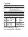
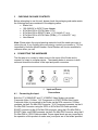
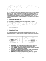
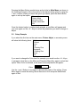
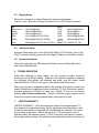
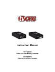
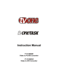
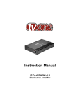
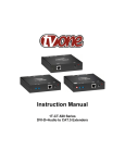
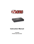
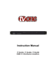
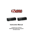
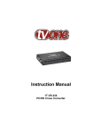
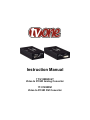
Instruction Manual
1T-V1280HD-ST
Video to PC/HD Analog Converter
1T-V1280DVI
Video to PC/HD DVI Converter
2
Table of Contents
1
Table of Contents .......................................................................................... 3
2
INTRODUCTION ........................................................................................... 4
3
SPECIFICATIONS ......................................................................................... 6
4
CHECKING PACKAGE CONTENTS ............................................................. 7
5
CONNECTING THE HARDWARE ................................................................. 7
6
OPERATING THE UNIT ................................................................................ 8
7
TROUBLESHOOTING ................................................................................. 10
8
LIMITED WARRANTY ................................................................................. 10
9
REGULATORY COMPLIANCE ................................................................... 11
10
CONTACT INFORMATION ...................................................................... 12
1
INTRODUCTION
Thanks for purchasing this TV One-task product from TV One. The 1T-V1280HDST and 1T-V1280DVI are designed to convert Composite or Component Video
to a wide variety of PC and HDTV resolutions. The two units are similar in
operation and specifications, except that the 1T-V1280HD-ST has an analog
output, while the 1T-V1280DVI has a DVI Output. Our professional video
conversion products have been serving the industry for over twenty years. TV
One offers a full line of high quality Seamless Switchers, Video Scalers,
Up/Down/Cross Converters, Analog-Digital Converters (SD/HD-SDI, HDMI, DVI),
Format Converters, Standards Converters, TBC/Frame Synchronizers, Matrix
Routing Switchers, Signal Distribution Amplifiers and Cat.5 Transmission
Systems.
1.1
Liability Statement
Every effort has been made to ensure that this product is free of errors. TV One
cannot be held liable for the use of this hardware or any direct or indirect
consequential damages arising from its use. It is the responsibility of the user of
the hardware to check that it is suitable for his/her requirements and that it is
installed correctly. All rights reserved. No parts of this manual may be
reproduced or transmitted by any form or means electronic or mechanical,
including photocopying, recording or by any information storage or retrieval
system without the written consent of the publisher.
TV One reserves the right to revise any of its hardware and software following its
policy to modify and/or improve its products where necessary or desirable. This
statement does not affect the legal rights of the user in any way.
All third party trademarks and copyrights are recognised. The TV One logo, TV
One-task and CORIO are the registered Trademarks of TV One. All other
trademarks are the property of their respective holders.
1.2
FEATURES
• Ultra Compact, High Performance Units
• Convert Composite, S-Video or YUV Inputs to PC/HD
• Analog or DVI Output versions
• PC and HD Resolutions
• 32Mb Frame Memory
• Integral Picture Adjustments
• On Screen Display for Setup and Adjustment
• Rugged Metal Case
• Locking DC Power Connector for Security
4
1.3
Getting the Best Results
There are many factors affecting the quality of results when scaling video signals.
Some basic precautions will ensure the best possible performance from your
Video Scaler.
•
•
•
•
•
Output display device – The quality of the output signal will depend
largely upon the type and quality of display device used. For instance,
some video projectors just look better than others.
Using Native Resolution – It is always best to set the output
resolution of the scaler to the native resolution and refresh rate of the
display device. This allows our scaler to do most of the work, which
usually results in a superior picture.
Distance between the Video Scaler and the display device – This
plays a major role in the final result. Long distances are possible, but
special measures should be taken in order to avoid cable losses.
These include using high quality (coax-type) VGA cables and Premium
DVI Cables. Line amplifiers may also be necessary.
Output connection cables – Low quality cables are susceptible to
interference. They degrade signal quality due to poor matching and
cause elevated noise levels. Therefore, cables should be of the best
quality. Coax-type computer cables are recommended because of
their superior internal shielding characteristics.
Interference from nearby electrical devices – These can have an
adverse effect on signal quality. For example, an older computer
monitor often emits very high electromagnetic fields that can interfere
with the performance of video equipment in its proximity.
5
2
2.1
SPECIFICATIONS
General Specifications
Input Format
Input Signal Levels
Output Format
Output Signal Levels
Input Connectors
Output Connectors
Control
Information Display
Video Adjustments
Weight
Dimensions–HxWxD
Power Source
2.2
Composite Video, S-Video, RGBS, YPbPr
Composite Video @ 1V p-p, 75Ω S-Video @Y 1V p-p, C 0.7 V
p-p, 75Ω Pb, B-Y, Pr, R-Y @ 0.7V p-p, 75Ω
RGBHV, YPbPr (1T-V1280HD-ST )
Digital RGBHV (1T-V1290DVI)
RGB @ 0.7V p-p, 75Ω. H&V Sync @ 3-5V p-p, TTL
Y @ 1V p-p, 75Ω. Pb, Pr @ 0.7V p-p, 75Ω
Composite Video via RCA, S-Video via 4 Pin DIN,
YUV & SCART via 8-pin Mini-DIN and breakout cables
1T-V1280HD-ST = HD15, 1T-V1280DVI=DVI
Front Panel Buttons
On Screen Display
Brightness, Contrast, Color, Tint, Sharpness, H&V Peaking
680 grams (1.5 lbs)
25x175x100mm (1”x7”x4” )
100~240VAC to [email protected] In-Plug Switching Adapter
Output Signal Specifications
PC Resolutions
640x480
VGA
SVGA
XGA
WXGA
SXGA
UXGA
800x600
1024x768
1280x768
1280x1024
1600x1200
Vert Rate
50, 60,72,75,85,
100,120Hz
50, 56, 60,72,75,85Hz
50, 60,70,75,85Hz
50, 60Hz
50, 60Hz
60Hz
Format
RGBHV
Scan Type
Progressive
RGBHV
RGBHV
RGBHV
RGBHV
RGBHV
Progressive
Progressive
Progressive
Progressive
Progressive
Vert Rate
50,60Hz
50,60Hz
50,60Hz
50,60Hz
Format
YPbPr, RGBHV
YPbPr, RGBHV
YPbPr, RGBHV
YPbPr, RGBHV
Scan Type
Progressive
Progressive
Progressive
Pseudo Interlaced
Interlaced
Progressive
(Note 1)
HDTV Resolutions
720x480
480p
720x576
576p
1280x720
720p
1920x1080
1080i
(Note 2)
1080p
(Note 3)
1920x1080
50, 60Hz
YpbPr, RGBHV
(Note 1)
Note 1 – UXGA and 1080p available only on 1T-V1280HD-ST .
Note 2 - The 1080i Output is actually a doubled 540p signal. It will appear as 1080i
on most displays, however, it is not a true 1080i signal format.
Note 3 - 1T-V1280DVI is digital RGBHV output only without YPbPr output.
6
3
CHECKING PACKAGE CONTENTS
Before attempting to use this unit, please check the packaging and make certain
the following items are contained in the shipping carton:
• Scaler Unit
• 100~240VAC to 5VDC Power Adapter
• 8 Pin Mini-DIN to 3 RCA Cable (YUV)
• 8 Pin Mini-DIN to SCART Cable (1T-V1280HD-ST only)
• 8 Pin Mini-DIN to 4 RCA Cable (RGBs) (1T-V1280HD-ST only)
• User Manual
Note: Please retain the original packing material should the need ever arise to
return the unit. If you find any items are missing, contact your reseller or TV One
immediately. Have the Model Number, Serial Number and Invoice available for
reference when you call.
4
CONNECTING THE HARDWARE
The first step is to connect a video source to the input of the Scaler and to
connect it’s output to a display device. The drawing below is common to both
units and shows the locations of the input and power connectors.
1
4.1
Connecting the Input
Input and Power
Connections
Both the 1T-V1280HD-ST and 1T-V1280DVI Video Scalers can accept
Composite Video, S-Video, YUV Component or SCART RGBs Video inputs.
Composite Video is connected to the Scaler via the RCA connector, S-Video
connects via the 4-Pin Mini-DIN Connector, YUV Component connects via the 8Pin Mini-DIN Connector using the 3RCA to 8-Pin Mini-DIN Cable provided,
SCART connects via the 8-Pin Mini DIN connector using the 8 Pin Mini-DIN to
SCART Cable, and RGBS connects via the 8-Pin Mini-DIN Connector using the 8
Pin Mini-DIN to 4 RCA Cable provided. Proper signal levels are very important to
the operation of this product so make sure your inputs are of the levels specified
7
on page 6. If improper operation of the unit occurs and the unit has power, the
most likely cause of the problem is high or low signal levels or the use of a wrong
input cable.
4.2
Connecting the Output
The 1T-V1280HD-ST Video Scaler can output analog RGBHV or YPbPr formats
up to UXGA and 1080p. RGBHV and YPbPr are both available on the HD-15
output connector. Should a HDTV (YPbPr) output be desired, use an HD-15 to
RCA cable to connect the device’s output to the destination device. The 1TV1280DVI outputs only digital RGBHV format up to SXGA and 1080i via the DVI
connector.
4.3
Connecting Power to the Unit
The Video Scaler is shipped with an In-Plug Power Adapter to convert
100~240VAC@50-60Hz to 5VDC. Connect the DC Output Cord from the Power
Adapter to the back of the unit and then plug the Power Adapter into an AC
Receptacle. When the unit’s front panel Power Switch is turned On, the Power
LED indicator will illuminate.
5
5.1
OPERATING THE UNIT
Controlling the Scaler
The Scaler is controlled via three buttons with status indicated by OSD. The
position of the buttons is slightly different on the two models but the functionality
is the same.
1T- V1280HD-ST -ST
•
•
•
•
1T-V1280DVI
Menu Button: This Button displays the Menu Options via the On
Screen Display on the display device connected to the output.
+ and - Buttons: These Buttons allow navigation within the Menu and
adjustments of the parameters available.
XGA Reset: Simultaneously depressing the – and + buttons returns
settings to factory defaults and sets the output to XGA.
480p Reset: Simultaneously depressing the MENU and - buttons
returns settings to factory defaults and sets the output to 480p.
8
Pressing the Menu Button results brings up the Initial or Main Menu, as shown in
the following illustration. Move the cursor to the desired setup option by using the
+ and – buttons. When you reach the option you desire, press the Menu Button
again to call up that option. Picture Adjust
Display Setup
Advanced Setup
System Information
Exit
Once the desired option is reached and selected, a new Menu will appear and
you once again use the + & - Keys to select the parameter you wish to change or
adjust.
5.2
Setup Example
If you select the first item on the main menu, Picture Adjust, a secondary menu
will show the following items:
Brightness
Contrast
Color
Tint
H Peaking Filter
Sharpness
V Peaking Filter
Reset
Exit
If you want to change the Color level for example, you would use the + & - Keys,
to navigate to that Item on the Menu and Press the Menu Key again to select that
option. When Color is selected, a sub-menu for the adjustment will appear:
Color
48
Use the + and - Buttons to increase or decrease the value of the setting. Press
Menu again to leave the setting. Move the arrow to Exit and press Menu/Enter
again to Exit.
9
5.3
Display Setup
When this is selected, an Output Resolution sub-menu will appear.
Use the + and – Buttons to choose the desired PC or HDTV output resolution
PC
UXGA (Note 1)
SXGA
WXGA
XGA
SVGA
1600x1200@60Hz
1280x1024@50/60Hz
1280x768@50/60Hz
1024x768@50/60/70/75/85Hz
800x600@50/56/60/72/75/85Hz
VGA
640x480@50/60/72/75/85/100/120Hz
HDTV
720p
576p
480p1080i
1080p
1280x720@50/60Hz
720x576@50Hz
720x480@60Hz
1920x1080@50/60Hz
1920x1080@50/60Hz
(Note 1)
5.4
Note1–1T-V1280HD-ST Only
Advanced Setup
Advance Setup allows you to turn off the Film Mode (3:2 Pull Down), turn off the
OSD (On Screen Display) and set the “No Signal” Display to either Blue or Black.
5.5
System Information
When this is selected, the OSD shows the Scaler’s current Output Resolution
and Vertical Refresh Rate.
6
TROUBLESHOOTING
Other than checking for faulty cables, the only common problem would be
choosing a wrong Output Setting. Make sure the display is capable of handling
the resolution and refresh rate selected and make sure the output format
selected (RGB or YPbPr) for the type of cable being used at the output.
After trying the above suggestions should the problem still persist, contact your
dealer for additional suggestions before contacting TV One. Should the dealer’s
technical personnel be unable to assist you, contact TV One via our support
website: http://tvone.crmdesk.com. Create a technical support request on the
site and our support team will respond within a short period of time.
7
LIMITED WARRANTY
LIMITED WARRANTY – With the exceptions noted in the next paragraph, TV
One warrants the original purchaser that the equipment it manufactures or sells
will be free from defects in materials and workmanship for a period of two years
from the date of purchase. Should this product, in TV One’s opinion, prove
defective within this warranty period, TV One, at its option, will repair or replace
this product without charge. Any defective parts replaced become the property of
10
TV One. This warranty does not apply to those products which have been
damaged due to accident, unauthorized alterations, improper repair,
modifications, inadequate maintenance and care, or use in any manner for which
the product was not originally intended.
Items integrated into TV One products that are made by other manufacturers,
notably computer hard drives and liquid crystal display panels, are limited to the
term of the warranty offered by the respective manufacturers. Such specific
warranties are available upon request to TV One.
If repairs are necessary under this warranty policy, the original purchaser must
obtain a Return Authorization Number from TV One and return the product to a
location designated by TV One, freight prepaid. After repairs are complete, the
product will be returned, freight prepaid.
LIMITATIONS - All products sold are "as is" and the above Limited Warranty is in
lieu of all other warranties for this product, expressed or implied, and is strictly
limited to two years from the date of purchase. TV One assumes no liability to
distributors, resellers or end-users or any third parties for any loss of use,
revenue or profit.
TV One makes no other representation of warranty as to fitness for the purpose
or merchantability or otherwise in respect of any of the products sold. The
liability of TV One with respect to any defective products will be limited to the
repair or replacement of such products. In no event shall TV One be responsible
or liable for any damage arising from the use of such defective products whether
such damages be direct, indirect, consequential or otherwise, and whether such
damages are incurred by the reseller, end-user or any third party.
8
REGULATORY COMPLIANCE
The 1T-V1280HD-ST -ST and 1T-V1280DVI have been tested for compliance
with appropriate FCC and CE rules and regulations.
The Power Adaptor/Supply has been tested for compliance with appropriate UL,
CUL, CE, PSE, GS Rules, Regulations and/or Guidelines.
This Product and Power Adapter is RoHS Compliant.
11
9
CONTACT INFORMATION
Should you have questions or require assistance with this product in areas not
covered by this manual, please contact TV One at the appropriate location.
TV One USA
2791 Circleport Drive
Erlanger, KY 41018
USA
Tel 859-282-7303
Fax 859-282-8225
[email protected]
www.tvone.com
TV One Europe
Continental Approach
Westwood Industrial Estate
Margate, Kent CT9 4JG, UK
Tel +44 (0)1843 873311
Fax +44 (0)1843 873312
[email protected]
www.tvone.eu
TV One Latin America
6991 NW 82 Avenue #8
Miami, FL 33166
USA
Tel 305-396-6275
Fax 305-418-9306
[email protected]
www.tvonela.com
TV One Mercosur
Honduras 5849, 2nd Floor, Office C
(C1414BNI) Capital Federal
Buenos Aires, Argentina
Tel +54 11 4771-5570
Fax +54 11 4771-5570
[email protected]
www.tvonela.com
TV One Asia
11F, NO.28, Sec. 2
San-Min Rd, Panchiao City
Taipei Hsien 220
Taiwan R.O.C.
Tel +886 2 8951-0674
Fax +886 2 8951-0675
[email protected]
www.tvoneasia.com
TV One China
Room 1007, Golden Peach Building
No. 1900 Shangcheng Road
Pudong, Shanghai
China 200120
Tel +86 21 5830-2960
Fax +86 21 5851-7949
[email protected]
10 www.tvonechina.com
End of Manual
12