1
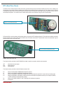
All Mikroelektronika’s development systems feature a large number of peripheral
modules expanding microcontroller’s range of application and making the
process of program testing easier. In addition to these modules, it is also
possible to use numerous additional modules linked to the development system
through the I/O port connectors. Some of these additional modules can operate
as stand-alone devices without being connected to the microcontroller.
Manual
Additional Board
RTC Board
™
MikroElektronika
RTC (Real-Time Clock)
A real-time clock is used to keep the real time and date, generate interrupt and provide timer and alarm functions. Due to a battery cell,
the operation of the real-time clock is enabled even when the microcontroller’s power supply goes off. The real-time clock is linked to
a development system via a 2x5 female connector provided on the RTC board and a 2x5 male connector provided on the I/O port of
the development system. The real-time clock communicates with the microcontroller using I2C serial communication.
DIP switch SW1 is used to select a development
system to connect the RTC board to
Figure 1: RTC board
DIP switch SW1 is used to select a development system to connect the RTC additional board to. This switch also enables connection
between the SDA, SCL and INT-RTC pins provided on the RTC board and a serial I2C module built into the microcontroller. Figure 3
shows the pinout of the DIP switch SW1.
2x5 female connector enables the additional board
to be connected to a development system
Figure 2: RTC board’s bottom view
The function of pins provided on the PCF8583P circuit that is used for connection with the microcontroller:
INT
SCL
SDA
- Open drain interrupt output
- Serial clock line
- Serial data line
The function of pins provided on the 2x5 female connector CN1:
P0 P1
P2
P3
P4
P5
- SCL pin for EasyAVR and BIGAVR development systems;
- SDA pin for EasyAVR and BIGAVR development systems;
- SCL pin for BIGdsPIC, dsPICPRO, LV32MX and LV24-33 development systems; It is also used as an interrupt pin;
- SDA pin for BIGdsPIC, dsPICPRO, LV32MX and LV24-33 development systems and SCL pin for EasyPIC, BIGPIC, LV18FJ and EasyLV18 development systems;
- SDA pin for EasyPIC, BIGPIC, LV18FJ and EasyLV18 development systems;
- Interrupt pin;
MikroElektronika
Figure 3: RTC board connection schematic
Figure 4: RTC board connected to a development system
MikroElektronika
If you have any questions, comments or business proposals, do not hesitate to contact us at [email protected]
If you are experiencing some problems with any of our products or just need additional information, please place your ticket at
www.mikroe.com/en/support
If you want to learn more about our products, please visit our website at www.mikroe.com