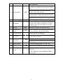
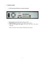
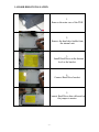
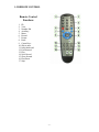
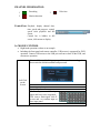
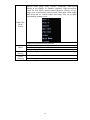
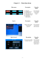
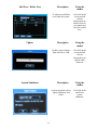
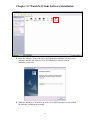
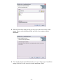
1
High Performance
Digital Video Recorder
With Linux OS
The default user name is : admin
The default password is : 1234
-------------------Manual
E Series 4CH Time Lapse
- 0-
- 1-
CAUTION
1. INSTALLATION ENVIRONMENT
1.1 Keep away from heat and extreme-temperature
1.2 Avoid direct sunlight
1.3 Keep away from humid areas
1.4 Place horizontally
1.5 Do not place anything on top of DVR
1.6 Do not block the fan
2. ACCESSORIES
*Refer to the particular packing list*
2.1 One power cord
2.2 One CAT5e network patch cable (Not a crossover cable)
2.3 One user manual
2.4 One installation CD
2.5 One ownership registration card
2.6 One remote control
2.7 Two AAA batteries
- 2-
Chapter 1 - Table of Key Functions
1.1FRONT PANEL
•
Note: Clockwise outer jog shuttle stands for right and anticlockwise outer
jog shuttle stands for left. Clockwise inner jog shuttle stands for down and
anticlockwise inner jog shuttle stands for up.
1.2 TABLE OF KEY FUNCTIONS
Order
1
Key name
Power switch
and indication
light
2
Recording light
3
Plastic Cover
CD-RW / DVDRW
4
6
Logo
POWER
LED
t u
Up & Down
Arrows
pq
IR Remote
8
Cancel
9
Enter
Power switch - Power off by pressing the key 4
seconds.
If the LED light is Green, it means the recording
is on
Dust-proof Cover
Used to Back- up records
Left & Right
Arrows
7
Function
L & R On screen Cursor Control; shifting level 1
and level 2 menus; Left and Right Camera Pan
control.
Up and Down Onscreen Cursor Control; change
setup; change number; Camera Tilt control.
Used to receive the remote signal.
EXIT
ENTER
Cancels cursor selection.
During playback, restore to real-time monitor.
Enter Cursor Selection.
- 3-
10
Function Key
AUX
Enter main menu.
In the Full Screen Mode:
Press the key to display the menu of the Camera
PTZ.
When setting Motion Detection fields, Fn1
Enables Cursor field selection.
During playback, display the playback status bar
11
Indication light
12
Jog shuttle
13
14
Record
Switch View
Mode
15
Play last section
17
Slow play
18
Play/stop
19
Fast Forward
Play next
section
20
21
USB
REC
VIEW
During playback work with number key to realize
PIP for the playback and real-time monitor.
Indication light
Direction control: outer Ring for Left and Right
direction, inner Ring for up and down; When in
playback, outer circle can control reve rse and
multi-speed play.
Start/stop recording, use with arrow keys
Select for Multi-Screen; During playback, shift
between Playback and Real time display.
9
Play the previous recording file.
?
8
3 levels of slow play speed adjustments: (15f/S 5f/S & frame by frame)
Play/stop
When in real time mode, press to enter record
search menu
3 levels of fast play speed - X2 - X4 - X8.
:
Play the next recording file after the current file.
„/;
Used for external storage such as memory stick or
Hard drive
Or for USB mouse control (additional USB on
back as well)
- 4-
1.3 BACK PANEL
•
Back Panel may be different according to the model
•
•
•
Power control: power on/off, power outlet, power fan
Main functions: RS-485, RS-232, VGA, USB, 1394 port, RJ-45
Audio and video input and output: audio output, audio input, video output,
video input
Note: Use crossover cable to connect DVR directly with computer.
- 5-
1.4 HARD DISK INSTALLATION
1.
Remove the outer case of the DVR
2.
Remove the hard drive holder from
the internal unit
3.
Install Hard Drive on the bottom
level or the bracket.
4.
Connect Hard Drive bracket.
5.
Connect Hard Drive data cable and set
the jumper to master.
- 6-
6.
Connect Hard Drive
power cable
7.
Close the cover and install the screws
- 7-
1.5 REMOTE CONTROL
Remote Control
Functions
1. ID
2. View
3. Number Pad
4. Auxiliary
5. Menu
6. Record
7. Escape
8. Enter
9. Cursor Keys
10. Skip to next
11. Jump-backward
12. Fast-forward
13. Play
14. Next Record
15. Slow- forward
16. Play/Pause
17. Stop
- 8-
CHANNEL INFORMATION:
1
Recording
2
Motion detection
3
Video loss
Control bar Playback, display channel date,
time, speed and progress, control
speed circle playback and full
screen.
Control bar is hidden in full
screen, click mouse to display.
1.6 MOUSE CONTROL
•
•
Right hand operation is taken as an example
Including the front panel and remote controller, USB mouse is supported for DVR
operation. Connect USB mouse to the USB port on front or back of the DVR, and
start mouse operation.
‘User and Password’ dialog pops up if the user has not logged in,
please enter the default username and password.
Left Click
on the
Screen
User name: admin Password: 1234
Execute operation
Pop up drop-down frame
Numeric input or Alfa input
(upper and lower case) supported;
Click icon to finish input: click X
to reset and v to confirm input or
close input panel
- 9-
Shortcut menu popup under real-time monitoring: Multi-screen
(related to the number of channels supported: single-screen/fourscreen for 4CH DVR), pan-tilt control (protocol correctly set up),
image color, record search, manual record, alarm input, alarm output,
main menu and etc. Pan-tilt control and image color set up under
corresponding channel screen.
Right Click
on the
Screen
Wheel
Cursor
Moving
Cursor
Dragging
Right click to cancel the setup and exit.
Increase and decrease numerical value
Switch between options in combo box
Page-up and page-down
Cursor moving
Motion detection area selection
Area covering selection
- 10 -
Chapter 2
4 Channel Menu
Operations
- 11 -
Chapter 2 – Menu Operations
Main menu
Description
v
v
v
v
v
v
Search
SEARCH
Left click on the
INFORMATION
screen and then
DVR SET UP
select main
ADVANCE SET UP
menu.
VIDEO BACK UP
SYSYTEM
SHUTDOWN
Description
Quick Search
- 12 -
Using the
mouse
Using the
mouse
Realize quick search,
list search and
playback.
Left click on the
screen and left
click on search.
Description
Using the
mouse
Exact search according
to channel and time.
Left click on the
screen and left
click on search
and left click on
quick search.
List Search
Hard Disk ( to setup hard disk)
Bit Rate
- 13 -
Description
Using the
Mouse
Search according to
recording type; all,
regular alarm, md
(motion detection),
result is displayed in
list. R – regular, A –
alarm, M – motion
detection.
Left click on the
screen and left
click on search
and left click on
list search.
Description
Using the
mouse
IDE connection state, each
or all HDD capacity, free
space, recording start and
end time.
Left click on the
screen and left
click on
information and
left click on
hard disk.
Description
Using the
mouse
Display Bit rate (Kb/s), of
every channel.
Left click on the
screen and left
click on
information and
left click on bit
rate.
Log
Description
Using the
mouse
Display system logs of
important events.
Left click on the
screen and left
click on
information and
left click on log.
Description
Using the
mouse
Display hardware
characteristic, software
version and build date.
Left click on the
screen and left
click on
information and
left click on
version.
Description
Using the
mouse
Version
DVR Set Up
v
v
v
v
v
v
v
v
v
v
- 14 -
SYSTEM
COMPRESSION
SCHEDULE
MOTION
DETECTION
ALARM
PTZ
MANUAL
RECORD
NETWORK
DISPLAY
DEFAULT
Left click on the
screen and left
click on DVR
setup.
System
Compression
Schedule
- 15 -
Description
Using
the mouse
Basic parameters such as
system time, recording,
mode, serial number and
video mode.
Left click on the
screen and left
click on DVR
set up and left
click on system.
Description
Using the
mouse
Setting of parameters such
as video encoding mode,
frame rate, quality.
Left click on the
screen and left
click on DVR
set up and left
click on
compression.
Description
Using the
mouse
Time slots for scheduled
operation ( record, receive
exterior alarm, open
motion detection each day.
Two time slots are
available for each type.
Left click on the
screen and left
click on DVR
set up and left
click on
schedule.
Motion Detection
Alarm
PTZ
- 16 -
Description
Using the
mouse
Setting parameters such as
motion detection level,
area, and handle alarm
output and start recording.
Left click on the
screen and left
click on DVR
set up and left
click on com
port.
Description
Using the
mouse
Setting of exterior alarm
output and responding
record parameter. NO:
Normal Open. NC: Normal
Close.
Left click on the
screen and left
click on DVR
set up and left
click on
network.
Description
Using the
mouse
Configure PTZ cameras:
protocol, communication
parameters, and
communication address.
Left click on the
screen and left
click on DVR
set up and left
click on PTZ.
Manual Record
Network
Description
Using the
mouse
Setting of recording
Left click on the
screen and left
click on DVR
set up and left
click
on manual
record.
Description
Using the
mouse
Set up network parameters:
IP address, subnet mask,
default gateway, TCP/IP
ports.
Left click on the
screen and left
click on DVR
set up and left
click on
network.
Note: For more
information on DDNS,
please visit
http://dynamicipview.com
Note: If the DVR is
directly connected to the
modem / DSL, click on
enable PPPoE and enter the
user name and the
password and click save.
Display
- 17 -
Description
Using the
mouse
Setting of menu output
and monitoring parameters.
Left click on the
screen and left
click on DVR
set up and left
click on display.
Default
Video Backup
Description
Using the
mouse
Restore system parameters
to the factory default.
Left click on the
screen and left
click on DVR
set up and left
click on default.
Description
Using the
mouse
Left click on the
screen and left
click on video
backup.
Advanced Setup
Description
v HDD MANAGER
v USER ADMIN
v UPDATE
- 18 -
Using the
mouse
Left click on the
screen and left
click on
advanced set
up.
HDD Manager
Description
Setting hard disk such as
write mode, length of video
and format HDD.
User Admin
Description
v MODIFY
PASSWORD
v ADD/DELETE
USER.
Modify Password
Description
To modify user password.
- 19 -
Using the
mouse
Left click on the
screen and left
click on
advanced set up
and left click on
HDD manager.
Using the
mouse
Left click on the
screen and left
click on
advanced setup
and left click on
user admin.
Using the
mouse
Left click on the
screen and left
click on
advanced set up
and left click on
user admin and
left click on
modify
password.
Add User / Delete User
Description
To add users and delete
users from the system.
Update
Description
Update system software
from network or USB.
System Shutdown
Description
System operation such as
logout, shutdown, and
restart.
- 20 -
Using the
mouse
Left click on the
screen and left
click on
advanced set up
and left click on
user admin and
left click on add
user.
Using the
mouse
Left click on the
screen and left
click on
advanced set up
and left click
alarm out.
Using the
mouse
Left click on the
and left on
system
shutdown.
Chapter 3 DDNS Setup
You must register the name (code) with
dynamicipview.com and enter that registration code
to use as your identification on the Dynamic IP server
for DVR.
An IP address is the address of the computer on the internet. Most providers assign a new IP address
every time a connection is made to the internet. The result is that when an IP address changes the
connection to the internet is lost. The IP address of both server and the client computer must be linked
to keep the connection between them. Dynamic IP servers are designed to act as a third party in order
to keep a static connection.
DVR Setup
1. Go to web site http://www.dynamicipview.com , complete the on-line
registration form.
2. Write down the information after you successfully submit the registration
form:
Server Host, User Name, Directory, Password.
3. Log on to DVR, select "Main Menu", select "DVR SET UP", select "NETWORK".
- 21 -
4. On "NETWORK" setting menu, enter DVR's IP, subnet mask, gateway. Choose
the desired service port and http port. If you are not sure which IP address and
port should be used, please contact your network administrator or call our
technical support for detail information.
5. Select "DDNS/PPPOE" setting menu.
• DDNS ENABLE: checked
• SERVER IP = 66.163.26.245
• SERVER HOST = (enter the host name that you have registered on-line into this
box)
• PORT = 7070
• PPPOE: unchecked
Click "SAVE" and exit. It might prompt to restart your DVR system depending on
different version of firmware and hardware.
6. Select "FTP" setting menu.
• UPLOAD ENABLE: checked
• FTP IP = 66.163.26.245
• FTP PORT = 21
• DIRECTORY = (enter the directory that you have registered on-line into this
box)
• USERNAME and PASSWORD = (enter the user name and password that you
have registered on-line into these boxes)
Click "SAVE" and exit. It might prompt to restart your DVR system depending on
different version of firmware and hardware.
- 22 -
Chapter 3.1 WatchNet Client Software Installation
v Insert the software CD in to the CD or DVD-Rom drive and then left click on my
computer and then left click on CD or DVD-Rom drive and left click on
WatchNet_Client 6.44.
v When the WatchNet_Client6.44 icon in the CD or DVD-Rom drive is left clicked,
the software would prepare to install.
- 23 -
v To continue with the installation click next.
v Click next to install to the folder, or click change to install to a different folder.
- 24 -
v When left clicked on change on the previous screen, the screen above would
appear. Browse to the destination folder and click ok to continue with the
installation.
v Click install to begin the installation and to review or change any of installation
setting click back or click cancel to exit the installation wizard.
- 25 -
v During the installation in may take several minutes, according to the system
speed.
v Now the DVRNet View has successfully installed, left click on finish to exit the
wizard.
v Left click on DVRNet View icon in the desktop to open the DVRNet View.
- 26 -
v If the DVRNet View icon doesn’t appear in the desk top, left click on the start and
then left click on program and then left click on DVRNet View and left click on
DVRNet View again to open the DVRNet View.
v When the DVRNet View icon is left clicked, the DVRNet View screen would
appear.
- 27 -
Chapter 3.2 First Use
v The following screen will appear. Click on
.
v For access through high speed internet or network select “Network Login” and
click “OK”.
- 28 -
v Click on “Add” to add a new site to connect to.
v Enter a name for the remote site you wish to connect to. Then enter the IP address
of the DVR followed by the TCP port that is set for the DVR to connect to. This
port is set in the network section of the DVR.
v Select the site and then click on “Login”
- 29 -
v Enter the username and password to log into the DVR.
The default user name is: admin
The default password is: 1234
v To search through and playback recorded video, click on “DVR search” and then
enter the date, time and camera number you want to search. Then click on
“SEARCH” and the fo llowing window will appear.
DVR Search :
v Enter recording time, channel number and type (Normal, Alarm/Sensor,
Motion) and the results will appear below. The screen displays 15 records at a
time starting from the entered search time onwards. Click on “Page Up” and
“Page Down” button to get to the next next/previous group of 15 records. Once
the required record is located, double click on it and system will play the
record. This video can be played in full screen mode. You can also
- 30 -
simultaneously download records to your computer. By default the records are
saved in the “Download” folder in the C drive (C:\ Download).
v To download the video clip to your computer, select the clip and then click on
download. You can select multiple clips and the software will download them
all simultaneously. After clicking on download the following screen will
appear:
v You must enter some text for the file name and the rest of the name will be
auto generated using the following scheme.
v File name of the download consists of your entered text followed by year (e.g.
2006), month (e.g. 05), date (e.g. 29), hour (e.g. 16), min (e.g. 48), sec (e.g.
41) and camera number (e.g. [1]).
v Once the file name is entered click on save and the file will be downloaded.
The following screen displays the progress of the download.
v Click on the “DVR SETUP” button and a window will appear with 6 options,
System, Schedule, Image, Alarm, Motion setup and Video parameters.
v Note: If a menu item is greyed out, it can’t be changed and can only be
modified directly from the DVR.
General:
- 31 -
v When Disk Fill: This option allows you to prevent the DVR from automatically
overwriting the hard drive when it is full.
v PTZ Control: Use these options to enter the control information for the PTZ
camera.
- 32 -
Schedule :
v Week: Use to define unique recording schedules for each day or select “All”
to apply the same schedule for everyday.
v Normal 1 / 2: Use this setting to record all the time. There can up to 2 start
and end times for this recording method. The time entered from the start to
end duration will have continues recording. And as mentioned in the note
above, If you want to record on normal for 24 hours then set TIME1 as 00:00
to 24:00 in ON status and TIME2 as OFF.
v Motion Recording 1 / 2: Use this setting to record only if there is motion
detected by the camera. There can up to 2 start and end times for this
recording method. The time entered from the start to end duration will have
motion only recording. And as mentioned in the note above, If you want to
record on motion only for 24 hours then set TIME1 as 00:00 to 24:00 in ON
status and TIME2 as OFF.
- 33 -
Image :
v Camera : Can be selected to modify settings for individual camera or select
“ALL” to apply changes to the recording schedule for all cameras.
v Style: There are 2 recording formats, VBR (Variable Bit Rate) and CBR
(Constant Bit Rate). The CBR by default records at the maximum possible
frame rate but it can be manually lowered to 1 to 20 frames per seconds as
shown above.
v Quality: Use this option to select the quality of the video. The higher quality
takes up more space on the hard drive. There are 6 qualities 128Kb/S,
256Kb/S, 384Kb/S, 512Kb/S, 768 Kb/S, and 1 Mb/S.
- 34 -
v Video loss output: Use this to trigger a relay in case of video loss.
v Network Protocol: Use this option to select the network settings.
Alarm :
v Alarm Port: Can be selected to modify response to an individual sensor input
or select “ALL” to apply changes to the action due to all input sensor.
v Record camera: For each sensor input signal we can force a camera to start
recording.
v Output Port : For each sensor input signal we can trigger a relay.
Motion Setup :
- 35 -
v Detection Region: The squares that are highlighted by the blue squares are
the region, in which the camera will detect motion.
v Full Screen: Select the full screen to enlarge the video from the camera to the
full screen allowing you to easily select the detection region. To exit the full
screen mode right click any where on the screen.
v Post Rec: This is the setting for the number of seconds of recording after
motion is detected.
v Sensitivity: This is to adjust the sensitivity of the motion detected in the
detection region. The options are low, normal and high.
Video Parameter :
- 36 -
v This window can be used to set various attributes like the video Hue, Contrast,
Brightness and Saturation, the OSD (On Screen Display) settings and audio
options.
v Click on DVR Config and the following options menu will appear. The details
of the function are described below.
- 37 -
v Change Language : Use this option to change the default language.
v Use this option to add, delete and modify users. Also you can modify access
level to the DVR system for each user.
v There are 3 access levels.
v Guest: Only has access to view the cameras and modify personal details. This
access level can’t change anything on the system and also can not search.
v User: This access level can not change system preferences or other user’s
details, other wise has access to other things including search.
v administrator: Has complete access.
- 38 -
Camera Name :
v Use this option to change the display names for the cameras. The name will
initially be greyed out so the user must click on the “Modify” button to be
able to change the names. Click on “Save” after.
Request Control :
v The web client software allows multiple users to view the video but if the user
wants control of the system to access the PTZ or change information this
option can be used. If an existing user already has control of the system, when
a new user requests for control, the user will be asked for permission to
transfer control to the new user. If the users accessing the system have the
same access level the control is assigned to the first person that requests for it
but if a user with higher access level is present the control is automatically
transferred to the user with higher access. If only one user is logged in or the
user already has control the box is greyed out.
- 39 -
v This is the prompt the user with control will receive if another user requests
for the control. Click on OK to transfer the control and Cancel to keep it (not
transfer control to the other user)
Current Settings :
v Use this to check system information. Also from this window the user can
enable or disable the audio recording feature, select video transmission speed
(real time for live video and extract frame for less transmission). If the user
selects Auto Recycle Monitor the system will sequentially show each camera
according to the time interval selected by the user.
DVR Upgrade :
- 40 -
v An Administrator can upgrade the software installed on the DVR remotely
using this window. To upgrade the software click on open to browse the file,
then click on the appropriate button below. After the upgrade the DVR will
automatically restart.
View Log :
v Use this option to view the log saved on the DVR.
- 41 -
Matrix Control :
- 42 -
Chapter 3.3 To Uninstall DVRNet View
v Left click on Start and left click on programs and left click on DVRNet View
and left click on DVRNet View again and left click on Uninstall DVRNet
View.
v To continue with the uninstalling click yes.
v When yes left clicked on the above screen the windows would prepare to
remove the DVRNet View.
v It may take several minutes to remove the DVRNet View, according the
system speed.
- 43 -
Chapter 4 Features and Specifications
4.1 SPECIFICATIONS FOR DVR
Parameter
4CH
8CH
16CH
Processor
High performance industry level embedded microprocessor
Operation Linux Embedded operating system ( Linux )
System
System
Pentaplex operation: Multi-channel viewing, recording,
Resources
playback, set-up and network operation simultaneously
Interface
Friendly GUI (graphic user interface)
Input Devices
USB mouse, front panel, remote control or network simulator
Input
Built-In Alpha numeric keyboard
Shortcut
Copy/paste, USB mouse right-key shortcut menu, USB mouse
screen switch function
Video
MPEG-4/H.264
Compression
Audio
PCM
Compression
Video Input
4/8/16CH composite video input: (NTSC/PAL) BNC (1.0VP- P,
75O)
Video Output
2 BNC (1.0VP-P 75 ohm) composite video output, 1 VGA
output
Switch between BNC and VGA output
Video Standard NTSC (525 line, 60f/s), PAL (625 line, 50f/s)
Recording
Real-time recording: NTSC 1f/s to 30f/s per channel and PAL
Speed
1f/s to 25f/s per channel
Display
1/4 windows
1/4/9 windows
1/4/9/16 windows
Touring
Supported
Resolution
Real-time monitor: D1 704×576/704×480
(NTSC/PAL)
Record backup: CIF 52×288/ 352×240
Motion
192 (16×12) grid area configurable; multi- level detection
Detection
sensitivities
Image Quality
6 level image control selectable per channel
Area Masking
Random size selection for area masking protection
Image
Channel information, time information and protected area
Information
covering information
TV Adjust
Auto-adjustment for anemographic images; luminance and
contrast configurable
Screen Lock
Specific display screen lockable (Blue screen covered for
unauthorized users) to ensure data security
Channel
Channel name, recording status, screen lock status, video loss
Information
status, and motion detection status shown on the bottom left of
display screen
Color
Hue, luminance, contrast, saturation and signal gain configurable
Configuration
for each channel
- 44 -
Audio Input
Audio Output
Hard Disk
Hard Disk
Consumption
Hard Disk
Management
Recording
Mode
Recording
Duration
Overwrite/Stop
Mode
Record Search
Playback
Multi-switching
Mode
Multi-channel
Playback
Display Zoom
Selective
Enlargement
Backup
Features
Network
Control
Motion
Detection
Video Loss
External Alarm
4/8/16CH audio input 200-1000mv 10KO
1CH audio output 200-3000mv 5KO(RCA)
Supports up to 8 high capacity Hard Drives (6 with CDRW/DVD-RW)
Audio PCM 28.8Mbyte/Hour ADPCM 14.4Mbyte/Hour
Video 56-900Mbyte/Hour
Hibernating function for non-working Hard Drives reduces
power waste and extends life of Hard Drives
Manual, motion detection, schedule and alarm recording
1 to 120 minute file record duration configurable (Default 60
minutes)
Overwrite mode or stop mode selectable when hard disk is full
Search record by time, type and channel
Multi- level fast- forward, multi- level reverse, single frame
playback and scroll
Switch between recorded files
Switch between channels recorded at the same time
Play recorded files continuously (Auto-play record of the same
channel one file after another)
1 channel, 2 channel or Multi-channel playback for specific
mode
Split screen/adaptive screen/full screen for multi-channel
playback
Zoom in feature under full screen mode
Hard Drive backup
External USB storage devices (USB flash memory, Removable
Hard Drive, USB CD-RW).
IDE CD-RW, IDE DVD-RW
Network download and backup
Real-time monitoring
DVR configuration through client and web browser
DVR update through client and web browser
Check video loss and alarm information
Pan-tilt control
Record download and playback
Multi-DVR using Central Management Software
Duplex transparent serial port
Network alarm input and output
Voice dialog
Multi-screen preview
192 (16X12) configurable detection areas; multi- level sensitivity
adjustment recording and dialog box popup, relay triggers
message notification
Relay trigger and on screen message notification
Sensor recording, Relay trigger and on screen message
notification
- 45 -
Manual Alarm
Control
Alarm Input
Alarm Output
Alarm Relay
USB Port
Network
Interface
RS485
RS232
Hard Disk
Information
Bit Rate Stat.
System Log
System Version
Online User
User
Management
Password
Protection
Update
Login
Logout
Shutdown
Power Supply
Power
Consumption
Working
Temperature
Working
Humidity
Working
Atmosphere
Size
Weight
Installation
Mode
Enable and disable sensor inputs
Control output relays
16 channel grounding alarm input
6 channel relay output (1 controllable +12V output)
30VDC 2A, 125VAC 1A
Connect with external USB devices
RJ45 10M/100M adaptive Ethernet port
Pan-tilt control interface, multiple protocols supported
Common serial port, keyboard interface and transparent serial
port
IDE interface status, Hard Drive information, working Hard
Drive number
Bit rate statistic of each channel; bit rate waveform display
1024 items system log; search log by time and type
Recording channel number, alarm input & output channel
number, system version and release date
Online user display with lock out function
Multi- level user management; 48 configurable functions
Supports adding and modifying users and groups (no limitation)
Account lock: 5 password input attempt limitation. Lock out for
30 minutes
Web browser, client and specific update tool
USB flash memory update
Login by user name and password to ensure security
Logout, shutdown and restart selectable
Shutdown power configurable
220V+25% 50+2% Hz / 110V 60Hz
40W
0C -+ 55C
10% - 90%
86kpa - 106kpa
2U standard size; 440mm (width) X 460mm (depth) X 89mm
height
7.5 KG
Desk top or 19” rack mount
- 46 -
4.2 FEATURES
1 Analog CCTV monitor output, 1 spot monitor output and 1
VGA monitor output
1/4/9/16 window monitoring
Viewing
Options
Display of real-time bit rate and hard disk consumption
Information of recording, motion detection, video loss, screen
lock, view log file etc
Video Compression: MPEG-4/H.264
4/8/16CH video compression and real- time hardware
Compression
Mode
compression for each channel
Real-time synchronization for audio and video
Supports up to 8 large capacity Hard Drives
Storage
Overwrite mode and stop mode selectable when hard disk is full
Special storage format for data security
IDE port (hard disk and IDE CD-RW) backup and USB port
(USB flash memory, USB removable Hard disk and USB CDBackup
RW) backup
Download and backup through network
Multi-task operation: real-time recording, single channel
playback, remote monitoring, records search and etc.
Multiple recording modes: manual recording, schedule recording,
alarm recording, motion detection recording (pre-recording for
alarm recording and motion detection recording).
Recording and Record playback through network
Playback
Fast classified record research function.
Multiple playback mode: fast- forward, slow- forward, single
frame and backward.
Display of accurate recording time.
Selective enlargement under full screen mode
Remote monitoring
Pan-tilt control
Record search and playback
DVR parameter configuration and software update
Network
Operation
Remote alarm management and system log search
Embedded TCP/IP protocol enables Web browser control
Multi- level user management; power configurable for different
user and group
4/8/16 channel grounding alarm input; video loss alarm and
motion detection alarm supported; panel alarm includes smoke
detector, IR detector etc.
Alarm Relay
Multi-channel relay output, enables alarm relay and onsite
lighting control
Protective circuit for both alarm input and alarm output
Special interface for alarm input and pan-tilt control
Communication One RS232 port used for keyboard expansion, normal serial port,
Interface
matrix control etc.
One RJ-45 port for network control
Support pan-tilt decoder using RS485 port
Pan-tilt Control
Multiple decoding protocols expandable for pan-tilt and speed
- 47 -
Smart HDD
Manager
Intelligent
Operation
dome control
Alarm outputs for corrupt and unusable Hard Drives
Allows non-working hard disks to hibernate to reduce power
consumption and extend lifetime.
Full mouse control, built in keyboard & copy, paste, & function.
- 48 -
Chapter 5 Operational manual before installation
5.1 PRIMARY CHECK
•
When you receive the DVR, the first thing you must do is to check if there is any
obvious damage to the appearance. The protective materials used for the package
of the DVR can handle most accidental clashes during transportation.
5.1.1 OPENING YOUR DVR
•
Open the box and check all contents. Check the items against the list on the
warranty card. After check is complete remove the protective cover of the DVR.
5.1.2 FUNCTIONS AND CONNECTIONS
•
•
Various key functions on the front panel and various interfaces on the rear panel
are introduced in detail in this instruction manual.
Please check the model against your purchase carefully. The tag on the rear panel
is very important for after-sales service. Do not destroy or discard it. To provide
warranty, the product’s serial number is required.
5.2 INTERNAL FUNCTIONS
5.2.1 INSTALLING HARD DISK DRIVES
•
Hard Drives must be jumped as Master or Slave for each IDE slot
5.2.2 SELLECTING HARD DISKS
•
7200 rpm or higher Hard Disk Drives have been tested to work best with our
DVRs.
5.2.3 SELECTING HARD DRIVE SIZE
1.
The DVR can handle
40 Gig to 500 Gig Hard Drives, (Stability tested 120 Gig to 250 Gig
in the lab)
2. Calculating recording time of Hard Drive
The computing formula of total Hard Drive size is:
The total size (M) = channel numbers X recording hours X Hard Drive used per
- 49 -
•
hour (M/h)
So we can get the computing formula of recording hours:
Recording hours= the total size M
Hard Drive used per hour (M/h)
Because the DVR adopts MPEG4/H.264 compression technology, this will produce a
considerable dynamic range when compressing data. So when you calculate the
total Hard Drive size, you should estimate the average Hard Drive size per hour
per channel.
Example: For a 4ch DVR, the average size of Hard Drive used per hour per
channel is 200M/h. Now if you hope the DVR can record for 30 days with 24
hours one day, the total size of Hard Drive needed is: 4 channels * 30 days * 24
hours * 200 M/h = 576G. So you need install five 120G Hard Drive s or four
160G Hard Drives.
5.2.4 HARD DRIVE INSTALLATION (SEE DIAGRAM IN CHAPTER 3)
•
•
IDE cables, fastening screws and a Hard Drive shelf are already provided in the
accessories to simplify your installation.
Pay special attention to Hard Drive jumper configuration: If only one Hard Drive
is connected to an IDE port, the jumper must be to MASTER. If two Hard Drives
are connected to one IDE port, one jumper must set as MASTER and the other as
a SLAVE. Do not set Hard Drive as CS Enable or Cap Limit.
5.2.5 ABOUT CD/DVD BURNERS
•
DVR supports IDE port and USB port Burners. If you use an IDE port to connect
CD or DVD burner, you must set the jumper as MASTER. Use our company’s
already tested brands. You can consult the technical support or visit our website
for details. After Hard Drive and burner installation, double check that the IDE
cables and power cord is secured before mounting the outer cover.
5.2.6 CONNECTION OF EXTERIOR POWER SUPPLY
•
•
Switch the clasp near the power socket to the correct position according to the
input voltage. (110V or 220V operation)
It is recommended to use an uninterruptible power supply (UPS) to protect the
DVR from power surges and failures.
•
5.2.7 INSTALL DVR IN A SERVER CABINET
•
The size of DVR is 2Ustandard industrial case 441mm (Wide) x430mm (Deep)
x89mm (High)
Put the cabinet in a place with circulated air. Avoid extreme heat, humid and
heave dusty conditions. You should clean inlet opening, cooling fan etc. with a
- 50 -
soft dry brush.
5.3 CONNECTING VIDEO/AUDIO INPUT/OUTPUT
5.3.1 VIDEO INPUT CONNECTIONS
•
•
•
•
•
•
•
The video input interface is BNC. The request of video input is NTSC/PAL
BNC 1.0VP- P 75O.
The video signal should meet terms with the national standards. High SNR, low
distortion, low interference, natural color and suitable brightness are needed for
the video signal.
To ensure a stable and reliable camera signal, the cameras should be installed
properly. Under backlighting, low illumination surroundings that are not
suggested, the user should use a backlight compensation camera or low
illumination camera.
The power supply of the camera should be grounded with the power supply of the
DVR to ensure the normal operation of the camera.
Use a high quality, good-shielded cable and choose a suitable BNC model
according to the transmission distance. For longer distance, you should use
twisted pair, add video compensation devices or use optical fiber transmission to
ensure video quality.
Keep the video signal away from strong electromagnetic interference, especially
high tension current.
BNC connections on both ends should be well connected. Avoid dry joint, lap
welding and rust.
5.3.2 AUDIO INPUT CONNECTIONS
•
•
4, 8 channel and 16 channel DVRs use an RCA audio connections. Due to high
impedance of audio input, amplified microphones must be used.
Audio transmission is similar to video transmission. Try to avoid interference, dry
joint, loose contact and high tension current.
5.3.3 VIDEO OUTPUT CONECTIONS
•
•
•
Video output includes 2 BNC (1.0VP- P, 75O ) outputs and a VGA output.
We recommend you use a CCTV monitor as video output device.
The CCTV monitor has the following advantages:
- 51 -
•
•
1. Can adapt long-time monitoring. Ordinary residential devices are easy to
age, damage and even burn under long-time operation.
2. Has higher definition and color recover ability
3. Better stability and anti- interference ability, adapt to various complicated
surrounding.
When a PC monitor is used, the following points should be considered
1. PC monitor cannot be powered on for long period of time.
2. Regular demagnetization benefits the monitor to work in normal state.
3. Keep away from strong electromagnetic interference devices.
Using TV as video output devic e
1. Reduce the hours of use to prevent image burning
2. Control interference from the power supply and other devices.
3. Short circuit problems of low quality TVs may damage other devices.
5.3.4 AUDIO OUTPUT CONNECTIONS
•
•
The audio output parameter of the DVR is 2000mvp-p 1KO (BNC). It can
connect directly with low impedance earphone, active sound box or amplifierdrive audio output device.
If the sound box and the pick-up cannot be separated spatially, it will most likely
cause squeaking. At this time, you can adopt the following measures:
1. Use better sound pick-up with better directing property.
2. Reduce the volume of the sound box to the value under which squeaking
discontinues.
3. Using more sound-absorbing materials that can reduce voice echo and
improve acoustics environment.
4. Adjust the layout to reduce squeaking.
5.4 CONNECTION OF ALARM INPUT AND OUTPUT DEVICES
•
•
•
•
Before connection, please pay attention to the following points:
1. Alarm input
First confirm if the alarm input is a grounding alarm input and not a voltage alarm
input. A grounding signal is needed for alarm input.
2. Alarm output
The alarm output port should not be directly connected to a high power load. To
avoid a heavy current that will destroy the relay, use a co contactor between the
alarm output port and the load.
3. How to connect PTZ decoder
Ensure the decoder has the same grounding as the DVR; otherwise common mode
voltage may fail to control the PTZ. Shielded twisted wire is recommended and
- 52 -
•
•
•
•
•
•
the shielded layer is used to connect to the ground ing.
Avoid high voltage. Ensure proper wiring and protective measures
For long signal wires, 120O should be parallel connected between A, B lines on
the far end to reduce reflection and guarantee the signal quality.
“485 A, B” of DVR cannot parallel connect with “485 port” of other device.
The voltage between of A, B lines of the decoder should be less than 5v.
Provide the power to alarm device with a current less than 1A.
Poor grounding of the front-end devices may cause damage to chips.
Descriptions about alarm input and output
1. ALARM (1…16) are 16 channels grounding alarm input.
2. In OUT row, 1-NO C, 2-NO C, 3-NO C and 4-NO C are 4
3. Normal open relay outputs. 6-NO C NC is a NO/NC relay
output.
4. “12V”: Need peripheral equipment provide +12 power with 1
A current.
5. AB: used to connect some control devices such as pan/tilt
decoder.
6. If you connect many pan-tilt decoders, you should parallel
connect
7. 120O between A, B lines.
8. “
•
•
•
•
•
•
•
•
•
•
”ground.
16 channel grounding alarm inputs. (Both Normal open and Normal close type)
Short connect between COM end and GND end of the alarm detector (the power
of the alarm detector must be provided by outside power).
Parallel connect the Ground of the DVR and the ground of the alarm detector.
Connect the NC port of the alarm sensor to the DVR alarm input (ALARM)
If you need to restore the touched-off alarm remotely, you have to supply the
controllable 12 V power of the DVR to the alarm detector, such as the smoke
detector.
Connect the ground of the outside power with the ground of DVR.
2 ways relay alarm output (normal open contacts). Should provide the power
supply to the alarm detector.
To avoid over loading, please read carefully about the related parameters of the
relay. (See below table)
The controllable +12v can provide the power for restorable smoke detector.
5.4.1 RELAYS’ PARAMETER OF THE ALARM OUTPUT END
•
The 25-pin RS485 port is realize pan-tilt- zoom control, enables the activation of
alarms. RS485 connection can control carious pan-tilt-zoom decoders, and the
specific type of the decoder can be selected in the setting in the menu. Switch out
pin number is marked on DB25 plug. The definition of the pin is as below. The
- 53 -
broken line the graph means it’s being connected inside.
•
1 14 2 15 3 16 4 17 connects to alarm input: ALARM1~ ALARM8
•
5 18-OUT1 6 19-OUT2 two linked open output
•
7 20-OUT3 are connected inside either is controllable +12V output
•
8 9 21 are +12V power output, able to be as the power supple for alarm sensors
•
Either pin 10 22 is the B line of RS485, either pin of 11 23 is the A line of RS485
•
12 13 24 25 are earth lines
5.5 SELECT AND CONFIGURE RECORDING MODE
•
The DVR can provide multiple recording modes. The user should configure the
recording mode due to actual needs. To get the best balance between the recording
time and Hard Drive space used, the user should pay attention to the following
points:
1. The recording period for motion detection or alarm cannot overlap within
the recording schedule.
2. Under poor illumination, the user should avoid using motion detection
recording. It is suggested to use a more stabilized alarm recording with
linked light control to assure the recording quality and rational use of the
Hard Drive.
3. The sensitivity of motion detection should be adjusted and tested
according to the environment to avoid to false reports or failure to report.
5.6. NETWORK CONNECTION
•
•
DVR provides a standard RJ45 port and embedded TCP/IP protocol to connect to
the LAN or Internet. During configuration of a LAN, please use a switch instead
of a HUB. This will guarantee enough bandwidth and avoid long distance wiring.
Please choose proper bandwidth access mode.
Ethernet cable should be made according to standard.
- 54 -