1
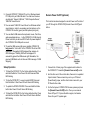
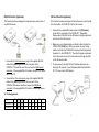
Introduction
CIP900-IP-TR
HDMI with USB
Over
IP Intranet
(Multi-cast Version)
Installation and User’s Manual
The CIP900-IP-TR system is a perfect solution to extend HDMI,
USB, and optional IR/RS-232/Remote-Power-ON-OFF over IP
network. It includes an CIP900-IP-T transmitter and an
CIP900-IP-R Receiver. The CIP900-IP-T transmitter connects with
PC or any device with HDMI source. The CIP900-IP-R receiver
connects to HDMI display, speaker, microphone, USB devices
(Keyboard/Mouse/Storage/…) and RS232 devices. It based on the
standard Ethernet IP network, all Gigabit or Fiber LAN switch HUB
can be used for inter-connection.
Package Includes:
(1) CIP900-IP-T Transmitter Unit
(1) CIP900-IP-R Receiver Unit
(1) HDMI-HDMI or HDMI-DVI cable
(2) 5V DC Power Supplies
(1) User’s Manual
Optional Accessories:
(1) 3.5m mini-stereo to DB9 Female RS232 control cable
(1) 3.5m mini-stereo to DB9 Male RS232 control cable
(1) 3.5m mini-stereo to 2-pins Remote Power on/off cable
(1) IR blaster cable
1
2
i-Tech Company LLC
TOLL FREE: (888) 483-2418 • EMAIL: [email protected]
• WEB: www.iTechLCD.com
Panel View
CIP900-IP-T Transmitter
Short press
Switch to Video or Graphic
mode
Long press
(*)Anti-Dither Mode
2 (Button 2)
Press and Hold at
Power ON until
Green LED blinking
3 Red LED
(System status)
4 Green LED
(Power/Link
status)
5 Remote Power
On/Off (optional)
No. Component
1 HDMI (or DVI-D)
Loop-out
Description
HDMI (or DVI-D) Loop-out for Local Monitor.
Short press
Long press
2 (Button 1)
Press and Hold at
Power ON until
Green and Red
LED blinking
3
6 Link ID
Get and Use EDID from
Loop-out monitor
Green Blinking/Red Off: System is starting up.
Green On/Red Blinking: Linking or waiting HDMI
input source.
Green On/Red On: Connection established.
Connects to PC motherboard for Remote Power
On/Off.
4 bit DIP switch for 16 ID settings. To make
Transmitter/Receiver as a pair or group, the
transmitter and receiver must be set with the same
Link ID.
Connects to Gigabit switch or directly to
CIP900-IP-R
Switch video to Remote or
Loop-out monitor.
7 Gigabit Ethernet
Output video to both
Remote and Loop-out
monitors.
8 RS-232 Control
(optional)
Provide Serial-over-IP function.
9 DC 5V In
System power input (DC 5V 2A)
Reset the unit to the
Factory default setting.
4
10 USB-to-PC
Connects this USB-B to PC to provide 2 functions:
1. USB audio device. (An USB audio device will be
detected when it is attached to PC in Windows OS)
2. Virtual 4-port USB Hub for remote USB devices.
11 HDMI IN
Connects to HDMI Source. For DVI source, you
may need a HDMI-to-DVI adapter cable.
12 IR Blaster
(optional)
Connects to external IR LED.
No.
1 Green LED
(Power/Link status)
2
Red LED
(System status)
Green Blinking/Red Off: System is starting up.
Green On/Red Blinking: Linking or waiting
HDMI input.
Green On/Red On: Connection established.
3
Link ID
4 bit DIP switch for 16 ID settings. To make
Transmitter/Receiver as a pair or group, the
transmitter and receiver must be set with the
same Link ID.
4
USB Host
For remote USB devices, such as USB
KB/Mouse, storage, audio, …
5
IR Rx (optional)
Remote Universal IR receiver.
6
Remote Power
On/Off (optional)
Button for Remote PC Power On/Off function.
Panel View
CIP900-IP-R Receiver
7
8
5
Description
Component
Mode button
Short press
Switch to Video or Graphic
mode
Long press
(*)Anti-Dither Mode
Press and Hold
at Power ON
until Green LED
blinking
Get and Use this Receiver’s
EDID as the system EDID
(update CIP900-IP-T EDID)
Short press
Link/Unlink
Long press
This CIP900-IP-R will get the
USB access right.
Link button
6
Press and Hold
at Power ON
until Green and
Red LED
blinking
9
10
DC 5V In
HDMI OUT
11 RS-232 Control
(optional)
Installation
Reset the unit to the Factory
default setting
System power input 5V 2A, or 4A when used
with 4 x USB devices.
1. Make sure the Link-ID of both CIP900-IP-T and CIP900-IP-R
are having the same setting. They make pair or group
according to this Link-ID setting.
Connects to HDMI display. For DVI display, you
may need a HDMI-to-DVI adapter cable.
2. Attach your HDMI display to the CIP900-IP-R HDMI-Out port.
Provides Serial-over-IP function.
3. Power on the CIP900-IP-R, an “AVExtender” logo will be
displayed. If not, then something wrong either on the
CIP900-IP-R or HDMI cable or HDMI display.
Microphone Input for the USB audio device.
(Please set the OS default audio device to the
12 Mic IN
USB PnP audio device that created by
CIP900-IP-T)
Stereo Audio output for the USB PnP audio
device. (Please set the OS default audio to the
13 Line OUT
USB PnP audio device that created by
CIP900-IP-T)
Connects to Gigabit switch or directly to
14 Gigabit Ethernet
CIP900-IP-T
(*)
Please follow the following procedures to install Multi-Cast
CIP900-IP-TR:
For some of ATI graphic card that with Dithering function
enabled, you may set to “Anti-Dither Mode” to achieve the
better Video quality.
4. You can connect multiple CIP900-IP-R and multiple
CIP900-IP-T units to your Gigabit Ethernet switch. Or you can
also use a CAT6 UTP cable (straight, EIA 568B) to directly
connect a CIP900-IP-T with a CIP900-IP-R as a pair
connection.
5. Attach your HDMI source (either PC or Blue-ray Disc) to the
CIP900-IP-T HDMI-In port and then power On the
CIP900-IP-T.
6. The first CIP900-IP-R that being detected by the CIP900-IP-T
will gain the USB access right.
7. If you are using PC as your HDMI source, you shall be able to
see your HDMI display EDID information on the PC graphic
card control panel. If not, then something wrong either on the
CIP900-IP-T or HDMI cable.
8. Output your HDMI (with audio) from your HDMI source and
check if they are correctly displayed on your HDMI display.
Please follow the following procedures to install Multi-Cast
CIP900-IP-TR for USB over IP:
7
8
9. Connects CIP900-IP-T USB-to-PC port to a Windows based
PC USB port by an USB-A-B cable. You shall see 3 devices
are detected: “Generic USB Hub”, “USB Composite Device”,
“USB PnP Sound Device”.
10. You can select “USB PnP Sound Device” as Windows default
sound device in order to use speaker and microphone on the
CIP900-IP-R Line-Out (green) and Microphone jack (pink).
Remote Power On/Off (optional)
This function has been designed to remote Power on/off control of
your PC through the CIP900-IP-R [Remote Power On/Off] push
button.
11. You can attach USB devices like keyboard, mouse, Pen Drive,
audio speak/microphone … to the CIP900-IP-R 4 USB-A ports.
Please note that you will need DC 5V with 4A power adapter if
all of CIP900-IP-R 4 USB ports are used.
12. To gain the USB access right among multiple CIP900-IP-R,
long press the “Link button” of the CIP900-IP-R until an OSD
message of “Requesting USB” displayed then release. An
OSD message of “Starting USB” will be displayed if it
successfully gained the USB access right. Meanwhile, the
previous USB Master unit will show an OSD message of “USB
Stopping”.
Setup Operation
1. To Reset the CIP900-IP-T to the Factory default setting: Press
and Hold the Button 1 then Power ON until Green and Red
LED blinking.
2. To Use the CIP900-IP-T Loop-out monitor EDID: Press and
Hold the Button 2 then Power ON until Green LED blinking.
3. To update the CIP900-IP-R EDID: Press and Hold the Mode
button then Power ON until Green LED blinking.
4. To Reset the CIP900-IP-R to the Factory default setting: Press
and Hold the Link button then Power ON until Green and Red
LED blinking.
9
1. Connects the 3.5 mm plug of the supplied control cable into
the CIP900-IP-T Transmitter [Remote Power on/off] socket.
2. And the other end of the control cable, there are 2 x separated
2-pins holders. Please connect any one to your PC board
[Power Reset] jumper, and the other holder connects to your
PC Reset button cable.
3. On the front panel of CIP900-IP-R Receiver, please just press
the [Remote Power On/Off] button. Then you can remote
Power Off your PC. If press the button again, it will remote
Power On your PC system again.
10
RS-232 Control (optional)
Infrared Control (optional)
This function has been designed to remote access and control of
any RS-232 device.
This function has been designed to transmit remote control signal
from the location of CIP900-IP-R to the AV sources.
1. Connects the supplied IR blaster cable to the [IR blaster]
socket at the rear panel of the CIP900-IP-T Transmitter.
Please check if the LED on the IR blaster is rightly positioned
in the front of the AV sources.
2. Make sure your infrared remote controller is able to align the
1. Connects the 3.5m mini-stereo plug of the supplied RS-232
cable to the [RS-232] socket at the rear panel of the
CIP900-IP-T Transmitter, and then connect the DB9 Female
connector of the supplied RS-232 cable to the [RS-232] output
port of your PC.
CIP900-IP-R [IR Rx] port. When you press any key on any
remote controller, the CIP900-IP-R receives the IR signal and
transmits it to the CIP900-IP-T. Then the IR signal is delivered
to the IR receiver of your AV sources device through the LED
on the IR blaster cable.
3. To work properly, the LED of the IR blaster cable must be
facing the IR receiver of your Windows Media Center Edition
PC, TV tuner card or DVD player.
2. Connects the 3.5m mini-stereo plug of the supplied RS-232
cable to the [RS-232] socket at the rear panel of the
CIP900-IP-R Receiver, and then connect the DB9 Male
connector of the supplied RS-232 cable to the RS-232 device.
Pin Assignments
Signal
CIP900-IP-R
CIP900-IP-T
-NC- TxD RxD -NC- -NC- -NC- -NC- -NC- -NC5
5
3
2
2
3
7
8
11
8
7
4
6
6
4
1
1
9
9
12