1
P42VCA20UH
FUJITSU
GENERAL
Copy Prohibited
Proprietary
CONTENTS
IMPORTANT INFORMATION . . . . . . . . . . . . . . . . . . . . . . . . . . . . . . . . . 2
SPECIFICATIONS . . . . . . . . . . . . . . . . . . . . . . . . . . . . . . . . . . . . . . . . . . 4
SETTING SIGNALS . . . . . . . . . . . . . . . . . . . . . . . . . . . . . . . . . . . . . . . . 5
CONNECTION . . . . . . . . . . . . . . . . . . . . . . . . . . . . . . . . . . . . . . . . . . . . . 7
PART NAMES AND FUNCTIONS . . . . . . . . . . . . . . . . . . . . . . . . . . . . . 11
VIDEO MODE ADJUSTMENT . . . . . . . . . . . . . . . . . . . . . . . . . . . . . . . . 14
RGB MODE ADJUSTMENT . . . . . . . . . . . . . . . . . . . . . . . . . . . . . . . . . 15
TROUBLESHOOTING USING LED AND OSD . . . . . . . . . . . . . . . . . . 16
TROUBLESHOOTING FLOWCHART . . . . . . . . . . . . . . . . . . . . . . . . . . 17
EXPLANATION OF LABELS
. . . . . . . . . . . . . . . . . . . . . . . . . . . . . . . . 20
REPLACEMENT PARTS AND REQUIRED ADJUSTMENT . . . . . . . . 21
VR AND TEST POINT LOCATION . . . . . . . . . . . . . . . . . . . . . . . . . . . 22
GENERAL CONNECTION DIAGRAM . . . . . . . . . . . . . . . . . . . . . . . . . . 23
DISASSEMBLY PROCEDURES . . . . . . . . . . . . . . . . . . . . . . . . . . . . . . . 26
PARTS LIST . . . . . . . . . . . . . . . . . . . . . . . . . . . . . . . . . . . . . . . . . . . . . . 48
TRANSPORTATION AND HANDLING RESTRICTIONS . . . . . . . . . . . 49
-1-
IMPORTANT INFORMATION
WARNING :
TO REDUCE THE RISK OF FIRE AND ELECTRIC SHOCK, DO NOT EXPOSE THIS
PRODUCT TO RAIN OR MOISTURE.
Please use a screen saver to prevent burning of an after-image on the screen.
Electrical energy can perform many useful functions. This unit has been engineered and manufactured to assure your
personal safety. But IMPROPER USE CAN RESULT IN POTENTIAL ELECTRICAL SHOCK OR FIRE HAZARD.
In order not to defeat the safeguards incorporated into this unit, observe the following basic rules governing its installation,
use and service. Please read these "Important Safeguards" carefully before use.
Read all the safety and operating instructions before operating the unit.
Retain the safety and operating instructions for future reference.
Adhere to all warnings on the unit and in the operating instructions.
Follow all operating instructions.
Unplug the unit from the wall outlet before cleaning. Do not use liquid or aerosol cleaners. Use a damp cloth for cleaning.
Do not use attachments not recommended by the manufacturer as they may be hazardous.
Do not use the unit near water. Do not use the unit immediately after moving it from a low temperature to a high
temperature environment, as this causes condensation, which may result in fire, electric shock, or other hazards.
Do not place the unit on an unstable cart, stand, or table. The unit may fall, causing serious injury to a child or adult, and
serious damage to the unit. Mount the unit according to the manufacturer's instructions, using the mount recommended by
the manufacturer.
When the unit is used on a cart, avoid quick stops, excessive force, and uneven
surfaces which may cause the unit and cart to overturn, damaging the unit or
causing possible injury to the operator.
When transporting by car, place the unit as shown in the figure.
Slots and openings in the cabinet are provided for ventilation. These ensure reliable operation and protect the unit from
overheating. These openings must not be blocked or covered. (The openings should never be blocked by placing the unit
on a bed, sofa, rug, or similar surface. The unit should not be placed in a built - in installation such as a bookcase or rack
unless proper ventilation is provided and the manufacturer's instructions are adhered to.) For proper ventilation, separate
the unit from other equipment, which may obstruct ventilation. Keep the unit at least 10cm from other equipment.
Operate only with the type of power source indicated on the label. If you are not sure of the type of power supply to your
home, consult your dealer or local power company.
This unit is equipped with a three-wire plug. This plug will fit only into a grounded power outlet. If you cannot insert the plug
into the outlet, have an electrician install the proper outlet. Do not defeat the safety purpose of the grounded plug.
Route power cords so that they are not likely to be walked on or pinched by items placed on or against them. Pay
particular attention to cords at doors, plugs, receptacles, and where they exit from the unit.
For added protection during a lightning storm, or when the unit is left unattended and unused for long periods of time,
unplug it from the wall outlet and disconnect the cabling. This will prevent damage to the unit by lighting and power line
surges.
Do not overload wall outlets, extension cords, or convenience receptacles on other equipment as this can result in fire or
electric shock.
Never push objects of any kind into this unit through openings as they may touch dangerous voltage points or short-circuit
parts that could result in a fire or electric shock. Never spill liquid of any kind onto the unit.
-2-
Do not attempt to service this unit yourself as opening or removing covers may expose you to dangerous voltages and
other hazards. Have all service done by qualified service personnel.
Unplug this unit from the wall outlet and have it serviced by qualified service personnel in the following cases:
a) If the power supply cord or plug is damaged.
b) If liquid has been spilled, or objects have fallen onto the unit.
c) If the unit has been exposed to rain or water.
d) If the unit does not operate normally by following the operating instructions. Adjust only those controls that are
covered by the Operation Manual, as improper adjustment of controls may result in damage and will often require
extensive work by a qualified technician to restore the unit to normal operation.
e) If the unit has been dropped or damaged in any way.
f) A distinct change in performance indicates that service is required.
When required, be sure the service technician uses replacement parts specified by the manufacturer or parts with the
same characteristics as the original parts. Unauthorized substitutions may result in fire, electric shock, or other hazards.
Upon completion of any service of repairs, ask the service technician to perform safety checks to determine that the
unit is in proper operating condition.
Place the unit more than one foot away from heat sources such as radiators, heat registers, stoves, and other devices
(including amplifiers) that produce heat.
When connecting other devices such as VCR's and personal computers, turn off the power to this unit to protect
against electric shock.
Do not place combustibles such as cloth, paper, matches, aerosol cans or gas lighters that prevent special hazards
when overheated behind the cooling fan.
Use only the accessory cord designed for this unit to prevent shock.
The power supply voltage rating of this unit is AC100-240V, but the attached power cord conforms to the following
power supply voltage. Use only the Power Cord designated by our dealer to ensure Safety and EMC.
When used with other power supply voltages, the power cable must be changed.
Consult your local dealer.
Power Cord
Power supply voltage :
AC 100 - 125 V
-3-
AC 200 - 240 V
AC-240V
(SAA TYPE)
SPECIFICATIONS
Power requirement
Current drain
Net weight
220-240V, 50/60Hz (W, E Type)
120V, 50/60Hz
(U Type)
1.7A-1.4A (W, E 20 Type)
4.2A
(U 20 Type)
1.8A-1.5A (W, E 21 Type)
29.5Kg
Environment (Operating)
Temperature
0 to 40 C
Relative humidity 20 to 80%
Pressure
850 to 1,114 hPa
Accessories
Display panel
Screen size
Aspect ratio
Number of pixels
Pixel pitch
Contrast ratio
Luminance
Viewing angle
Input Terminals
Video input
(option)
S video input
(option)
92.0 (W) x 51.8 (H) [cm]
40.7 (W) x 25.2 (H) [inch]
16 : 9
852 (H) x 480 (V) pixels
1.08mm x 1.08mm
3000 : 1
800 cd/m2
Max. 160 degrees
Options
Stand
Wall mounting unit
Hanging unit
BNC terminal
1.0VP-P /75Ω
S terminal
Y signal:1.0VP-P /75Ω
C signal:0.286VP-P /75Ω
Analog RGB 1 input
mD-sub:15pin (3 row type)
Video : 0.7VP-P /75Ω
SYNC signal : TTL level
Analog RGB 2 input
BNC terminal x 5
G: 0.7VP-P/75Ω
B: 0.7VP-P/75Ω
R: 0.7VP-P/75Ω
H: TTL level or 0.3VP-P /75Ω
V: TTL level or 0.3VP-P /75Ω
User set mode
8 memories (each RGB1,2,3)
Display frequency
Horizontal :15.63 to 80.0MHz
Vertical : 50.0 to 120Hz
Dot clock:50MHz Max
XGA 68MHz
RS-232C
D-sub 9 pin terminal
Color system
NTSC/PAL/SECAM/N-PAL/M-PAL
/4.43NTSC/PAL60
Analog audio input
Two RCA terminals (one system)
500mVrms/22kΩ
Level terminal 12W+12W (L/R), 6 Ω
Effective max.
output
User's manual
Power cord
Small ferrite core (2) (21 Only)
Big ferrite core (2)
Remote controller
Batteries (Type AA x 2)
Display colors
16.7 million (256 each for R.G.B.)
Outer dimensions
Width : 103.5cm (40.7 inch)
Height: 64.0cm (25.2 inch)
Depth : 8.5 cm ( 3.3 inch)
Speaker
Speaker stand
Videoboard
P-TT4200
P-WB4200
0 to 15 mounting angle
P-CT4200
0 to 15 mounting angle
P-42SP11 (1 set of 2 speakers)
P-42ST11 (1 set of 2 speakers
stands)
P-TE1020E
Standards
P42VCA20WH
P42VCA20EH
P42VCA20UH
P42VCA21WH
P42VCA21EH
UL,CSA
Safety: UL6500
C-UL
EMC: FCC Part15 Class A
ICES-003 Class A
CE
Safety: EN60065
EMC : EN55022
1998, Class A
EN61000-3-2 1995
EN61000-3-3 1995
EN55024
1998
EN61000-4-2 1995
EN61000-4-3 1996
EN61000-4-4 1995
EN61000-4-5 1995
EN61000-4-6 1996
EN61000-4-8 1993
EN61000-4-11 1994
AS
Safety : IEC60065
EMC : AS/NZS 3548
-4-
SETTING SIGNALS
This display can store parameter settings for eight additional signals for RGB.
To do this, select the desired signal and follow "RGB MODE ADJUSTMENT" in the manual to adjust the parameters.
When you finish, the settings will be automatically stored.
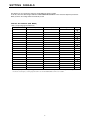
FACTORY SET SIGNALS (RGB MODE)
Main corresponding signals (RGB mode)
Display (dots x lines)
Horizontal frequency (kHz)
Vertical frequency (Hz)
Signal
640 x 480
31.47
59.94
VGA
640 x 480
37.50
75.00
VGA 75 Hz
640 x 480
43.27
85.01
VGA 85 Hz
720 x 400
31.47
70.09
400 lines
800 x 600
37.88
60.32
SVGA 60 Hz
800 x 600
46.88
75.00
SVGA 75 Hz
800 x 600
53.67
85.06
SVGA 85 Hz
1024 x 768
48.36
60.00
XGA 60 Hz
1024 x 768
60.02
75.03
XGA 75 Hz
1024 x 768
68.68
84.99
XGA 85 Hz
1280 x 1024
63.98
60.02
SXGA 60 Hz
1280 x 1024
79.98
75.03
SXGA 75 Hz
1600 x 1200
75.00
60.00
UXGA 60 Hz
1600 x 1200
106.25
85.00
UXGA 85 Hz
848 x 480
31.02
60.00
852 x 480
31.72
59.97
1360 x 768
47.71
60.01
720 x 485
15.73
59.94
60 fields
720 x 575
15.63
50.00
50 fields
DVI-D
* With some input signals, “Out of range” may appear even when the horizontal and vertical frequencies are within their permissible ranges. Make
sure that the vertical frequency of the input signal is 85 Hz or less for SVGA/XGA/UXGA, 75 Hz or less for SXGA.
-5-
FACTORY SET SIGNALS (Component video mode)
Horizontal
frequency (kHz)
Vertical
frequency (Hz)
FACTORY SET SIGNALS (Video, S-video mode)
Horizontal
frequency (kHz)
Signal
Vertical
frequency (Hz)
Signal
15.73
59.94
SDTV 480i
15.73
59.94
NTSC
15.63
50.00
SDTV 576i
15.63
50.00
PAL
31.47
59.94
SDTV 480p
15.63
50.00
SECAM
31.25
50.00
SDTV 576p
15.63
59.52
PAL 60
45.00
60.00
HDTV 720p
15.63
50.00
N-PAL
37.50
50.00
HDTV 720p
15.73
59.95
M-PAL
33.75
60.00
HDTV 1,080i
15.73
59.94
4.43 NTSC
28.13
50.00
HDTV 1,080i
In the 800 x 600 and 1,024 x 768 modes, images of reduced size are displayed on the screen, using size reduction and
interpolation. Also note that on-screen information is also displayed in reduced size.
" Out of range" appears if the display receives a signal whose characteristic does not fall within the display's
permissible range.
You can check the input signals with "Information" on the OTHERS Menu screen.
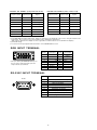
RGB INPUT TERMINAL
∗ The sync switch (TTL/ANALOG switch) is on
the rear of the 13-pin horizontal sync and
14-pin vertical sync terminals.
Pin No.
Input signal
Pin No.
1
2
3
4
5
6
7
8
Red
Green
Blue
9
10
11
Ground
Ground
Ground
Ground
12
13
14
15
Outer side
Input signal
Ground
Horiz. sync
Vert. sync
Ground
RS-232C INPUT TERMINAL
Pin No.
No. signal
Pin No.
1
2
3
4
5
6
7
8
9
DCD (Data Carrier Detect)
RD (Receive Data)
TD (Transmit Data)
DTR (Data Terminal Ready)
GND (Ground)
DSR (Data Set Ready)
RTS (Request To Send)
CTS (Clear To Send)
RI (Ring Indication)
-6-
CONNECTION
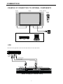
EXAMPLE OF CONNECTION TO EXTERNAL COMPONENTS
Speaker
Speaker (optional)
Display
Remote
control
VCR
PC
VCR
Connect the video signal cable to either the S-video input terminal or the video input terminal.
To audio
output
To video output
To S-video output
To audio input
To S-video input
To video input
Bottom of Display (Ex.: P42VCA11 series)
-7-
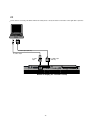
PC
As the cable for connecting a PC differs with the PC model, please consult your dealer for information on the right cable to purchase.
To RGB output (mD-sub)
To audio output
To audio
input
To RGB1 input
(mD-sub)
Bottom of Display (Ex.: P42VCA11 series)
-8-
* Video board nothing
EXAMPLE OF CONNECTION TO EXTERNAL COMPONENTS
Speaker
Speaker (optional)
Display
Remote
control
PC
-9-
PC
As the cable for connecting a PC differs with the PC model, please consult your dealer for information on the right cable to purchase.
To RGB output (mD-sub)
To audio output
To audio
input
To RGB1 input
(mD-sub)
Bottom of Display (Ex.: P42VCA11 series)
- 10 -
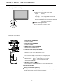
PART NAMES AND FUNCTIONS
Front (both 42" and 50")
Power indicator lamp
This lamp shows the state of the power supply.
Lit (red):
Stand-by
Lit (green):
Power ON
Lit (orange):
Power saving (DPMS: Power saving
function) mode ON
Flashing (red): Malfunction (Flashes differently depending
on the type of malfunction.)
Remote control signal receiver
Receives signals from the remote control.
REMOTE CONTROL
RGB
Power ON button [POWER ON]
Turns the power ON.
POWER OFF
ON
POWER
VIDEO
WIDE
Power OFF button [POWER OFF]
Turns the power OFF.
RGB input mode selector button [RGB]
Switches between RGB input modes.
MENU
VOL
Video input mode selector button [VIDEO]
Switches between video input modes.
ENTER
Wide screen selector button [WIDE]
Switches the screen over to a desired wide screen.
SHIFT
1
Menu button [MENU]
Use this button to display a desired menu for adjusting the picture.
2
3
10
Volume adjustment buttons [VOL +/-]
Adjust the volume. Press the + button to increase the volume.
Press the - button to reduce the volume.
* Not used with P50XCA10.
4
Adjustment buttons [ / / / ]
Use these buttons to scroll through options in a menu and change values.
Enter button [ENTER]
Press this button to finalize the selection of a desired menu or option within a menu.
10
Display selector buttons [SHIFT 1-4]
When you use two or more displays, you can use these buttons to control up to four
displays by assigning an unique number to each display.
- 11 -
* Video board nothing
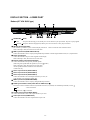
DISPLAY SECTION – LOWER PART
Bottom (42" VCA 20/21 type)
OFF/STD-BY
switch
OFF
:The power indicator lamp goes off, and the power can' t be turned on by the power button. The power is partly supplied.
STD-BY
:The power indicator lamp lights red, and the power can be turned on or off by the power button.
RS-232C terminal (RS-232C)
This terminal is provided for you to control the display from the PC. Connect it to the RS-232C terminal on the PC.
When connecting a cable, attach a ferrite core to the cable.
RGB1 input terminal (RGB1 INPUT/mD-sub)
Connect this terminal to the PC's display (analog RGB) output terminal or decoder (digital broadcast tuner, etc.) output terminal.
Power input terminal
Connect this terminal to the power cable supplied with the display.
When connecting a cable, attach a ferrite core to the cable.
External speaker output terminal (EXT SP)
Connect this terminal to the optionally available speaker.
(When using other speaker than the optional one, use 4-16
When connecting a cable, attach a ferrite core to the cable.
*See the speaker instruction manual for more information.
* P42VCA21 only.
speaker.)
Sound 1 input terminal (AUDIO1 INPUT)
Sound 2 input terminal (AUDIO2 INPUT)
Sound 3 input terminal (AUDIO3 INPUT)
Connect this terminal to the sound output terminal of your computer, etc.
* This terminal is not available for P42VCA20.
RGB2 input terminal (RGB2 INPUT/BNC)
Connect this terminal to the PC’s display (analog RGB) output terminal or decoder (digital broadcast tuner,etc.) output terminal.
RGB2 synchronization switch (SYNC SW TTL/ANALOG (75 ))
This switch is used to terminate horizontal (H) terminal and vertical (V) terminal, out of RGB2 input terminals, with 75
TTL
ANALOG (75
: Does not terminate.
): Terminates.
- 12 -
.
DISPLAY SECTION – LOWER PART
Bottom (42" VCA 20/21/ type)
OFF/STD-BY
switch
OFF
:The power indicator lamp goes off, and the power can' t be turned on by the power button. The power is partly supplied.
STD-BY
:The power indicator lamp lights red, and the power can be turned on or off by the power button.
RS-232C terminal (RS-232C)
This terminal is provided for you to control the display from the PC. Connect it to the RS-232C terminal on the PC.
When connecting a cable, attach a ferrite core to the cable.
RGB1 input terminal (RGB1 INPUT/mD-sub)
Connect this terminal to the PC's display (analog RGB) output terminal or decoder (digital broadcast tuner, etc.) output terminal.
Power input terminal
Connect this terminal to the power cable supplied with the display.
When connecting a cable, attach a ferrite core to the cable.
External speaker output terminal (EXT SP)
Connect this terminal to the optionally available speaker.
(When using other speaker than the optional one, use 4-16
When connecting a cable, attach a ferrite core to the cable.
*See the speaker instruction manual for more information.
* P42VCA21 only.
speaker.)
Sound 1 input terminal (AUDIO1 INPUT)
Sound 2 input terminal (AUDIO2 INPUT)
Sound 3 input terminal (AUDIO3 INPUT)
Connect this terminal to the sound output terminal of your VCR, etc.
* This terminal is not available for P42VCA20.
RGB2 input terminal (RGB2 INPUT/BNC)
Connect this terminal to the PC’s display (analog RGB) output terminal.
RGB2 synchronization switch (SYNC SW TTL/ANALOG (75 ))
This switch is used to terminate horizontal (H) terminal and vertical (V) terminal, out of RGB2 input terminals, with 75
TTL
ANALOG (75
: Does not terminate.
): Terminates.
S-Video input terminal (S-VIDEO INPUT)
Connect this terminal to the S-video output terminal of your VCR.
Video input terminal (VIDEO INPUT)
Connect this terminal to the video output terminal of your VCR.
- 13 -
.
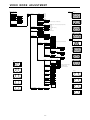
VIDEO MODE ADJUSTMENT
Position
REMOTE CONTROLLER
POWER ON
MENU
POWER OFF
PICTURE
ENTER
RGB
RGB 1
RGB 2
VIDEO
Video
S-video
{-30 to +30}
Brightness
{-60 to +60}
Color
{-60 to +60}
Tint
{-30 to +30}
Sharpness
{-16 to +16}
Picture Mode
Normal
Wide 1
Wide 2
Zoom 1
Zoom 2
WIDE
Contrast
Horizontal "+"
Dynamic
Real
Static
Luminance*
{40 to 100%} *Can be set when Static is selected as the Picture Mode.
VOL. +
Color Temp.
{-3500 to +3500}
VOL. -
User Color Temp.*
Red
Green
Blue
{0 to 255} *Can be set when User is selected as the Color Temp.
{0 to 255}
{0 to 255}
Position
Horizontal
Vertical
{-30 to +30}
{-7 to +7 (Zoom -15 to +15)}
Width
Height
{-7 to +16}
{-7 to +16}
POSITION/SIZE
Size
AUDIO*
Horizontal "-"
Treble
{-6 to +6}
Bass
{-6 to +6}
Balance
{-10 to +10}
Vertical "-"
*Cannot be set with P42VCA20
Vertical "+"
FEATURES
On
Off
On Screen Menu
OSD
On
Off
Language
English
Deutsch
~
Espanol
Francais
Italiano
Portugues
Pycc K NN *
Size
Width "-"
~
Loudness
<
Input Terminal
Video Input
S-video Input
BNC Input
*Russian can only be set with the E-model.
Auto
NTSC
PAL
SECAM
PAL60
4.43NTSC
RGB-Video
Width "+"
Mask
Off
5
10
15
Mask
Off
5
10
15
RGB-PC
Decoder
D-SUB Input
Others
DPMS
RGB-PC
Decoder
Mask
Time
Off
1 min.
15 min.
45 min.
60 min.
Background
Black
White
RGB 1
No Audio
Audio 1
Audio 2
Audio 3
Normal
Audio Input*
RGB 2
Wide 1
Height "-"
Video
Off
5
10
15
Height "+"
*Audio Input menu will not be displayed
when "No Audio"is selected.
*Cannot be set with P42VCA20.
S-video
Input Priority
Wide 2
Off
RGB 1
RGB 2
Video
S-video
Monitor No.
0
1
2
3
4
White Screen
On
Off
Mask Off
Mask 5
Zoom 1
Exhibition Mode
On
Off
Installation
-90 Deg.
Normal
+90 Deg.
Information
Mode
Monitor No.
Freq. Scan Mode
Input Signal
Freq.
Zoom 2
FACTORY DEFAULT
Execute
Mask 10
Yes
No
Mask 15
- 14 -
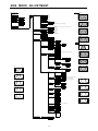
RGB MODE ADJUSTMENT
Position
REMOTE CONTROLLER
POWER ON
MENU
POWER OFF
PICTURE
ENTER
RGB
RGB 1
RGB 2
VIDEO
Video
S-video
{-30 to +30}
Brightness
{-60 to +60}
Color
{-60 to +60}
Tint
{-60 to +60}
Sharpness
{-4 to +4}
Picture Mode
Normal
Wide 1
Wide 2
Zoom 1
Zoom 2
WIDE
Contrast
Horizontal "+"
Dynamic
Real
Static
Luminance*
{40 to 100%} *Can be set when Static is selected as the Picture Mode.
VOL. +
Color Temp.
{-3500 to +3500}
VOL. -
User Color Temp.*
Red
Green
Blue
{0 to 255} *Can be set when User is selected as the Color Temp.
{0 to 255}
{0 to 255}
Position
Horizontal
Vertical
{-150 to +150}
{-150 to +150}
Width
Height
{-25 to +50}
{-25 to +50}
POSITION/SIZE
Size
AUDIO*
Horizontal "-"
Treble
{-6 to +6}
Bass
{-6 to +6}
Balance
{-10 to +10}
Vertical "-"
*Cannot be set with P42VCA20
Vertical "+"
FEATURES
Loudness
On
Off
Adjustment
Dot Clock
Clock Phase
Clamp Position
On Screen Menu
{-60 to +60}
Auto
Manual
{1 to 32}
{-8 to +8}
Size
Execute
OSD
On
Off
Language
English
Deutsch
~
Espanol
Francais
Italiano
Portugues
Pycc K NN
Width "-"
Yes
No
Width "+"
~
Auto Calibration
<
Input Terminal
Video Input
S-video Input
BNC Input
*Russian can only be set with the E-model.
Auto
NTSC
PAL
SECAM
PAL60
4.43NTSC
RGB-Video
Height "-"
Mask
Off
5
10
15
Mask
Off
5
10
15
RGB-PC
Decoder
Normal
D-SUB Input
Others
DPMS
RGB-PC
Decoder
Mask
Time
Off
1 min.
15 min.
45 min.
60 min.
Background
Black
White
RGB 1
No Audio
Audio 1
Audio 2
Audio 3
Wide 1
Audio Input*
RGB 2
Wide 2
Height "+"
Video
Off
5
10
15
*Audio Input menu will not be displayed
when "No Audio"is selected.
*Cannot be set with P42VCA20.
Mask Off
S-video
Screen Orbiter
Mode / Time
Off
Time
Mode
Moving Area
Min.
Std.
Max.
Zoom 1
Zoom 2
FACTORY DEFAULT
Execute
Input Priority
Off
RGB 1
RGB 2
Video
S-video
Monitor No.
0
1
2
3
4
Direct Setting
Auto
VGA
WVGA
480P
XGA
WXGA
SXGA
SXGA+
Code Setting
Auto
Manual
White Screen
On
Off
Exhibition Mode
On
Off
Installation
-90 Deg.
Normal
+90 Deg.
Information
Mode
Monitor No.
Freq. Scan Mode
Input Sync
Freq.
Preset No.
Yes
No
- 15 -
Mask 5
Mask 10
Mask 15
{00 to 34} *Hexadecimal
TROUBLESHOOTING USING LED AND OSD
1. Display
(1) OSD
Three kinds of error messages are displayed on the screen, and the power is turned off 10 sec later.
(2) LED
LED error is displayed continuously after the power is turned off.
2. Error types and check points
(1) OSD
On screen display
ERROR MESSAGE CONDITION 1
ERROR MESSAGE CONDITION 2
Cause
Fan protector operated
Temperature protector
operated
Check point
Fan
Main power PCB
Main/Digital PCB
Ambient temperature of unit
Main/Digital PCB
Temp. sensor IC757
(2) LED
LED lamp display status
Steady light (Red)
Continuous
Flashes continuously (Red)
1 time
Flashes once every 4 sec. (Red)
2 times
Flashes twice every 5 sec. (Red)
Cause
Stand-by status
No power
Power supply protector
operated
Fan protector operated
Temperature protector
operated
EEPROM error
3 times
Flashes three times every 6 sec. (Red)
Main/Digital circuit faulty
5 times
Flashes five times every 8 sec. (Red)
- 16 -
Check point
Main power PCB
PDP panel
Fan
Main power PCB
Main/Digital PCB
Ambient temperature of unit
Temperature sensor IC757
Main/Digital PCB
Main/Digital PCB
Video PCB
Video PCB
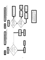
TROUBLESHOOTING FLOWCHART
LED lamp blinking
Note : 1. Since a voltage is applied to the Main Power
PCB heat sinks while the set is operating, do
not touch the heat sinks.
2. If the Main Power PCB insulation sheet is not
installed when assembling, the Main Power
PCB fuse will blow.
Turn power on and check
state of lamp.
LAMP STATE
POWER SUPPLY STATE
Not lighted.
Power supply
PCB faulty.
Check PDP Panel.
Blinks continuously.
Power turned off
immediately.
Check PDP Panel.
Blinks once
Power turned off
after 10 sec.
Check 1
Blinks twice
Power turned off
after 10 sec.
Check 2
Blinks four times
Power not turned
off, LED blinks only.
Replace Main/Digital
PCB Assy.
Blinks five times
Power not turned
off, LED blinks only.
Replace Video PCB
Assy.
RED
RED
RED
RED
RED
GREEN
REMEDY
Lights steadily for
more than 10 sec.
Is on-screen display
normal?
NO
Check PDP Panel.
YES
All input image
faulty.
Signal processing
PCB faulty.
Replace Main/Digital
PCB Assy.
Video input image
faulty.
Video PCB faulty.
Replace Video PCB
Assy.
S-video input image
faulty.
Video PCB faulty.
Replace Video PCB
Assy.
Component video
input image faulty.
Signal processing
PCB faulty.
Replace Main/Digital
PCB Assy.
RGB input image
faulty.
Check 3
- 17 -
- 18 -
Fan faulty
Yes
14V?
2 and 3 on Main PCB
connectors CN352
Is voltage at
Start
Check 1
Replace fan.
No
Replace Main/
Digital PCB Assy.
Microcomputer
peripheral
circuit faulty.
Power lamp: Flashes once intermittently in red.
(For 0.5 sec. at an interval of 4 sec.)
Fan protector operated
Yes
Microcomputer
peripheral circuit
faulty.
Temperature
sensor IC757 faulty.
No
No
The temperature sensor IC757 is installed
on Main/Digital PCB. Turn the power off
and cool with a point cooler.
Replace
temperature sensor
IC757.
Replace
Main/Digital
PCB Assy.
Adjust PDP unit installation so that
peripheral temperature is 40.0 C or
less.
Temperature sensor cooling
Does unit
operate normally
when temperature sensor
IC757 changed ?
Yes
Temperature protector operated
Power lamp : Flashes intermittently twice in red.
(For 0.5 sec. at an interval of 5 sec.)
Is ambient temperature
of IC757 on Main/Digital
PCB less than 60 C ?
Start
Check 2
- 19 -
No
Replace Main/Digital PCB Assy..
Signal processing circuit faulty..
Yes
Is input level(∗)
∗ within specified
range ?
Yes
Is frequency of horizontal sync.
and vertical sync. signals
Yes
Yes
No
No
Check input signal.
Check input signal.
Is sync. signal
TTL and polarity
negative?
Check input signal.
Separate signal
Connect RGB cable
to terminal.
Is Sync. switch
No
(TLL/ANALOG) selected
correctly ?
Yes (ANALOG)
Yes
RGB input is abnormal.
Power lamp: Lighted green
(10 sec or more)
Is horizontal sync.
signal input to pin 13 and vertical sync.
signal input to pin 14 of
RGB cable ?
Check 3
No
Check input signal.
No
Yes
Is composite sync.
signal input to pin 2 of RGB
cable ?
Make sync. signal polarity output
from signal source negative, or make
output impedance TTL.
Change sync. switch (TTL/ANALOG)
Composite signal
Check connection cable.
Note(∗): If the synchronizing signal cannot be identified by
TTL level, it is in the 75Ω terminated state.
Yes
Is composite sync.
signal input to pin 2 of RGB
cable ?
Sync. on green signal
What kind of
signal is output from signal
source ?
Yes
Is RGB
cable pin arrangement
appropriate ?
Start
No
EXPLANATION OF LABELS
Panel Label Information
M
*****
Panel Part Number
No.
Panel Serial Number
**********
***** V Vsus : ***** V
Vbk :
***** V Vad : ***** V
MADE IN JAPAN
*. * .*
Ve :
Adjustment Voltage
Panel Production Date
Panel Production Date
For Example---------1.8.2
1
Year
8
Month
2
9 : 1999 1 : JAN 1 : Beginning of Month(01-10th)
0 : 2000 2 : FEB 2 : Middle of Month (11-20th)
1 : 2001 3 : MAR 3 : End of Month
(21-31st)
2 : 2002
9 : SEP
0 : OCT
N : NOV
D : DEC
Unit Serial Number
For Example----------- YA1450001
YA 1 4 5 0001 * MID/AUG/2001
5 * YA Production Line
1 2 3 4
1 Production Line No.
2 Production Year
1 : 2001
2 : 2002
3 Production Month
1 : JAN-FEB
2 : MAR-APR
3 : MAY-JUN
4 : JLY-AUG
5 : SEP-OCT
6 : NOV-DEC
4 Production Period (Day)
1st Month
1 : BEG (1-10)
2 : MID (11-20)
3 : END (21-30/31)
2nd Month
4 : BEG (1-10)
5 : MID (11-20)
6 : END (21-30/31)
5 Serial Number
From 0001-----
- 20 -
REPLACEMENT PARTS AND REQUIRED ADJUSTMENT
Caution
To remove PCB, wait for 1 minute after power was turned off for electrolytic capacitors to discharge.
Preparation
Wide------------------ Auto
Input------------------ White pattern
Quick adjustment after PCB replacement
PCB
Power Supply PCB
Scan Drive PCB
Sustain Drive PCB
Item
Vsus
Test Point
TPVSUS
Level
170V ± 1V
Vda
TPVDA
67V ± 1V
Vbk
Vad
Ve
TPVBK
TPVAD
TPVE
155V ± 5V
-90V ± 1V
150V ± 1V
- 21 -
VR
R540
R621
R537
R646
R6443
R6477
R6774
Remarks
W, E Type
U Type
W, E Type
U Type
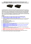
VR AND TEST POINT LOCATION
Adjustment VR Location
R646/Vda R537/Vda
(U Type) (W, E Type)
R6443/Vbk
R540/Vsus
(W, E Type)
R621/Vsus
(U Type)
R6523
R6774/Ve
R6557
R6477/Vad
Test Point Location
Label (Panel Information)
Label (Serial Number for Unit)
TPVDA
TPVSUS
TPVBK
TPVE
TPSC1
TPVAD
TPSS1
TPVSCN
TPVSET
- 22 -
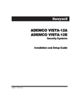
- 23 -
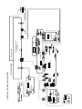
92 FUN
TERMINAL
LED/PHOTO AMP
M02GUB
M02HWB
92 FUN
INLET
PFC
M021B
MAIN/DIGITAL
M02AF
M02HWA
P42VCA20WH/EH
GENERAL CONNECTION DIAGRAM
CONNECTION
M02HWG
DC/DC
PLASMA DISPLAY UNIT
MD-42HM5E
OPTICAL FILTER
M02GG
(OPTIONAL)
VIDEO
POWER ON/OFF SWITCH
M02GUC
- 24 -
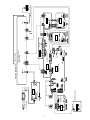
92 FUN
TERMINAL
LED/PHOTO AMP
M02GUB
M02HWB
92 FUN
INLET
PFC
M021B
MAIN/DIGITAL
M02AF
M02HWA
P42VCA20UH
CONNECTION
M02HWG
DC/DC
M02GG
VIDEO
(OPTIONAL)
PLASMA DISPLAY UNIT
MD-42HM5U
OPTICAL FILTER
POWER ON/OFF SWITCH
M02GUC
- 25 -
M02GUB
M02HWB
92 FUN
M02IB
PFC
LED/PHOTO AMP
TERMINAL
92 FUN
INLET
MAIN/DIGITAL
M02AF
M02HWA
P42VCA21WH/EH
CONNECTION
M02HWG
PLASMA DISPLAY UNIT
MD-42HM5E
OPTICAL FILTER
DC/DC
VIDEO
M02GG
M02HWF
AUDIO TERMINAL
M02HWD
AUDIO
POWER ON/OFF SWITCH
M02GUC
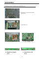
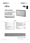
DISASSEMBLY
1. Removing the Rear Case and layout of Main PCB (1 of 2)
1. Remove the 32 circled screws and remove
the Rear Case.
J
A
* Layout of Main PCB.
D
F
I
E
C
H
B
G
A: Main Digital PCB
B: Data Drive (Right)
PCB
C: Data Drive (Left)
PCB
- 26 -
1. Removing the Rear Case and layout of Main PCB (2 of 2)
D: Scan Drive Output
(Upper) PCB
E: Scan Drive Output
(Lower) PCB
F: Scan Drive PCB
G: Sustain Drive PCB
H: Power Supply PCB
I: Digital PCB
J: Audio Main PCB
- 27 -
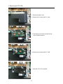
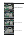
2. Removing the PFC PCB
1. Remove the Rear Case.
2. Remove the 2 screws and PFC cover.
3. Take away the insulator and Disconnect
the 2 circled connectors.
4. Remove the 4 screws and PFC PCB.
* View after PFC PCB removed.
- 28 -
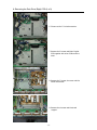
3. Removing the Main Digital PCB (1 of 2)
1. Remove the Rear Case.
2. Remove the 1 screw and DC/DC PCB.
3. Disconnect the 1 circled connector.
4. Remove the 3 screws and I/O PCB.
5. Disconnect the 9 circled connectors.
- 29 -
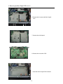
3. Removing the Main Digital PCB (2 of 2)
6. Remove the 9 screws and Main Digital
Unit.
7. Remove the shield panel.
8. Remove the connection PCB.
* View after Main Digital PCB removed.
- 30 -
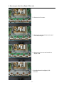
4. Removing the PDP Unit (1 of 3)
1. Perform the procedure 1 ~ 4 in P35.
2. Disconnect the 1 circled connector and
the 2 wire clampers.
3. Remove the Base Frame from the Front
Case together with the panel and PCBs.
* View after removal of the Base Frame
from the Front Case.
4. Perform the procedure 5 ~ 8 in P35, 36
2 ~ 3 in P44.
- 31 -
4. Removing the PDP Unit (2 of 3)
5. Remove the 2 fans.
6. Remove the 6 screws and 2 Fan Plinth.
7. Remove the 4 screws and 2 bracket bars.
8. Take away the insulator and Disconnect the
1 circled connector.
- 32 -
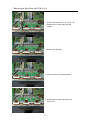
4. Removing the PDP Unit (3 of 3)
* View after only the PDP Unit removed.
* When the PDP Unit is replaced, make
sure to replace the removed parts to
their original position.
- 33 -
5. Removing the Audio PCB
1. Remove the Rear Case.
2. Disconnect the 4 circled connectors.
3. Remove the 4 screws and Audio PCB.
* View after Audio PCB removed.
- 34 -
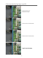
6. Removing the Data Drive (Right) PCB (1 of 3)
1. Remove the PFC PCB.
(To remove the PFC PCB, refer to the
Page 28)
2. Take away the insulator and Disconnect
the 4 circled connectors.
3. Remove the 7 screws.
4. Remove the 9 screws and the cover.
5. Remove the I/O PCB.
- 35 -
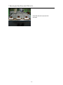
6. Removing the Data Drive (Right) PCB (2 of 3)
6. Disconnect the 7 circled connectors.
7. Remove the 5 screws and Main Digital
PCB together with other PCBs and the
cover.
8. Remove the 7 screws, the cover and the
center bracket bar.
9. Remove the 4 screws and the stand
support.
- 36 -
6. Removing the Data Drive (Right) PCB (3 of 3)
10. Remove the 10 screws.
11. Disconnect the 7 circled connectors and
the 2 wire clampers.
12. Remove the 4 screws and Data Drive
(Right) PCB.
* View after Data Drive (Right) PCB
removed.
- 37 -
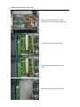
7. Removing the Data Drive (Left) PCB (1 of 2)
1. Perform the procedure 1 ~ 8 in P35 ~ 36.
2. Remove the 4 screws and the stand
support.
3. Remove the 8 screws.
4. Disconnect the 5 circled connectors.
5. Remove the 4 screws and Data Drive
(Left) PCB.
- 38 -
7. Removing the Data Drive (Left) PCB (2 of 2)
* View after Data Drive (Left) PCB
removed.
- 39 -
8. Removing the Scan Drive Output (Upper / Lower) PCB
1. Remove the Rear Case.
2. Remove the 4 screws.
3. Disconnect the 4 circled connectors.
4. Disconnect the 6 circled connectors.
* View after Scan Drive Output
(Upper / Lower) PCB removed.
- 40 -
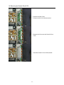
9. Removing the Scan Drive PCB
1. Perform the procedure 1 ~ 3 in P40.
2. Remove the 7 screws and 2 bracket bars.
3. Disconnect the 4 circled connectors.
4. Remove the 9 screws and Scan Drive
PCB.
* View after Scan Drive PCB removed.
- 41 -
10. Removing the Sustain Drive PCB
1. Remove the Rear Case.
2. Disconnect the 10 circled connectors.
3. Remove the 10 screws and Sustain Drive
PCB.
* View after Sustain Drive PCB removed.
- 42 -
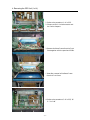
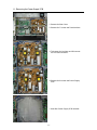
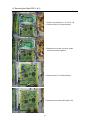
11. Removing the Power Supply PCB
1. Remove the Rear Case.
2. Remove the 7 screws and 2 bracket bars.
3. Take away the insulator and Disconnect
the 8 circled connectors.
4. Remove the 8 screws and Power Supply
PCB.
* View after Power Supply PCB removed.
- 43 -
12. Removing the Digital PCB (1 of 2)
1. Perform the procedure 1 ~ 8 in P35 ~ 36.
2. Disconnect the 3 circled connectors.
3. Remove the 4 screws, the cover, Audio
PCB and the wires together.
4. Disconnect the 7 circled connectors.
5. Remove the 4 screws and Digital PCB.
- 44 -
12. Removing the Digital PCB (2 of 2)
* View after Digital PCB removed.
- 45 -
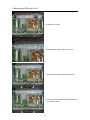
13. Removing the Bezel Front
1. Remove the 2 circled Cover Stands and
remove the screws in the holes.
2. Lift the bottom of the Bezel Front.
3. Lift the Bezel Front upward to
remove it.
(The top of the Bezel Front is
hooked.)
* View after Bezel Front was removed.
- 46 -
14. Removing the Optical Filter
1. Remove the Bezel Front.
(To remove the Bezel Front, refer to
the Page 46)
2. Remove the 14 screws on the Filter
Holders at each side.
3. Remove the Filter Holders by sliding
them in the arrow directions.
4. Remove the Optical Filter.
- 47 -
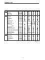
PARTS LIST
Ref.no.
Description
Cabinet Bezel Front
Case Rear
Cover Stand
Holder Filter L/R
Holder Filter T/B
Electric Fan Motor
Optical Filter
PFC PCB
Connection PCB
DC/DC PCB
I/O PCB
LED/PHOTO PCB
Main Digital PCB
Audio Main PCB
Audio Connection PCB
PDP Unit
Power Cord VDE
UL.CSA
Remote Control Unit
Panel Glass
Data Drive Right PCB (C1)
Data Drive Left PCB (C2)
Scan Drive Output (Upper) PCB (SU)
Scan Drive Output (Lower) PCB (SD)
Scan Drive PCB (SC)
Sustain Drive PCB (SS)
Power Supply PCB (P1)
Digital PCB (D)
Packing Carton Top
Carton Bottom
Packing Joint-D
Packing Pad-Top
Packing Pad-Bottom
Carton Accessory
Insheet
P42VCA20WH P42VCA20EH P42VCA20UH P42VCA21WH P42VCA21EH
8112000000
8116117001
8108298008
8110619006
8110614001
8900298008
8112396004
8116351009
8116031000
8115971000
8115964002
8116354000
8116342007 8116343004
----------------------------------------S141011975
8112527002
--------------------8108442005
S141011944
S141011838
S141011845
S141011852
S141011869
S141011920
S141011937
S141011913
S141011890
8116344001
--------------------S141011968
----------8112528009
8116326007 8116324003
8115973004
8116171003
S141011975
8112527002
---------------------
S141011906 S141011913
8115319000
8114547008
8108655009
8114551005
8114550008
8111799004
8111634008
: Same as left
- 48 -
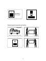
TRANSPORTATION AND HANDLING RESTRICTIONS
Transportation
Bad loading
Don't load the plasmavision on a truck
as shown in the drawing.
Handling
Never topple.
Never drop.
Drop
Over 30 cm
Don't hold the
surface of the
optical filter.
- 49 -
Floor
4
Don't stack the
plasmavision over
three units high.
Example of good transportation and handling
Good loading
Load the plasmavision as shown above.
3
- 50 -
FUJITSU GENERAL CUSTOMER SERVICE LIMITED
GLOBAL SUPPORT DIVISION
FEBRUARY 2003