1
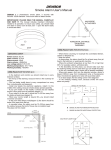
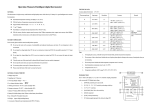
Full Automatic Intelligent Digital Tire Nitrogen Machine
FS-6000B
Operation Instruction Manual
Please read this manual before carrying out any assembly or service procedures.
1
Contents
I.
Introduction
II.
Summarization
III.
Technical Specification
IV.
Integer Appearance Drawing
V.
Control Panel
VI.
Installation
VII.
How to operate
VIII.
Safety Regulations
IX.
Common Faults and Elimination
X.
Guarantee Service
XI.
Equipment and Packing List
APPENDIX A – SERVICE MANUAL
APPENDIX B – CALIBRATION
2
Thank you very much for purchasing Nitrogen Producing Testing Series. In order to
acquire the best performance of the products, please read the instruction manual carefully
and keep it properly for the further reference.
Precaution Instruction
Warning:
To prevent the electric shock and fire, please do not expose the equipment in
the rain and humidity.
Warning:
To prevent the fire dangers caused by absorption of Nitrogen and Oxygen,
please install the equipment in a place with good ventilation.
Warning:
For safety sake, please connect the equipment to the ground wire.
Warning:
Some electronic components are 220V~ in the machine. Please cut off the
power supply in the case of maintenance and repair.
Notice:
Please call our Local Sales Agent if you require service.
Conversion: 1Bar=1.0197Kg/cm2=100Kpa=14.5Psi
Special Explanation:
The warranty period is 12 months. If the user does not install and use the instrument
according to the instruction manual, or use the compressed air with high moisture, refit and
add some parts, and dismantle privately without permission, the manufacturer would not be
responsible for the faults caused by the above abused operations.
Designs and specifications are subject to change without notice
or obligation.
3
FS-6000B
I.
USER’S MANUAL
Brief Introduction
PSA(Pressure Swing Adsorption)Tire Nitrogen Machine, being used widely, does not need
high cost equipments, land and high salary maintenance technicians, but it can produce
Nitrogen with low cost, high purity and low dew point.
It is based on using the latest PSA technology and utilizes Carbon Molecular Sieve (CMS) to
separate nitrogen from the other gases contained in air. When the air is compressed, N2 and
O2 make up of most part of the air, however, oxygen molecules are much smaller than
nitrogen and their diffuse speed is different, by using this point, the gas can be separated.
After this process is finished, the CMS adsorbs the oxygen molecules, so the nitrogen
produced by PSA has high purity and low dew point. Generally speaking, it is very easy to
obtain the nitrogen with purity 99% and dew point -60℃. Our company is able to design and
manufacture according to user’s requirements. The highest purity of nitrogen can be
reached 99%.
II. Summarization
The compressed air in the tire consists 20.9% of oxygen with heavy moisture, and oxygen is
not stable in the tire. When the tire heats, oxygen will permeates through the tire wall. The
test shows that the pervasion can stop till the pressure under the condition of 7 bar and the
oxygen falls by 5%. Oxygen and moisture are harmful to the tire and wheel hub.
III. Technical Data
Vehicle Applicable:
Power Supply:
Power:
Nitrogen Purity:
Input Air Pressure:
Output Nitrogen Pressure:
Nitrogen Producing Speed:
Working Temp:
Test Range:
Breaking Pressure:
Accuracy:
Display Mode:
Dimension:
Configurations:
Motorcycles, Cars, Vans, Mini-Buses and Light Trucks
AC220V 50Hz
60W
95-99.5%
100-145Psi (8-10Bar)
58-100Psi (4-7Bar)
4000-6000L/h
–20℃~+70℃
5~145psi (0.4-9.99Bar)
>145Psi (>9.99Bar )
±1%+0.5psi
115×54(mm)LED display
1400×680×580(mm)
Built-in Electric Control Vacuum Device
120 L Built-in Nitrogen Storage Tank
10 M High Pressure Charge Hose
4
FS-6000B
USER’S MANUAL
IV. Sketch Map of Tire Nitrogen Machine
1. Power Supply Switch
2. Control Panel
3. Compressed Air Inlet
4. Nitrogen Outlet
5. 3-Lay Filtration Device
6. Hose Pothook
V. Control Panel and Functions
5
FS-6000B
USER’S MANUAL
1.
2.
Air Input Pressure Gauge
Nitrogen Output Pressure Gauge
3.
Nitrogen Analogue Purity Display
4.
LED Display Section
5.
Working indicator
6.
7.
ON/OFF:
+:
Turn on and turn off the LED screen
Increase the inflation pressure
8.
-:
Decrease the inflation pressure
9.
Automatic: When operate this step,
Please remove valve core from tire valve first.
Then deflate all the gas of the tire.
Finally connect N2 output charging hose with tire valve.
10.
Cancel:
11.
Measurement switchover(Bar, Psi, Kpa, Kg/cm 2)
Unit:
Psi indicator
Bar indicator
Mpa indicator
Kg/cm2 indicator
12.
13.
14.
15.
Press this key, the equipment will stop working temporarily, press it
again, the equipment continues working. If the working program
needs cancellation, hold the key for 3 seconds, the equipment will
stop working.
Important Notice
The machine starts to produce nitrogen with the Indicator Light on, when the
nitrogen pressure is lower than 58psi or 4bar.
The machine stops producing nitrogen with the indicator light off, while the
nitrogen pressure is higher than 100psi or 7bar.
VI. Installation
1. Air supply Connection:
The machine’s compressed air inlet is connected with air
compressor outlet (The air supply is ≥6000L/H, if the air
supply is not sufficient, the nitrogen producing speed will be
influenced).
2. Power Connection:
Connect with Power Supply 220 V and the ground wire
6
FS-6000B
USER’S MANUAL
VII. How to operate
1.Turn on the power supply on the left side of the main machine and the Control Panel
Switch, the initial value is shown on the screen.
2.Operating methods:
1) Remove valve core from the tire valve, deflate all the gas inside the tire, and then connect
N2 output charging hose clip with tire valve. When tire pressure is “0” bar, and the tire
NEEDS VACUUM, please operate as follows:
Step A.
Press “+” or “-” to set the required pressure (the initial pressure is 28psi or
2bar)
Step B.
Then press AUTOMATIC, the machine will vacuum the tire for 30-40
seconds, after vacuum finishes; the machine will shift to N2 inflation.
Step C.
When it reaches the required pressure, the buzzer will ring.
Step D.
Remove the charging clip and load the valve core at this moment. (During loading
the tire valve, the inner pressure drops, and it needs more inflation).
Step E.
Then connect N2 output charging hose with tire valve till the buzzer rings as well
as “END” shows on the screen, the tire inflation completes.
2) Remove the valve core from the tire valve and deflate all the gas inside the tire, and then
connect N2 output charging hose clip with tire valve. When tire pressure is “0” bar, and the
tire DOESN’T NEED VACUUM, please operate as follows:
Step A.
Press “+” or “-” to set the required pressure (the initial pressure is 28psi or
2bar)
Step B.
Then hold AUTOMATIC for 3-4 seconds, the machine starts to inflate the tire
with N2.
Step C.
When it reaches the required pressure, the buzzer will ring.
Step D.
Remove the charging clip and load the valve core at this moment. (During loading
the tire valve, the inner pressure drops, and it needs more inflation).
Step E.
Then connect N2 output charging hose with tire valve till the buzzer rings as well
as “END” shows on the screen, the tire inflation completes.
7
FS-6000B
USER’S MANUAL
3) When tire pressure >5PSI or >0.3BAR, please operate as follows:
Step A.
Press “+” or “-” to set the required pressure (the initial pressure is 28psi or
2bar)
Step B.
Then connect the N2 charging hose clip with tire valve. The machine will shift to
working condition automatically.
Step C.
When tire pressure is higher (lower) than the required pressure, the machine will
deflate (inflate).
Step D.
When it reaches the required pressure, the buzzer will ring as well as “END”
shows on the screen, the tire inflation completes.
3.Please refer to the instruction manual No. V for more details on the Function keys.
VIII.
Safety Regulations
1.
Heavy nitrogen and oxygen gases can be produced in the process of producing
nitrogen. Suffocation can be caused by inbreathe nitrogen, while the oxygen will
increase the risk of fire; therefore please keep good ventilation in the installation
area.
2.
When connecting gas line system, please make sure the machine is switched off
and under the condition of no high pressures in the system.
3.
The machine must be connected with ground wire reliably; otherwise the normal
use of the machine and the safety of the operator will be impacted.
4.
Check the safety devices and pressure gauge termly in order to keep the working
system normal.
5.
Do not use the unqualified pipes and fittings.
6.
Do not dismantle and assemble any pressure control valves without permits.
8
FS-6000B
IX.
USER’S MANUAL
Faults and Eliminations
Faults
Reasons
Treatments
The air compressor and the
output pressure of the
nitrogen machine is normal,
but there is no indication of
the air input pressure.
1. The solenoid valve does not
work.
2. The air input pressure gauge
is damaged.
3. The air hose between the
machine and the air compressor
1. Check if the power switch is
on.
2. Replace the pressure gauge.
3. Eliminate the cause of hose
blocking up.
was blocked up.
The value between the air
Check if the 3 Lay Filtration core
1. Clean the 3 Lay Filtration
compressor gauge and the
air output pressure is great
different.
has been blocked.
core.
2. Replace the 3 Lay Filtration
core.
Air input pressure exceeds
116psi
The pressure regulating valve is
out of work.
Replace the pressure regulating
valve.
The machine works normally,
but no Nitrogen production
and the machine does not
stop working
1. Leakage appears in the
machine.
2. Carbon molecular solenoid
valve stops working.
1. Check if there is leakage on
connectors and pipes
2. Replace the solenoid valve.
The machine works normally,
but the nitrogen purity is
lower than 95%
The Carbon molecular sieve was
polluted by oil or water.
Replace the Carbon molecular
sieve.
There is no display on the
LED screen.
1. There’s no power on the
transformer or it is damaged.
2. The DC power supply on the
control panel is damaged.
1. Replace the transformer.
2. Replace the control panel
circuit board.
3. Replace the Modules.
3. The module is damaged.
LED background light is on,
The DC power supply on the
Replace the control panel circuit
but “Refill” and “kg/cm ”do
not appear on the screen.
control panel is damaged.
board.
The nitrogen output is low
discharge.
1. The nitrogen storage tank is
low pressure.
2. The inflation solenoid valve is
blocked up.
1. Please wait till the pressure
reaches 5kg/cm 2, and then fill
the tire.
2. Remove off and clean the
solenoid valve or replace the
faulty valves.
Inflation/Deflation pressures
cannot be shown on the
screen.
The pressure sensor failed.
Replace the pressure sensor.
2
9
FS-6000B
X.
USER’S MANUAL
Guarantee service
1. Guarantee service is only restricted for the normal use, we would not guarantee for all
the man-made damages (the user does not install and operate the instrument according
to the manual book, fix the parts or components supplied by other manufacturers, refits
that is not admissive by our company, damages caused by nature calamities,
transportation and other accidents, guarantee period is over).
2. Do not tear the labels and posters concerning the manufacturer and product images, or
we would not supply our guarantee service.
XI.
Machine and Packing List
l
Main Machine
1 Set
l
10m High Pressure Inflation Hose (with universal Charge Clip)
1 Pc
l
Manual Book
1 Pc
10
APPENDIX - A
SERVICE MANUAL
FS-6000B
11
Tire nitrogen inflat or troubl eshoot i ng
I. When connect the power supply with the equipment and power on
the equipment, there’s no display on the equipment.
1. Check the power socket whether there’s 200V power.
2. Check whether it’s flexi bl e on the w
i re of the powe r suppl y.
Solution: Reconnect the power supply wires.
3. Check the power supply switch.
Solution: Replace the power switch
4. Check the lamp on the circuit board.
(1) If the lamp is not lighted on the circuit board, please check the fuse of the circuit
board.
Solution: Replace the same size fuse.
(2)If the lamp on the circuit board is lighted, please check the wire and the wire
socket that connects the display with the circuit board.
Solution: Reconnect the wire or replace the wire and the wire socket.
(3)If the lamp on the circuit board is lighted, and there’s nothing wrong with the
wire and the wire socket, please check the display board.
Solution: Replace the display board.
II. The power switch and working indicator are on, but there’s no
pressure in the compressed air gauge and the equipment can’t produce
Nitrogen.
1. Check whether the connection between air compressor and the inflat or i nl et i s
well connected.
Solution: Connect the pipes between air compressor and the inflat or .
2. Check whether there’s compressed air inside the air compressor (Requirement:
there’s must be over 7BAR inside the compressor pressure tank.)
Solution: Power on the compressor power, make the compressor pressure tank
reach more than 7Bar.
3. Check whether the gas pipe is open between air compressor and the inflat or .
Solution: Open the switch of the gas pipe.
4. Check whether the air filter is bl oc ked.
Solution: Clean the filter cor e or repl ace a new fil ter.
5. Check whether the air input solenoid valve is blocked or damaged.
Solution: Clean he input solenoid valve or replace the solenoid valve.
12
III. The power switch and working indicator are on and there’s pressure
in the compressed air gauge but the equipment can’t produce Nitrogen.
1. Check whether the pipe between air input solenoid valve and the pressure tank is
blocked.
Solution: Clean the pipe or replace the pipe.
2. Check whether the active carbon filter is bl oc ked by oi l and w
a t er .
Solution: Replace the active carbon.
3. Check whether the 3piston 5 way solenoid valve is blocked.
Solution: Replace the 3 piston 5 way solenoid valve.
4. Check whether the CMS is filled w
i th oi l and w
a t er w
h i ch leads to the bl oc k of the
CMS and the rebound valve.
Solution: Replace the CMS tube or the rebound valve.
5. Check whether the flow cont rol val ve is bl oc ked or cl os ed.
Solution: Replace the flow cont rol val ve.
6. Check the pipe connection between air input solenoid valve and the pressure
tank.
Solution: Reconnect the pipe connectors.
IV. The connection of power supply and the gas pipe are well connected,
and there’s pressure in the compressed air gauge but the working
indicator is not lighted and fails to produce nitrogen.
1. Check the air input solenoid valve and the working indicator.
Solution: Replace the air input solenoid valve and working indicator.
2. If there’s no fault of the air input solenoid valve and the indicator please check
whether the pressure inside the pressure tank is lower than 4.5BAR, if that is the
case, it means something wrong with the pressure switch. If the pressure inside the
tank is higher than 4.5BAR, please release the pressure to 4.5BAR, which the
equipment will start to work.
Solution: Replace the pressure switch.
V. The equipment can inflat e and deflate, but fai l to vacuum.
1. Check the connection between the air compressor and the inflat or inl et .
Solution: Connect the pipe between air compressor and the inflat or .
2. Check whether there’s compressed air in compressor (Requirement: air supply by
13
compressor must be higher than 7BAR)
Solution: Power on the compressor, air supply by the air compressor must be higher
than 7 BAR)
3. Check the connection pipe between air compressor and the inflat or .
Solution: Open the pipe switch.
4. Check the air filter to see w
h et her it’ s bl oc ked.
Solution: Clean the filter cor e or repl ace the ai r fil ter.
5. Check the solenoid valve which is ahead of the vacuum generator to see whether
it’s damaged.
Solution: Replace the solenoid valve.
6. Check whether there’s air goes through the silencer, if that is the case, please
dismantle the silencer. If the equipment works well, that means something wrong
with the silencer.
Solution: Clean the silencer or replace the silencer.
7. Check the vacuum valve of the twin solenoid valve.
Solution: Replace the twin solenoid valve assemble.
8. Check whether the air inside the tire is let out and the valve core is taken out.
Solution: Let out all the air inside the tire, and vacuum the tire after take out the
valve core.
VI. The pressure tank leaks automatically, and it fail to contain nitrogen.
1. Check the pipe line between CMS with the pressure tank and the pressure tank.
Solution: Reconnect the pipe line or fix the pr essur e tank.
2. Check whether the leakage is from vent of the 3 piston 5 way solenoid valve.
Solution: Replace the solenoid valve and the rebound valve.
VII. There’s no beeper sound in the keypad or after the inflat i on.
Solution: Replace the beeper.
VIII. There’s no response in the keypad after start up the equipment.
1. Check the wire connection between the circuit board and wire socket.
14
Solution: Reconnect the wire or replace the wire and wire socket.
2. Keypad or the key button is damaged.
Solution: Replace the keypad assembles.
IX. After the tire inflat i on/ deflati on, ther e’s di fference between ac tual
pressure and preset pressure.
1. Check whether there’s leakage in the connection between air chuck and tire
valve as well as pipes.
Solution: ①Reconnect the pipe chuck to insure there’s no leakage between the
air chuck and tire valve, inflat e/ deflate t he t ire aft er that .
②If the pipe chuck is wearing and tearing, please grind the seal ring
which is inside the chuck to 1mm.
③Replace the air chuck and pipe.
2. There’s excursion in the circuit board and sensor.
Solution: Recalibrate the circuit board and sensor.
3. Something is wrong with the circuit board.
Solution: Replace the circuit board.
4. Something is wrong with the pressure sensor.
Solution: Replace the pressure sensor.
V. When the equipment inflat es/ deflates the t ire, the dat a shows on t he
display board are unstable or repeat inflat i on/ deflati on.
1. Check whether there’s leakage in the connection between the air chuck and the tire valve.
Solution: ①Reconnect the pipe chuck to insure there’s no leakage between the air
chuck and tire valve, inflat e/ deflate t he t ire aft er that .
②If the pipe chuck is wearing and tearing, please grind the seal ring which
is inside the chuck to 1mm.
③Replace the air chuck and pipe.
2. There’s excursion in the circuit board and sensor.
Solution: Recalibrate the circuit board and sensor.
3. Something is wrong with the circuit board.
Solution: Replace the circuit board.
15
4. Something is wrong with the pressure sensor.
Solution: Replace the pressure sensor.
5. Check the pipe, twin solenoid valve and tire valve to see whether there’s impurity.
Solution: Clear away the impurity.
6. The spring inside the twin solenoid valve is aging, and disability.
Solution: Replace the twin solenoid valve spring or replace the solenoid valve.
VI. During inflat i on/ deflati on, ther e’s nit rogen comes out and fill sto the
tire, but the display shows “000” or “999”.
1. Something is wrong with the circuit board.
Solution: Replace the circuit board.
2. Something is wrong with pressure sensor.
Solution: Replace the pressure sensor.
3. Check the wire connection between circuit board and pressure tank.
Solution: Reconnect the wire.
VII. When the tire pressure exceeds 0.8bar, the equipment fails to
inflat e/ deflate.
1. Check the connection between air chuck and tire valve.
Solution: Reconnect the air chuck.
2. Check the wire connection between the circuit board and pressure sensor.
Solution: Reconnect the wire between pressure sensor and circuit board.
3. There’s excursion in circuit board or the pressure sensor.
Solution: Recalibrate the circuit board and pressure sensor.
4. Something is wrong with the circuit board.
Solution: Replace the circuit board.
5. Something is wrong with the pressure sensor
Solution: Replace the pressure sensor.
16
Remarks: When inflat i on/ deflati on pr essure i s not accurate or the dat a shows
unstable in the display, go and get a tire. Inflat e/ deflate t he t ire wit hout val ve core.
If the equipment can work without tire valve core that means the air chuck is faulty.
Then remove the seal ring from the air chuck, and use the sandpaper to grind the
seal ring to 1mm or replace the air chuck. If the equipment can’t work without the
tire valve core, please judge the problems according to the above.
17
APPENDIX – B
Steps for calibration
1. Please prepare a tire and a high precision pressure gauge (for testing the tire
pressure). Inflat e the ti re to 4. 1kg/ m 2
2. There must be 5 kg/m2 pressure on the machine before calibration, then power
off the ma chi ne comp l et el y, pl ease ma ke sur e ther e’ s not any pr es sur e i n the
nitrogen output hose.
3. Hold “ + ” and “ - ” simultaneously under the condition of complete
power-off. Then powe r on the ma chi ne. Rel ease “+” and “-” till there’s data
shows on the display to check whether the data is flashi ng bet we en 0. 00- 0. 01 . If it
is not the case, please follow the following steps. (When make calibration, at least
two persons are needed, one is in front of the machine, another one is on the back
of the machine.)
4. Please adjust the W502 on the circuit board, which is blue, and on the head of it,
there’s a yellow screw. Adjust that screw to flash bet we en 0. 00- 0. 01 and i t’ s
completed.
5. Connect the nitrogen output hose with the tire (it has 4.1kg/m2 in the tire).
Leakage is forbidden between the connection of tire and tire valve. Then to check
whether there’s 4.00 on the display. If it is not, please adjust it to 4.00(Adjust W102
or W501 on the circuit board). After the adjustment, remove the tire valve. Repeat
the steps 4-5 twice or three times is ok. Finally, power off the m
a chi ne comp l et el y
and restart the machine.
18