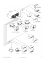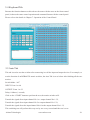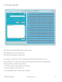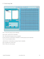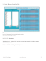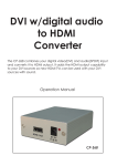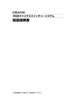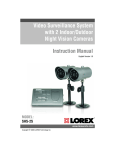
1
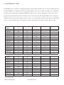
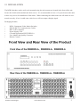
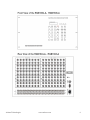
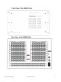
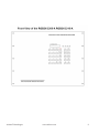
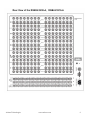
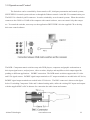
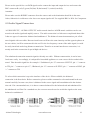
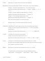
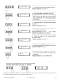
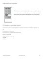
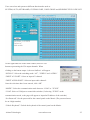
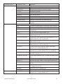
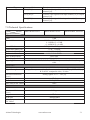
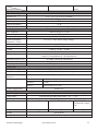
RGB / COMPONENT VIDEO
SWITCHER USER GUIDE
RGB SWITCHERS: AT-RGB0802 TO AT-RGB6464
RGB SWITCHERS W/AUDIO: AT-RGB0802A TO AT-RGB6464A
Atlona Technologies
www.atlona.com
1
Contents
1.0 Safety Operation Guide......................................................................3
1.1 Notice.................................................................................................3
2.0 Introduction........................................................................................4
2.1 Installation..........................................................................................5
3.0 Operation and Control.......................................................................18
4.0 Audio Signal Connection..................................................................19
5.0 Connecting RGB48/642,RGB48/6432,RGB48/6448,RGB6464.....20
5.1 Front Panel/ Control.........................................................................20
5.2 Remote Control Operation................................................................24
5.3 Operation of Application Software...................................................24
5.4 Keyboard Tab...................................................................................26
5.5 Auto Tab...........................................................................................26
5.6 Custom Code Tab.............................................................................27
5.7 Code Group Tab...............................................................................28
5.8 Send / Recieve Code List Tab..........................................................29
6.0 RS-232 Operation.............................................................................29
7.0 Technical Specifications....................................................................31
8.0 Troubleshooting................................................................................33
Atlona Technologies www.atlona.com
2
1.0 Safety Operation Guide
**************************************************************************
In order to ensure the credibility and the user’s safety, please comply with the following items during installation, maintenance and operation of the switch.
1) The switch must be in stable position. Use only the power supply that
comes with unit. Do not use an alternate as it may damage it.
2) Do not place the switcher near hot or cold surfaces or sources.
3) To avoid any damage by over heating, please keep the environment in good
ventilation to radiate the heat when running the switcher.
4) The switcher should be turned off when it is not used.
5) Please do not attempt to take cover off the switcher for there is a high-voltage component inside that could cause electric shock.
6) Do not splash any liquid or chemical on or near the equipment.
7) Please make sure all the wiring are in working condition and are not cut or damaged.
1.1 Notice
**************************************************************************
This RGB Switchers User Manual can be used for other RGB matrix switcher models.
This manual is only an instruction for operators, not for any maintenance usage.
Any changes of functions and parameters since then will be informed separately. This manual is copyright Atlona Technologies. All rights reserved. No part of this publication may be copied or reproduced without the prior written consent of Atlona Technologies.
Please check the Atlona website for updates.
http://www.atlona.com
Atlona Technologies www.atlona.com
3
2.0 INTRODUCTION
The RGBHV series switcher is a high-performance professional switcher built for cross switching between
multiple RGBHV or Component Video and Audio Signals. This series of matrix switchers were originally
intended to be used for the switching of RGBHV signals, however with Component Video being a more
popular and prevalent format, these switchers can be converted using the supplied BNC to RCA adapters.
If audio needs to be matrixed separate from the video, we recommend using the models that are designated
with "-A" in the product name. All switchers can be controlled by front panel controls, RS232 or IR.
Specifications/ Video Inputs
Video Outputs Audio Inputs
Models
RGB1616-A
16
16
16
RGB2408
24
8
×
RGB2408-A
24
8
24
RGB2416
24
16
×
RGB2416-A
24
16
24
RGB2424
24
24
×
RGB2424-A
24
24
24
RGB3208
32
8
×
RGB3208-A
32
8
32
RGB3216
32
16
×
RGB3216-A
32
16
32
RGB3224
32
24
×
RGB3224-A
32
32
32
RGB3232
32
32
×
RGB3232-A
32
32
32
All modules above are for combined case design.
Audio Outputs
16
×
8
×
16
×
24
×
8
×
16
×
24
×
32
RS232 Interface
√
√
√
√
√
√
√
√
√
√
√
√
√
√
√
RGB4824
48
24
×
×
√
RGB4832
48
32
×
×
√
RGB4848
48
48
×
×
√
RGB6424
64
24
×
×
√
RGB6432
64
32
×
×
√
RGB6448
64
48
×
×
√
RGB6464
64
64
×
×
√
RGB9664
96
64
×
×
√
RGB9696
96
96
×
×
√
RGB12864
128
64
×
×
√
RGB12896
128
96
×
×
√
RGB128128
128
128
×
×
√
All modules above are for separated case design; audio case is the optional accessory. There will be
wider bandwidth.
Atlona Technologies www.atlona.com
4
2.1 INSTALLATION
The RGB Switchers can be easily rack mounted using the rack mount ears located in the front of the unit.
Secure the Switch with standard rack-hole screws. It is recommended to leave a 1U space between the units
to have easy access for installation of the cables. When connecting the cables make sure all cables are connected correctly; if not, it could cause color loss or will not output a display signal.
Packaging Includes
•
•
•
•
•
•
•
RGB / Component Video Matrix Switcher
RJ45 & RS-232 Communication Cables
BNC to RCA adapters
Power Supply Cord
CD with Application SWITCHER 2.0
User Manual and Quality Guarantee
Remote Control
Atlona Technologies www.atlona.com
5
Atlona Technologies www.atlona.com
6
Atlona Technologies www.atlona.com
7
Atlona Technologies www.atlona.com
8
Atlona Technologies www.atlona.com
9
Atlona Technologies www.atlona.com
10
Atlona Technologies www.atlona.com
11
Atlona Technologies www.atlona.com
12
Atlona Technologies www.atlona.com
13
Atlona Technologies www.atlona.com
14
Atlona Technologies
www.atlona.com
15
Red Channel
Green Channel
Blue Channel
Horizontal Channel
Vertical Channel
Atlona Technologies www.atlona.com
16
Atlona Technologies www.atlona.com
17
3.0 Operation and Control
The Switchers can be controlled by front controls or PC, third party automation and control systems,
SWITCHER 2.0 control system software or through the Ethernet control via the RS-232 communication port.
The RS232 is a female 9-pin D connector. It can be switched by several control systems. When the switcher
connects to the COM1 or COM2 of the computer with control software, users can control it by that computer. To control the switcher, users may use the application SWITCHER 2.0 in the supplied CD or develop
their own control software.
The RGB / Component matrix switchers may take DVD players, computers and graphic workstations as
their input signal source, and projectors, video recorders, displays and amplifiers as their output signal depending on different applications. RGBHV connection: The RGB matrix switchers supports the AV video
and VGA signal sources. RGBHV signal output terminals or YC output terminals are needed in the AV device;
RGBHV signal output terminals are needed in the VGA device. The BNC connector is shown as the figure
below. If switching Component Video and 2-channel analog audio, utilize the existing H/V inputs and outputs
with the supplied BNC to RCA adapters for connecting the audio inputs and outputs.
Atlona Technologies www.atlona.com
18
Please use the special five core RGB signal cord to connect the input and output devices and connect the
BNC connector R (red) G (green) B (blue) H (horizontal) V (vertical) carefully.
Attention:
Please make sure the RGBHV connectors from the sources and to the destination should be in the same
Order, Otherwise it could cause color loss or no output signal at all. Use supplied BNC to RCA for Component.
4.0 Audio Signal Connection:
“AUDIO INPUTS”, “AUDIO OUTPUTS” audio network interface in RGB matrix switchers can be connected to the audio signal and amplify sources. The audio connection is a little more complicated than video.
It has two types of connection: balanced and unbalanced. The balanced connection transmits a pair of balanced signals with two cables. Because interferences will have the same intensity and the opposite phases on
the two cables; it will be counteracted in the end. For the low frequency extent of the audio signal, it would
be easily interfered under long distance transmission. Therefore as an anti-interference connection, it is
mostly used in the connection of special high end devices.
The unbalanced connection transmits signals with only one cable. Without counteraction, it can be interfered more easily. Accordingly, it is adopted for household appliances or some cases with low technical demand. Take the audio signal line for example: 1.Unbalanced: pin “G” connects to SLEEVE, pin “+” connects
to TIP, pin “–” connects to pin “G”; 2.Balanced: pin “G” connects to SLEEVE, pin “–” connects to RING, pin
“+” connects to TIP.
To select which connection is up to the interface of the device. When available, the balanced
connection is the first choice. Before connection, please read the command or relevant demand in the user
manual carefully. In some cases, there is balanced in the source signal end but unbalanced in the destination end. If in a nonstandard case, it is done to connect balanced for the balanced end and unbalanced for
the unbalanced end. But if in a standard one, the converter must be used to switch the signals as the same,
balanced or unbalanced.
Atlona Technologies www.atlona.com
19
5.0 Connecting RGB48/642,RGB48/6432,RGB48/6448,RGB6464
Step 1, Set box RED as main control box, Set “R” and “M” in the “Address” of R box to the "On" position;
Turn the other switches to the ”Off” position, All other boxes will need to be set to slave.
Set “G” and “S” of G box to “On” position, others to the “Off” position.
Set “B” and “S” of B box to “On” position, others to the “Off” position.
Set “H” and “S” of H box “On” position, others to the “Off” position.
Set “V” and “S” of V box “On” position, others to the “Off” position.
Step 2, Using a standard CAT5 cable; connect from the OUT port of the back panel BME COMM of the main
control box, to the IN port of the back panel to the first sub control box directly. Connect from the OUT port
of the backboard BME COMM of the first slave control box, to the IN port of the backboard BME COMM of
the second slave control box directly. Repeat above steps until the four slave control boxes are connected;
making the five boxes as a whole.
5.1 Front Panel/ Control
LCD display: Real time monitor of the operations and status
“0, 1,9”
Keypad: Keys to select I/O channels and save/recall preset commands
“AV”
AV synchronal button: To transfer video and audio signals synchronously by the switcher.
Example: To transfer both the video and the audio signals from input channel No.3 to
output channel No.6.
Operation: Press buttons in the following order “3”, “AV”, “6”, “END”, “ENTER”
“VIDEO” Video button: To transfer only video signals from input channel to output channel.
Example: To transfer video signals from input channel No.3 to output channel No.10.
Operation: Press buttons in the following order “3”, “VIDEO”, “1”, “0”, “END”, “ENTER”
“AUDIO” Audio button: To transfer only audio signals from input channel to output channel.
Example: To transfer audio signals from input channel No.12 to output channel No.6.
Atlona Technologies www.atlona.com
20
Operation: Press buttons in the following order “1”, “2”, “AUDIO”, “6”, “END”, “ENTER”
“ / ”
Break button: To break different channels in a command
Example: To transfer video and audio signals from input channel No.1 to output
Channel No.2, 13, 6 at the same time
Operation: Press buttons in the following order “1”, “AV”, “2”, “/”, “1”,“3”, “/”, “6”, “END”,
“ENTER”
“END”
Ending command button: Use when the command input has been finished.
“ENTER”
Execute Command: To perform a command after inputting it
“ALL”
All button: To transfer an input channel to all output channels or switch off all output channels.
Example 1: To transfer video and audio signals from input channel No.7 to all output channels
Operation: Press buttons in the following order “7”, “ALL”
Note: Commands “END” & “ENTER” do not need to be used after this command.
Example 2: To transfer all input signals to the corresponding output channels
In another word, to switch to this status: 1->1, 2->2, 3->3, 4->4……16->16.
Operation: Press buttons in the following order “ALL”, “1”
Example 3: To switch off all the output channels.
Operation: Press buttons in the following order “ALL”, “2”
“SAVE”
Save button: To save the present operation to a preset command
Example: To save the present operation to the preset command No.2
Operation: Press buttons in the following order “SAVE”, “2”
Note: There are altogether 10 preset commands ranged from No.0 to No.10.
“RECALL” Recall button: To recall the preset command
Example: To recall the preset command No.2
Operation: Press buttons in the following order “RECALL”, “2”
“CANCEL” Cancel button: To return to the standby status without performing any commands.
Example: To cancel the input instructions “1”, “AV”, “2”, “END”
Operation: Just press the “CANCEL” button after the above inputs.
“STATUS” Inquiring status button: To inquire the present status
Example1: To inquire the status of output channel No.7
Operation: Press buttons in the following order “7”, “STATUS”
Example2: To inquire the status of all the output channels one by one
Operation: Press the “STATUS” button.
Atlona Technologies www.atlona.com
21
“UNDO”
Undo button: To resume to the previous status of the command.
“PROGRAM” Group programming button: To define, recall and clear a group of output channels.
Example 1: To group the output channels No.1, 2,3,4,5 under the Group 1
Operation: Press buttons in the following order “1”, “Program”, “Program”, “1”, “2”, “3”,
“4”,“5”
Example 2: To transfer signal from input channel No.1 to Group 2
Operation: Press buttons in the following order “1”, “Program”, “2”
Example 3: To clear the output channels under Group 1
Operation: Press buttons in the following order “1”, “Program”, “0”
Note: Please clear the group to be set before grouping it.
“ ← ”
Backspace button: To erase the last input entry that was entered.
“THROUGH” Through button: To transfer signals directly to the corresponding output channels.
Example: To transfer signals from input channels No.1, 2, 3 to their corresponding
output channels.
Operation: Press buttons in the following order “1”, “/”, “2”, “/”, “3”, “THROUGH”
“CLOSE”
Close button: To switch off the output channels
Example: To switch off the output channels No.1, 2
Operation: Press buttons in the following order “1”, “END”, “2”, “END”, “CLOSE”
“LOCK”
Lock button: To lock buttons on the front control panel hold it for 3 seconds.
Note: When the control panel is being locked, the switcher still can be controlled via RS232 port. To unlock it, a password is needed.
“DEMO”
Demo button: To demonstrate the commands one by one every 3 seconds.
The Switch can be controlled directly by entering the following command:
“Input Channel” + “Switching Mode” + “Output Channel” + “END”+ “ENTER”
Atlona Technologies www.atlona.com
22
Display feedback on LCD: The video signal of output channel No.4 is transferred from the input channel
No.3 and the audio signal is from the input channel No.2
Atlona Technologies www.atlona.com
23
5.2 Remote Control Operation
The Matrix can be controlled with the infrared remote control. The function
buttons on the remote are the same as the ones on the front control panel, the
remote uses the same commands and in the same order you would input
them.
5.3 Operation of Application Software
Switcher 2.0 is a switcher control application compatible with switchers with different inputs and outputs.
Requirments to run the software
Operating System: Window98/2000/NT/XP/Vista/7
Memory: At least 32M
Space in hard disk: At least 10M
CD-ROM
COM Port
Atlona Technologies www.atlona.com
24
Users can select and operate at different function tabs such as:
SYSTEM, AUTO, KEYBOARD, CUSTOM CODE, CODE GROUP and SEND/RECEIVE CODE LIST.
On the right hand side of the main window, there are 256
buttons representing the 256 output channels. When
clicking on the button output 1, the text OutPort 1 will appear
“SIGNAL”: Select the switching mode “AV”, “VIDEO” and “AUDIO”
“INPUT A/V PORT”: Select an input A/V channel
“INPUT AUDIO PORT”: Select an input audio channel\
Once the selections have been entered, click “OK”
“MODE”: Select the communication mode between “COM” or “TCP/IP”
“COM”: Select a COM port to control the switcher (if selecting “TCP/IP” as the
communication mode, a sub-page will appear to input the IP address of the switcher)
“Set Password”: Set the password for the control panel on the Matrix (The password must
be an 8 digit number)
“Unlock Keyboard”: Unlock the keyboard of the control panel on the Matrix.
Atlona Technologies www.atlona.com
25
5.4 Keyboard Tab
Because the function buttons on this tab are the same with the ones on the front control
panel, it shares the same control operation and command format with the control panel.
Please refer to the details in Chapter 7: Operation of the Control Panel
5.5 Auto Tab
This tab is used to test the switcher after connecting it to all the input and output devices. For example, to
test the function of an RGB64X32 matrix switcher, the Auto Tab is set as below after finishing all the connection.
Switch Mode: “AV”
INPUT: From 1 to 64
OUTPUT: From 1 to 32
Delay: 1000ms (1 second)
Click on the “START” button to perform the test, the matrix switcher will:
Transfer the signals from input channel No.1 to output channel No.1-32;
Transfer the signals from input channel No.2 to output channel No.1-32;
Transfer the signals from the input channel No.64 to the output channel No.1-32;
This switching test will perform this way one by one every second until the test is over.
Atlona Technologies www.atlona.com
26
5.6 Custom Code Tab
Select between ASCII and HEX format command codes
Help: Displays the list of command codes.
Send: Sends out the typed command codes.
For example, to transfer the video and audio signals from the input channel No.1 to the
output channel No.7, and the audio signals from the input channel No.2 to the output channel
No.4, just perform the following steps below.
1. Select the “ASCII” as the command codes format;
2. Input the command codes “1B7.2A4.”
3. Click the button “Send” to perform the commands.
Atlona Technologies www.atlona.com
27
5.7 Code Group Tab
New: Create a new group of preset commands
Open: Opens a group of preset commands
Save: Saves the present group of preset commands
Execute: Executse a selected preset command or a selected group of preset commands
Clear: Clears the feedback window
Add Code ltem: To add another new group of preset commands
Edit: To edit the User’s name (User),
Delete: Deletes the selected group.
Atlona Technologies www.atlona.com
28
5.8 Send / Recieve Code List Tab
Send List window: Lists sent command code
Received List window: Lists feedback from the switcher
Clear: Clears either of the two lists
6.0 RS-232 Operation
With the application “Switcher 2.00” one is able to control and operate the RGB Matrix remotely
Communication protocol:
Baud rate: 9600 Data bit: 8 Stop bit: 1 Parity bit: none
Atlona Technologies www.atlona.com
29
Command Types
System Command
Command Codes
Functions /*Type;
/+xxxxxxxx;
Acquires the models information. Rewrites the passwords: must be 8 digits.
/%Lock;
/%Unlock;
Locks the keyboard.
Unlocks the keyboard.
/:BellOff;
/:BellOn;
/^Version;
/~CREATOR20;
[x1]All
Turn off the buzzer. Turn on the buzzer. Acquires the version of software
Switch to CREATOR2.0 command system.
Transfer signals from input channel [x1] to all output
channels
All#
All$
[x1]#
Transfer all input signals to matching output channels.
Switch off all output channels.
Transfer signals from input channel [x1] to output
channel [x1].
[x1]$. Switch off output channel [x1].
Transfer the video signals from input channel [x1] to
output channel [x2].
Transfer the video signals from input channel [x1] to
output channels [x2], [x3] and [x4].
Transfer the audio signals from input channel [x1] to
output channel [x2].
Transfer the audio signals from input channel [x1] to
output channels [x2], [x3] and [x4].
Transfer both video and audio signals from input
channel [x1] to output channel [x2].
Transfer both video and audio signals from input
channel [x1] to output channels [x2], [x3] and [x4].
Transfer signals from input channel [x1] to all output
channels in group [x2].
Group output channels [x2], [x3] and [x4] under group
[x1].
Acquires the output channels in Group[x].
Acquires the input channel to the output channel [x1].
Acquires the input channel to the output channels one
by one.
Save the present operation to the preset command [Y].
[Y] ranges from 0 to 9.
Recall the preset command [Y].
Clear the preset command [Y].
Transfer both video and audio signals from input
channel [x1] to output channel [x2].
Operation Command
[x1]$
[x1] V[x2]
[x1] V[x2],[x3],[x4]
[x1] A[x2]
[x1] A[x2],[x3],[x4]
[x1] B[x2]
[x1] B[x2],[x3],[x4]
[x1]P[x2]
[x1]PP[x2],[x3],[x4]
S[x]
Status[x1]
Status
Save[Y]
Recall[Y]
Clear[Y]
[X1]*[X2]!
Atlona Technologies www.atlona.com
30
Command Types
Command Codes
[X1]*[X2]$
Functions Transfer audio signals from input channel [x1] to output
channel [x2].
Transfer video signals from input channel [x1] to output
channel [x2].
Transfer video signals from input channel [x1] to output
channel [x2].
[X1]*[X2]%
[X1]*[X2]&
7.0 Technical Specifications
Models
Specifications
Video
Gain
Bandwidth
Cross Talk Sum
Differential Phase I/0S
Differential Gain Error
Differential Gain Error
Max Transfer Delay
Switching Speed
Signal type
Input video
Connector
Signal Strength
Maximum/Minimum
Level
Impedance
Echo loss
Max Error in DC Offset
Output video
Connector
Maximum/Minimum
Level
Impedance
Echo loss
Max Compensation in
DC Offset
Matrix RGB8 Series
Matrix RGB16 Series
Matrix RGB64, 48 Series
0 dB
450MHz (-3dB), fully loaded
0 -10MHz @ ± 0.1dB
0 -100MHz @ ± 0.6dB
56dB@10M, -40dB@100M,
<1.28°, 3.58MH,
0.1°, 3.58-4.43MHz
0.1%, 3.58-4.43MHz
5nS(±1nS)
200 ns (Max)
RGBHV, RGBS, RGsB, RsGsBs, HDTV, Component video,S-video, Composite
video
BNC female
1V p-p Y component video, S-video, composite video; 0.7V p-p RGB;0.3V p-p
R-Y & B-Y component video, S-video
Analog signals: 0.5V ~ 2.0V p-p
Atlona Technologies 75 Ω
-30dB@5MHz
15mV
BNC female
2.0V p-p
75 Ω
-30dB@5MHz
±5mV
www.atlona.com
31
Models
Specifications
Sync Signal
Input/Output Signals
Input Level
Output Level
Input Impedance
Output Impedance
Polarity
Audio Signal
I/O Connector
Gain
Frequency Respond
General Harmonic
Distortion + Noise
S/N
Segregation Rate
CMRR
Signal
Impedance
Matrix RGB8 Series
3.8mm with screw , 5 pole
0dB
20 Hz ~ 20 kHz,
0.03% @ 1 kHz (under rating voltage)
>90dB
>80dB @ 1 kHz
>75dB @: 20 Hz ~ 20 kHz
Stereo balanced /unbalanced
Input >10 kΩ(balanced /unbalanced)
Output 50 Ω (unbalanced), 100 Ω(balanced)
+19.5dBu, (balanced /unbalanced)
±0.1dB
+19.5dBu, (balanced /unbalanced)
RS-232, 9-pin FD connector
Baud rate: 9600 Data bit: 8 Stop bit: 1 Parity bit: none
2 = TX, 3 = RX, 5 = GND
Speed
Weight
MTBF
Quality Guarantee
Matrix RGB64, 48
Series
RGBHV, RGBS, RGsB, RsGsBs
0.5V- 5.0V p-p,: 4.0V p-p normal
AGC-TTL: 5Vp-p, unterminated
510 Ω
75 Ω
Straight or subtractive according to input
Maximum Input Level
Gain error
Max Output Level
Control type
Serial Control Port
Baud Rate and Protocol
Serial Control Poling
Protocol
Ethernet
Connector
Protocol
Control Application
Features
Power Supply
Temperature
Humidity
Size
Matrix RGB16 Series
RJ-45 Female(Optional accessory)
TCP/IP
Full/half-duplex 10/100
Switch 2.0
100VAC ~ 240VAC, 50/60 Hz, universal international power supply
Storing and operating temperature: -20° ~ +70°C
Storing and operating humidity: 10% ~ 90%
485(L)X133(W)X266(H) 485(L)X311(W)X266mm(H) 485(L)X315(W)
X266mm(H) (single
box)
4.5kg
Atlona Technologies 9.5kg
30,000 hours
3 Year Warranty
www.atlona.com
10kg
32
8.0 Troubleshooting
Problem
Output image is displayed with a ghost
Solution
Check display settings, try another high quality
cable
Color loss or no video on output signal
Check both the input and output connections
Remote control doesnt work
Check batteries, If broken, contact dealer
The switcher cannot be controlled by computer
Check the COM port in the software.
through COM port.
Make sure the COM is working
NO sound when switching with I/O signal.
Make sure the beeper is switched on. If it is it may
be broken inside, contact dealer
Check the Input and Output connectors they may be
NO image on output signal
loose. Check the connection cord it may be broken.
Check the output device and make sure it is connected to the output channel.
Power Indicator doesnt work, no display on LCD no Check the power cord to see it is connected and not
response to any operation.
damaged.
Interference in the output image
Check to see if the unit is well grounded.
Static gets stronger when connecting BNC connec- The unit is not grounded correctly. Correct issue
tors
immediately or damage may be caused to the switch.
Beeper makes sound. LCD is displaying normally
Check connections, and replace if damaged
and there is a returning code. But there isn't any
Video or Audio output.
The swticher cannot be controlled by front panel
The unit may be broken, contact dealer for repair.
keys, RS-232 port or remote control
ATLONA
1293 Mountain View Alviso Rd, Suite A
Sunnyvale, CA 94089
Toll Free: 1-877-536-3976
International: 408-954-8782
FAX: 408-743-5622
Website: www.atlona.com
E-MAIL: [email protected]
Atlona Technologies www.atlona.com
33