1
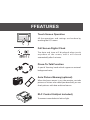
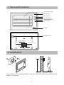
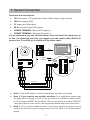
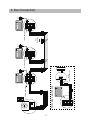
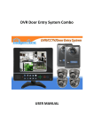
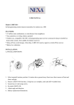
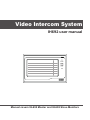
Video Intercom System IH692 user manual CALL UNLOCK TALK/MON IN-USE Manual covers IH-692 Master and IH-692 Slave Monitors PRECAUTIONS ●● Connect this unit ONLY to other compatible units. Do not connect it to any other type of alarm or auxiliary device. Connecting anything else to this unit may damage it or prevent it from operating properly, and will invalidate the warranty. ●● Do not place cables from the AC/DC adapters, camera or monitor where they can be damaged or stepped on. Protect the cables by keeping them out of the way of children, pets and routine household traffic. Do not place heavy objects on power cables; do not cover them with rugs or carpet. ●● Unplug the AC/DC adapters from the wall outlet when the system is not in use for a long time. ●● Slots or openings in the back of the monitor, are provided for ventilation and to ensure reliable operation of the video monitor or equipment and to protect if from overheating. These openings must not be blocked or covered. The monitor should never be placed near or over a radiator and should not be placed in a built-in installation or enclosure unless proper ventilation is provided. ●● All parts should be protected from violent vibration. Impact shocks and dropping may damage the product and should be avoided. ●● Installation of doorbell camera facing into direct sunlight may affect quality of the video. FFEATURES UNLOCK INTERCOM MON/TALK IN-USE Touch Screen Operation All the operations and settings can be done by touching the LCD screen. Full Screen Digital Clock The date and time will displayed when touch anywhere of the screen, and it will closed automatically after 3 minutes. Press-To-Talk Function A special ‘listening’ mode which suppresses external background noise. Auto Picture Memory(optional) When the house owner is out, the monitor can take pictures of visitors who called your door/bell; you can check pictures with date and time later on. RLC Control Unit(not included) To connect second electric lock or light. CONTENT 1. Parts and Functions - - - - - - - - - - - - - - - - - - - - - - - - - - 1 2. Installations- - - - - - - - - - - - - - - - - - - - - - - - - - - - - - - - 1 3. System Connection - - - - - - - - - - - - - - - - - - - - - - - - - - 2 4. Bus Connection - - - - - - - - - - - - - - - - - - - - - - - - - - - - - 3 5. Multi Door Camera Connection - - - - - - - - - - - - - - - - - - 4 6. Basic Video Door Phone Operation - - - - - - - - - - - - - - - 5 7. Operation for Multiple Doorbell Cameras - - - - - - - - - - - 6 8. Intercom Function- - - - - - - - - - - - - - - - - - - - - - - - - - - - 6 9. Ring Tone and Other Settings - - - - - - - - - - - - - - - - - - - 7 10. Picture Memory Operations- - - - - - - - - - - - - - - - - - - - 8 11. Image and Volume Adjustment- - - - - - - - - - - - - - - - - - 9 1. Parts and Functions LCD Touch Screen Microphone CALL button CALL UNLOCK UNLOCK button TALK/MON TALK/MON button IN-USE LED indicator Speaker Ventilation Vent connect slave monitor here connect power here Power Slave Mon CAM 1 connect first camera here Audio H-set connect audio phone here CAM 2 connect second camera here 145~160 cm 2. Installations Use the screws to fix the Mounting Bracket on the wall. Screws and brackets are included with the product for this purpose. -1- 3. System Connection Terminals and descriptions: ●● 1RPower positive. +12V present when Outdoor Station calling or being monitored. ●● 2W Power negative (GND) ●● 3YImage signal (Video signal) ●● 4B Talk and control signal (Audio signal) ●● POWER TERMINAL: Black wire DC negative (-) ●● POWER TERMINAL: White wire DC positive (+) It’s recommended you use shielded alarm cable 4x0.3mm2 for distances up to 30m. For distances over 30m, we suggest you add coaxial cable (RG-59) to connect the 3Y and 2W pin in addition to the alarm cable. UNLOCK INTERCOM MON/TALK 4 * Note 1 2 3 JP-LK Black Yellow Red 1R 2W 3Y 4B White Black Yellow 1R 2W 3Y 4B Red CAM 2 4B 2W +12 Audio H-set 1R 2W 3Y 4B Slave Mon CAM 1 1R 2W 3Y 4B LB 1R 2W 3Y 4B White DC DC+ JP-VD 1 1R 2W 3Y 4B * Note 2 * Note 3 JS-VP AC ~ IN-USE Shielded layer ●● Note 1: Plug the AC Adaptor in to the AC power terminal ensuring it is well seated. ●● Note 2: If you want to use multiple monitors: For a single Monitor system, keep the jumper (which is already on JP-VD ). If you are setting up a multi-Monitor system, remove all JP-VD jumpers EXCEPT the last Monitor. NB If you are setting up monitors PARALLEL rather than chained, the ‘last’ monitor is the one physically furthest away from the door station. ●● Note 3: JP-LK is used to enable the electric Lock function. Remove the jumper if you are going to use the Monitor power to supply power to the Lock. Refer to the Doorbell camera manual. -2- -3- DCDC+ 1R 2W 3Y 4B 4B 2W +12 CN101 CAM 1 CAM 2 1R 2W 3Y 4B Slave Mon 1R 2W 3Y 4B JP-LK JP-VD White Black Red White Black Red GX-3P 4B 2W +12 INSIDE (90 Degree ROTATE) JS-AP JS-LK Audio H-set Back View IN-USE JP-VD Removed! Back View 1R 2W 3Y 4B 1R 2W 3Y 4B JP-LK JP-VD CAM 2 UNLOCK AC ~ CAM 1 MON/TALK 4B 2W +12 1R 2W 3Y 4B IN-USE 4B 2W +12 1R 2W 3Y 4B DC DC+ UNLOCK More Monitors JP-VD Reserved! JP-LK JP-VD Back View 1R 2W 3Y 4B AC ~ 1R 2W 3Y 4B IN-USE MON/TALK INTERCOM Audio H-set INTERCOM CAM 2 1R 2W 3Y 4B DCDC+ UNLOCK Slave Mon Extending Audio Phone: LB Back View CAM 1 1R 2W 3Y 4B JP-LK JP-VD Slave Mon JS-VP JP-VD Removed! CN101 1R 2W 3Y 4B CN101 Black MON/TALK CAM 2 Red CAM 1 White 4B 2W +12 1R 2W 3Y 4B DC DC+ UNLOCK IN-USE MON/TALK INTERCOM Slave Mon Yellow CN101 1 2 3 INTERCOM AC ~ 4. Bus Connection Audio H-set Audio H-set JS-VP 1R 2W 3Y 4B Black LB 2# Camera Red -4- JS-VP LB JP-VD Removed! 1R 2W 3Y 4B 1R 2W 3Y 4B JP-LK JP-VD Back View CAM 1 White DC DC+ UNLOCK IN-USE MON/TALK INTERCOM AC ~ JP-VD Removed! 1R 2W 3Y 4B 1R 2W 3Y 4B JP-LK JP-VD Back View CAM 2 Audio H-set 4B 2W +12 1R 2W 3Y 4B DC DC+ UNLOCK IN-USE MON/TALK INTERCOM AC ~ More Monitors JP-VD Reserved! NOTE: When connect two Outdoor Stations, one/two camera Mode should be set to 2 on the 1# Monitor. (Menu-setup-installation-one/two camera) 4B 2W +12 1R 2W 3Y 4B Slave Mon Yellow CAM 1 1R 2W 3Y 4B CN101 Audio H-set Red CN101 Black Slave Mon White 1R 2W 3Y 4B 1R 2W 3Y 4B JP-LK JP-VD Back View CAM 1 Yellow 4B 2W +12 1R 2W 3Y 4B DC DC+ UNLOCK IN-USE MON/TALK INTERCOM Slave Mon 1 2 3 CN101 1 2 3 1# Camera AC ~ 5. Multi Door Camera Connection Audio H-set CAM 2 CAM 2 6. Basic Video Door Phone Operation 1. When a visitor presses the Call button on the doorbell/camera unit, the monitor will ring and display the visitor’s image; also the IN-USE LED will turn red. TALK EXIT rec 2. To answer the doorbell, press the TALK/MON 03 button (or touch TALK icon on the screen). You can talk with the visitor for 90 seconds before the screen will automatically shut off. To end the Intelligent Home S y s t e m conversation yourself, press TALK/MON Button (or touch TALK icon) again. If nobody responds to the visitor, the monitor will turn off automatically after 30 seconds 3. Press-To-Talk: The monitor has a special ‘listening’ mode which suppresses external background noise and makes it easier for you to hear the person at the door. When the mornal Press to talk EXIT rec 03 talk is started, press to enter PressTo-Talk state, and you will in Listening state Press to talk by default, press / to toggle between Speaking state and Listening state. Press Auto Talk to exit Press-To-Talk state and return to normal talking state. Intelligent Home S y s t e m IMG 16 Auto Talk 4. When Monitor is in standby, press TALK/MON button (or touch anywhere on the screen, then touch monitor ) and the screen will display the view from the doorbell (Outdoor Station). During monitoring state, press TALK/MON button (or EXIT rec 03 2009/02/14 10:30 Intelligent Home S y s t e m touch TALK icon) to talk to someone outside. Press again to exit. Monitoring state is limited to 30 seconds and will shut off automatically. 5. When you wish to open the door lock, press UNLOCK button (or touch Electric Lock. icon) to release the 6. To get the system to record pictures automatically from the doorbell when people come to the door, press MENU, press SETUP and press AUTO-RECORD on. It will record up to 120 pictures of people at the door even if you are not there to answer. 7. Touch the icon to hide the icons; to re-show the icons, touch anywhere on the screen again. 8. Press the CALL Button (or touch rec icon) to manually record the current picture. -5- 7. Operation for Multiple Doorbell Cameras 1. If two doorbell cameras are required, the One/Two Camera option should be enabled. To do this, touch setup icon to enter SETUP. Now press ADVANCED SET (tings) submenu. Enter the password (2008), and change the mode to 1/2 CAMERA. 2. Two doorbell cameras can be connected to the monitor directly. The second outdoor station can be a doorbell or a CCTV camera. For the system to function correctly, you must have at least one doorbell. If there is only one Outdoor station to be installed, the Outdoor station must be connected to the CAM1 Port. The second must be connected to the CAM2 Port. 3. When monitoring multiple doorbells/CCTV cameras (outdoor stations), switch between them by pressing TALK/MON. Each time you press TALK/MON it will take you to the next outdoor station. 4. Please Note: If two doorbells connected, and each doorbell is connected to an electric lock, when you operate EITHER of the UNLOCK buttons on EITHER monitor, it will unlock BOTH locks. If you don’t wish for this to happen, you can purchase and install an RLC controller and operate them separately 8. Intercom Function 1. Intercom can be initiated by either Monitor. Press the INTERCOM button, the other Monitor will ring. Press TALK/MON button on the other Monitor to answer. 2. To end the intercom conversation, press TALK/ MON. If no one answers, it will exit automatically after 30 seconds. 3. The doorbell function will always override the intercom function. -6- Redial EXIT Intelligent Home S y s t e m 9. Ring Tone and Other Settings 1. Touch anywhere on the screen and the date/time page will be displayed. The first line shows the current time, the second line shows the current date and weekday. The date/time page will close in 3 minutes if no buttons are pressed. 2. Entering the main Menu: Touch the screen again to enter the Main Menu, press enter Setup Menu. setup Intelligent Home S y s t e m icon to play 3. Outdoor Tone and Intercom Tone are for choosing the doorbell melody and the intercom melody. Touch value / monitor intercom setup to increase/decrease the exit Intelligent Home S y s t e m 4. Monitor Time: To change the amount of time the monitor will remain active if no buttons are pressed, use the plus and minus buttons to set between 30 seconds and 10 minutes. 5. Auto Record: If the item is set to ON(the LED will flashes green), the Monitor will record the image automatically in 2 seconds after the visitor pressed the CALL Button on the Outdoor station(the LED turn to red if there is a missing call picture). 6. Advanced Set: To access the Advanced Settings, a password will be required before entering. The default password is 2008 7. Input the password by touching the digital keypad on the screen to enter. 8. The 1/2 Camera can be set to 2 if two outdoor stations are to be installed. 9. Unlock Time: can be adjusted according to different locks. Outdoor Tone -- 01 Intercom Tone -- 05 Monitor Time -- 1min Advanced Set... Auto Record -- OFF Exit Intelligent Home S y s t e m Password: 0 *** * Intelligent Home S y s t e m One/Two Camera -- 1 Unlock Time -- 3 Date/Time Set... Other Device Set... Information... Exit Intelligent Home S y s t e m -7- 1 2 3 4 5 6 7 8 9 0 # 10. Date/Time Set: to amend the time and date, access this option. Use MENU button to move the cursor, and plus minus buttons to change the date/ time. Touch the ‘#’ icon (on the number key pad) to save and exit or touch the''icon to cancel Time 1 1 : 3 5 Date 2 0 0 9 0 2 1 4 #: OK * : Cancel 1 2 3 4 5 * 6 7 8 9 0 # Intelligent Home S y s t e m 11. Other Device Set: submenu: RLC and Remote settings. 12. Information: submenu: shows the hardware/ software version and voltage info. Press Restore to Default if you wish to restore all the settings to factory defaults. Hardware ver A1.1 Software ver A6.1 Voltage 16.2V Manufacture D1.2 Restore to default Exit Intelligent Home S y s t e m 10. Picture Memory Operations 1. Pictures can be recorded both manually and automatically. Image capacity is about 128 pictures. When the memory is full, the oldest picture will be replaced. play monitor intercom 2. Manually taking pictures: If you wish to take a picture, you can do so by pressing MONITOR, then pressing the REC icon setup exit rec .. Intelligent Home S y s t e m 3. Automatic recording: (see instructions above to enable this option) 4. Note: Indicator light flashing green - image recorder "ON" and ready; Indicator light steady red - image recorder has new images waiting to be viewed; Indicator light steady green - image recorder "OFF" . 5. Viewing pictures: To view the pictures on your monitor, press the PLAY button. The latest pictures will be shown. To move through the pictures, press either the PLAY button (or touch the play IMG 16 DELETE? LAST DELE? icon). To delete a picture, touch the DELE? icon. A 'DELETE?' hint will show on the upper right of the screen. Touch the DELE? icon again to delete the current picture. Please note that deleted pictures cannot be restored. -8- NEXT EXIT Intelligent Home S y s t e m 11. Image and Volume Adjustment 1. During monitoring or talking, press MENU will be displayed. icon, ADJUST TALK 2. Touch the + / - icons to increase or decrease current value; touch the adjustment item. EXIT icon to switch to the next 3. The first item is Scene mode selection: Total 4 SCREEN modes can be selected in sequence: NORMAL, USER, SOFT and BRIGHT. Whenever you modify BRIGHTNESS or COLOUR, SCENE item will be set to USER mode automatically. rec 03 Intelligent Home S y s t e m soft Scene 4. RATIO can be shifted from 16:9 to 4:3. 5. The Brightness and Color item is for image quality setting. Adjust the value to get the best image. + — Intelligent Home S y s t e m 6. The Ring Volume and Talk Volume items are for ring tone and talking volume adjustment 7. Note that all the modifications will be done immediately after the operation. Touch the exit out the setting. icon to 12. Specifications ●● Power supply for indoor monitor: DC 15~18V (supplied by Adaptor) ●● Power supply for Door Station: DC 10~12V (Supplied by Monitor) ●● Power consumption: Standby 0.5W; Working status 15W (for kits) ●● Monitor screen: 7 Inch color TFT-LCD ●● Display Resolutions: 1,440(R, G, B) x 234 pixels ●● Video signal: 1Vp-p, 75Ω, CCIR standard ●● Picture Memo Capacity: 127 PCS ●● Monitor time: 30 seconds ●● Talking time: 90 seconds ●● Dimensions: 155(H)×225(W)×28(D)mm -9- WARRANTY CARD NB Please keep this document safe, as it is proof of your Warranty Your Video door system comes with a one year Manufacturers Warranty. When used normally, the following services are offered: 1. Replacement for malfunctioning parts in first three months 2. Repair free of charge for malfunctioning parts in first year The following actions will void the Warranty: 1. Damage to the device during installation 2. Damage to the device through misuse 3. Opening and/or disassembling the device 4. Attempting to force the device to perform functions for which it is not intended 5. Attaching the device to power supplies other than thoserecommended by the manufacturer Distributor for Warranty purposes: Intelligent Home Online Ltd 34a High Street Hornsey London N8 7NX +44 (0)20 83482040 www.intelligenthomeonline.com Product:_____________________________________________ Purchaser Name: ______________________________________ Invoice N: ____________________________________________ Purchase Date_________________________________________ -10- The design and specifications can be changed without notice to the user. Right to interpret and copyright of this manual are preserved. ST-ENG-IH692MT-V2.2 101S101