1
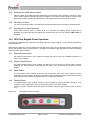
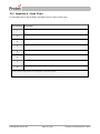
3500 CONVENTIONAL FIRE ALARM CONTROL PANEL USER MANUAL Protec Fire Detection PLC, Protec House, Churchill Way, Nelson, Lancashire, BB9 6RT. Telephone: Fax: Web: Email: +44 (0) 1282 717171 +44 (0) 1282 717273 www.protec.co.uk [email protected] Document Revision Details Issue Issue 0 Issue 1 Issue 2 Modification Detail Document Creation Refer to ECN3504 Refer to ECN3715 N 93-585-83 Issue 2 AB Author AB AB AB Page 2 of 25 Date 22/11/2013 14/05/2014 07/04/2015 © Protec Fire Detection PLC 2015 Table of Contents 1.0 INTRODUCTION ..................................................................................................................................... 5 2.0 USER RESPONSIBILITIES .................................................................................................................... 6 2.1 3.0 ROUTINE TESTING OF THE SYSTEM .................................................................................................. 7 3.1 3.2 3.3 3.4 3.5 3.6 4.0 General Fire Indicator Illuminated ............................................................................................... 10 Zone Fire Indicator Illuminated.................................................................................................... 10 3500 FAULT INDICATIONS ..................................................................................................................10 7.1 7.2 7.3 7.4 7.5 8.0 General Indications ....................................................................................................................... 9 Multifunction Zone Status Indications ........................................................................................... 9 Code Entry and Menu Keys .......................................................................................................... 9 Sound Alarms, Silence Alarms, Reset Panel and Mute Buzzer keys ........................................... 9 3500 FIRE INDICATIONS .....................................................................................................................10 6.1 6.2 7.0 Access Level 1 (General User) ..................................................................................................... 8 Access Level 2 (Authorised person appointed by the premises management) ............................ 8 3500 INDICATIONS AND CONTROLS .................................................................................................. 9 5.1 5.2 5.3 5.4 6.0 Daily Inspection ............................................................................................................................. 7 Weekly Test................................................................................................................................... 7 Monthly Test .................................................................................................................................. 7 Quarterly Test................................................................................................................................ 7 Annual Test ................................................................................................................................... 7 5 Yearly Test ................................................................................................................................. 7 3500 ACCESS LEVELS .......................................................................................................................... 8 4.1 4.2 5.0 Requirements of the Premises Management Named Person ...................................................... 6 Zone Faults ................................................................................................................................. 10 System Faults.............................................................................................................................. 10 Alarm Fault .................................................................................................................................. 10 Supply Fault ................................................................................................................................ 11 Aux Supply Fault ......................................................................................................................... 11 3500 DISABLEMENT INDICATIONS ...................................................................................................11 8.1 8.2 Zone Disablement ....................................................................................................................... 11 Alarm Disablement ...................................................................................................................... 11 9.0 3500 TEST INDICATIONS ....................................................................................................................11 10.0 MISCELLANEOUS INDICATIONS .......................................................................................................11 10.1 10.2 10.3 Power on Indication ..................................................................................................................... 11 Outputs Delayed Indication ......................................................................................................... 11 Access Level Indication ............................................................................................................... 11 11.0 SYSTEM DELAYS.................................................................................................................................12 12.0 COINCIDENCE OPERATION ...............................................................................................................12 13.0 3500 RESPONSE TO AN ALARM ........................................................................................................12 13.1 13.2 13.3 13.4 13.5 13.6 13.7 14.0 Automatic Detection .................................................................................................................... 12 Manual Detection ........................................................................................................................ 12 Coincidence Activation ................................................................................................................ 12 Silencing the Alarms ................................................................................................................... 12 Resetting the 3500 after an Alarm .............................................................................................. 13 New Zone in Alarm ...................................................................................................................... 13 Activating the Alarms Manually ................................................................................................... 13 3500 FIRE BRIGADE PANEL OPERATION ........................................................................................13 14.1 Silence Buzzer Button ................................................................................................................. 13 N 93-585-83 Issue 2 AB Page 3 of 25 © Protec Fire Detection PLC 2015 14.2 14.3 14.4 15.0 Silence Alarms Button ................................................................................................................. 13 Reset Button................................................................................................................................ 13 Disable Button ............................................................................................................................. 13 3500 ACCESS LEVEL 2 USER OPTIONS ...........................................................................................14 15.1 15.2 15.3 15.4 Programming Zone and Alarm Disablements ............................................................................. 14 Enabling Weekly Test Mode ....................................................................................................... 14 Testing the Panel Indications and Internal Buzzer...................................................................... 15 Clearing System Faults ............................................................................................................... 15 16.0 APPENDIX 1 - 3500 SYSTEM SET UP RECORD ................................................................................16 17.0 APPENDIX 2 - 3500 FIRE AND FAULT EVENT LOG .........................................................................18 18.0 APPENDIX 3 – 3500 OPERATION QUICK REFERENCE GUIDE ......................................................23 18.1 18.2 18.3 18.4 18.5 18.6 18.7 18.8 19.0 Entering Access Level 2 .............................................................................................................. 23 Returning to Access Level 1 ....................................................................................................... 23 Testing the Front Panel Indicators and Internal Buzzer .............................................................. 23 Performing a Weekly Test ........................................................................................................... 23 Muting the Internal Buzzer and accepting Current Faults ........................................................... 23 Sounding the Alarms ................................................................................................................... 23 Silencing the Alarms ................................................................................................................... 23 Resetting after an alarm .............................................................................................................. 23 APPENDIX 4 - ZONE CHART ...............................................................................................................24 N 93-585-83 Issue 2 AB Page 4 of 25 © Protec Fire Detection PLC 2015 1.0 Introduction The 3500 is a conventional fire alarm control panel available in 2, 4 and 8 zone models. The 3500 incorporates all detection zone circuits, an integrated power supply and two fully monitored alarm circuits. The 3500 includes many programming and configuration features making it easy to integrate to a variety of site conditions. The 3500 is primarily designed to drive Protec 3000PLUS detection devices. The 3500 has been designed and manufactured in the United Kingdom and complies fully with current standards dictating fire alarm system design practice (EN54 parts 2 and 4). The integrity and reliability of a fire alarm system is paramount and consequently the 3500 continually monitors all critical paths for faults. The fire detection zones and wiring are constantly monitored to check for faults. The integrated power supply regularly performs self-checks to ensure it is fully working and that the stand-by batteries are in a good state. Any alarms or faults detected are reported clearly on the front panel display A system set up sheet (see appendix 1) must be completed by the commissioning engineer prior to handing the system over to the customer. The system set up sheet details exactly how the system has been configured and programmed by the commissioning engineer and, being the only such record, should be kept in a safe place. The fire alarm event log (see appendix 2) must be completed by the authorised user of the system every time a 3500 fire or fault event occurs. It is advisable to make copies of the blank event log to allow the log to be continued when the sheets included have been used. . There are no user serviceable parts inside the 3500. A competent person trained to undertake such work MUST carry out any internal maintenance work. A separate installation and commissioning manual is available. The policy of Protec Fire Detection plc is one of continuous improvement and as such we reserve the right to make changes to product specifications at any time and without prior notice. Errors and omissions excepted. N 93-585-83 Issue 2 AB Page 5 of 25 © Protec Fire Detection PLC 2015 2.0 User Responsibilities The registered owner of the fire alarm system has specific responsibilities regarding the installation, testing and maintenance of the fire alarm system. BS5839 part 1: 2013 Section 7 states that the user of the fire alarm system must appoint a single named person to supervise all matters regarding the fire alarm system. Summarised below are the responsibilities expected of the named person, It is strongly advised that a full copy of BS5839 part 1: 2013 is obtained and thoroughly read and understood. 2.1 Requirements of the Premises Management Named Person Ensure that the fire alarm equipment is checked at least once every 24 hours to ensure there are no faults on the system. Report any faults to the site maintenance manager. Ensure that arrangements are in place for correct testing of the fire alarm system (as specified in BS5839 part 1: 2013 Section 6, summarised in section 3.0 of this document). Ensure that the system event log is kept up to date and is available for inspection by any authorised person when required. An example event log is included in appendix 2 of this document. Ensure that all occupants of the protected premises are trained how to use the system properly and that they are aware of what action to take in the event of an alarm. Ensure that false alarms are minimised. Ensure all detectors and manual call points are not obstructed. Detectors must have at least 500mm clear space preserved in all directions around them. Establish a liaison with those responsible for changes in, or maintenance of the building fabric. Ensure that when changes are made to the system, record drawings and operating instructions are updated. Ensure that, where necessary, a suitable zone plan is displayed and kept up to date. Ensure that any relevant spare parts for system maintenance are held within the premises. N 93-585-83 Issue 2 AB Page 6 of 25 © Protec Fire Detection PLC 2015 3.0 Routine Testing of the System Recommendations for testing of the system are fully detailed in section 6 of BS5839 part 1: 2013. 3.1 3.2 Daily Inspection Check that the green Supply Present indicator is illuminated Check for any faults on the system and report these to the site maintenance manager Weekly Test Perform the daily tests recommended in 3.1 and; Perform an indicator test (lamp test) to check the integrity of the front panel indications and internal buzzer Ensure no Manual Call Points or detectors are obstructed During the test you may wish to place the 3500 into weekly test mode (consult section 13.3) 3.3 Operate a Manual Call Point or detector during normal working hours to ensure the fire alarm system operates correctly A different Manual Call Point or detector on a different zone should be tested each week, in this way all the devices on all the zones are eventually tested Ensure the system sounders are operational Ensure the sounders are not operated for longer than 30 seconds during testing. The occupants of the building can then distinguish genuine alarms Monthly Test Perform the weekly test recommended in 3.2 and; 3.4 If an automatic generator is used as part of the mains failure back-up system it should be started up once each month by simulated failure of the normal power supply, and then run in this mode for at least 1 hour Visually inspect the stand-by batteries and their connections. Check that the batteries are capable of supplying the alarm sounders Quarterly Test Perform the monthly test recommended in 3.3 and; 3.5 Ensure the system event log is up to date and all entries are correct. Check that any faults noted have been rectified Annual Test Perform the quarterly test recommended in 3.4 and; 3.6 Test every smoke and heat detector, Manual Call Point and all auxiliary equipment for correct functionality 5 Yearly Test Perform the Annual test recommended in 3.5 and; Carry out a full wiring check in accordance with the testing and inspection requirements of the relevant National wiring regulations (I.E.E regulations for the UK). N 93-585-83 Issue 2 AB Page 7 of 25 © Protec Fire Detection PLC 2015 4.0 3500 Access Levels The 3500 has two access levels to allow users of different authorisation levels access to various parts of the system. The access levels and a description of functions available are given in the next sections. 4.1 Access Level 1 (General User) Access level 1 allows the general user to view the status of the 3500 at any time. Zone fire, fault, disablement and test states are clearly displayed as are any current system faults, disablements or delays. Full detail of the front panel display is given in section 5.0. The following functions may be performed at access level 1. 4.2 Entry of the 6 digit user code to access level 2 or level 3 functions Activation of the front panel fireman's key-switch (correct model must be ordered) Access Level 2 (Authorised person appointed by the premises management) Access level 2 allows the authorised user access to various critical system functions. To enter access level 2 either enter the user code using the numbered keypad or insert and turn the fire man’s key-switch (depending on the particular model purchased). When access level 2 has been entered the 'Access Level' indicator will illuminate and access level 2 menus are available. To return to access level 1 press the ‘’ key. As a security measure the 3500 will return to access level 1 if no key activity has been detected for 30 minutes. The following functions are available at access level 2. Accepting the current state of the panel and Mute the panel’s internal buzzer Silencing an alarm condition Resetting the panel after silencing an alarm activation Sounding the alarms Disablement of detector circuits Disablement of alarm circuits Programming weekly test mode (all zones in walk test mode) Testing the front panel indications and internal buzzer Clearing of system faults N 93-585-83 Issue 2 AB Page 8 of 25 © Protec Fire Detection PLC 2015 5.0 3500 Indications and Controls The 3500 has a comprehensive front panel display enabling the current state of the 3500 to be rapidly determined. Figure 5.0 shows the indications and controls. Figure 5.0 3500 front panel indications and controls. Row 1 Row 2 Keypad Column 1 5.1 Column 2 General Indications Row 1 comprises the General Fire, Fault, Disablement and Test indicators. These indications give clear indication that the 3500 has at least one Fire, Fault, Disablement or Test condition. 5.2 Multifunction Zone Status Indications Zone status indicators are located in row 2 and contain zone pairs, one indicator for fault, disablement, test and the other indicator for fire. Zone fires are indicated when the zone indicator flashes red, and are always accompanied by the General Fire indicator. Zone faults are indicated when the zone indicator flashes yellow and are always accompanied by the General Fault indicator. Zone disablements are indicated when the zone indicator lights steady yellow and are always accompanied by the General Disablement indicator. Zones in test mode are indicated when the zone indicator lights steady yellow and are always accompanied by the General Test indicator. 5.3 Code Entry and Menu Keys The keys in the centre of the 3500 are used to enter the user code (using keys 1, 2, 3 and 4) and are also used to navigate the menu system. 5.4 Sound Alarms, Silence Alarms, Reset Panel and Mute Buzzer keys These keys are used to control panel functions. The user code must be entered before the keys become operational. N 93-585-83 Issue 2 AB Page 9 of 25 © Protec Fire Detection PLC 2015 6.0 3500 Fire Indications The 3500 displays fire information by illuminating the General Fire indicator and the relevant red zone indicators. The following sections detail the meaning of each indicator. 6.1 General Fire Indicator Illuminated The 3500 has detected a fire on one of its zones. The building fire plan should be executed immediately 6.2 Zone Fire Indicator Illuminated The 3500 has detected a fire in the indicated zone. The General Fire indicator will always accompany this and the internal buzzer will be fast pulsing. 7.0 3500 Fault Indications When the 3500 has detected a fault in any of the critical operating paths of the system it will display this on the front panel display. The internal buzzer will also pulse slowly. The General Fault indicator will be illuminated and is always accompanied by other indicator(s) detailing the exact fault. By pressing the Mute Buzzer button in access level 2 the fault is accepted and the internal buzzer will be muted. Further faults reactivate the buzzer. In the event of any fault the following action should be taken: Investigate the fault, then, at access level 2, accept the fault by pressing the Mute Buzzer button. Note the fault down in the Logbook and take action to remedy the fault. In all cases expert advice must be sought When the fault has been rectified the fault indicator will automatically extinguish. The following sections give descriptions of each fault. 7.1 Zone Faults The 3500 displays any faults in the detection zones on the zone indicators. The ‘General Fault’ indicator will be illuminated accompanied by the relevant zone fault indicator flashing. Pressing Mute Buzzer will mute the buzzer. 7.2 System Faults The 3500 performs regular self tests to ensure the software is working correctly. If a fault is detected in software operation the ‘System Fault’ indicator will illuminate. This is a latching fault and can only be cleared by using the ‘Clear System Faults’ option. 7.3 Alarm Fault The 3500 performs checks on the alarm outputs and if a fault has been detected on one or more of the alarm outputs the ‘General Fault’ indicator will be illuminated accompanied by the ‘Alarm Fault’ indicator. Devices connected to the alarm outputs may no longer operate correctly. N 93-585-83 Issue 2 AB Page 10 of 25 © Protec Fire Detection PLC 2015 7.4 Supply Fault The 3500 regularly check the internal power supply. If a fault has been detected in the power supply of the 3500 the ‘General Fault’ indicator will be illuminated accompanied by the ‘Power Fault’ indicator. This may be due to local mains supply failure or because the internal stand-by batteries or circuitry are faulty. 7.5 Aux Supply Fault The 3500 monitors the state out the aux supply output and if a fault has been detected the ‘General Fault’ indicator will be illuminated accompanied by the ‘Aux Supply Fault’ indicator. There may no longer be an auxiliary supply to external devices or the auxiliary devices are drawing too much current. 8.0 3500 Disablement Indications 8.1 Zone Disablement The 3500 displays any disablements of the detection zones on the zone indicators. The ‘General Disablement’ indicator will be illuminated accompanied by the relevant zone indicator Fires and faults are prevented from a disabled zone. Detectors and Manual Call Points in this zone will not trigger the 3500 into a fire condition. 8.2 Alarm Disablement The 3500 illuminates the ‘General Disablement’ indicator accompanied by the 'Alarms Disabled' indicator. Activation to and faults from alarm outputs are prevented. Sounders will not operate in the event of a fire. 9.0 3500 Test Indications If any of the 3500 zones are in test mode the ‘General Test’ indicator will be illuminated accompanied by the relevant zone indicator illuminated steady yellow. 10.0 Miscellaneous Indications 10.1 Power on Indication This indication illuminates when the 3500 is powered up from mains or its internal batteries. 10.2 Outputs Delayed Indication This indicator will be illuminated if the commissioning engineer has programmed a delay to the alarm outputs. The alarms may not activate immediately in the event of a fire. 10.3 Access Level Indication If the 3500 panel is in access level 2 then the ‘Access Level’ will be illuminated. If the 3500 panel is in access level 3 then the ‘Access Level’ will be flashing. N 93-585-83 Issue 2 AB Page 11 of 25 © Protec Fire Detection PLC 2015 11.0 System Delays Delays may have been programmed into the 3500 at commissioning time to allow a predetermined delay time from zone activation until the alarm outputs activate. Delays may be used in order to allow time for the cause of the activation to be investigated by a responsible person. If the cause of the activation is found to be legitimate the alarm outputs can be manually activated. If the cause of the activation is found to be false the 3500 can be reset. The 3500 system set-up chart must be consulted to determine exactly which outputs have been delayed and how the delay time has been set up. If the Silence Alarms button is pressed while a delay is running, the alarm outputs will not be activated when the delay expires. Delays only apply to automatic detector activations. A manual activation on a zone (activating a Manual Call Point) overrides all current delays. 12.0 Coincidence Operation At the time of commissioning, the system may have been programmed to operate in ‘coincidence’ mode. Coincidence operation is used in order to minimise the effects of false alarms. Coincidence operation can be used to prevent alarm outputs in certain areas from triggering until two or more zones have been activated. This allows the initial activation to be investigated before the alarm outputs of the 3500 are activated. 13.0 3500 Response to an Alarm 13.1 Automatic Detection If an automatic detector (smoke, heat etc) activates on a zone of the 3500 this is known as an automatic operation. The 3500 responds by; 13.2 Illuminating the ‘General Fire’ indicator Flashing the relevant zone fire indicator Fast pulsing of the internal buzzer Activating alarm outputs as programmed, after any delays have expired. Activating the Global Fire contacts. Manual Detection If a Manual Call Point is operated on the zone of a 3500 this is known as manual operation. The 3500 responds by; 13.3 Illuminating the ‘General Fire’ indicator Flashing the relevant zone fire indicator Fast pulsing of the internal buzzer Immediately activating alarm outputs as programmed (any programmed delays are overridden) Activating the Global Fire contacts Coincidence Activation Please see section 12.0 13.4 Silencing the Alarms Pressing Silence Alarms when in access level 2 will silence alarm outputs. A further activation will re-sound the alarms. N 93-585-83 Issue 2 AB Page 12 of 25 © Protec Fire Detection PLC 2015 13.5 Resetting the 3500 after an Alarm After the cause of the alarm has been determined (and entered in the fire alarm log book) the 3500 can be reset if required. Manual Call Points, if triggered, must first be reset locally. In access level 2 press ‘Silence Alarms’ then press ‘Reset Panel’. The 3500 will reset any devices on its zones. 13.6 New Zone in Alarm If a new zone goes into alarm, the 3500 will re-activate the alarms and re-sound the internal buzzer. 13.7 Activating the Alarms Manually Press ‘Sound Alarms’ when in access level 2 to evacuate the building. Alarm outputs will be activated as programmed but the Global Fire Contacts and the Fire Link Interface WILL NOT be activated. 14.0 3500 Fire Brigade Panel Operation If the 3500 is equipped with the optional fire brigade controller, shown in figure 14.0, the following operations can be carried out. Whilst the key-switch is in the off position the controller will not carry out any functions and the operated LED will be extinguished. When the key-switch is activated the operated LED will illuminate and the following button functions will be enabled. 14.1 Silence Buzzer Button The silence buzzer button, when enabled, will allow the user to silence the audible indication of a fault or a fire condition. 14.2 Silence Alarms Button The silence alarms button, when enabled, will allow the user to silence any active alarms outputs. Following the alarms outputs being silenced this button can be pressed to resound the alarm outputs. 14.3 Reset Button The reset button, when enabled, allows the user to reset the panel from a fire condition. A panel reset will only occur following a silence of the alarm outputs and should only be reset after the cause of the alarm has been determined (and entered in the fire alarm log book). 14.4 Disable Button The disable button, when enabled, allows the user to disable any zones that are currently in a fire condition. A zone disable will only occur following a silence of the alarm outputs. Following a panel reset the zones will require re-enabling using the panel menus (refer to section 15.1) Figure 14.0 Fire Brigade Panel Controller N 93-585-83 Issue 2 AB Page 13 of 25 © Protec Fire Detection PLC 2015 15.0 3500 Access Level 2 User Options 15.1 Programming Zone and Alarm Disablements This menu allows the user to disable any or all of the detection zones and/or both of the alarm circuits (activations and faults are inhibited when the circuit is disabled). Sequence Effect Enter the access level 2 code 'Access Level' indicator illuminates steady Press button '1' to enter the disablement menu 'Disablement' indicator flashes Zone 1 indicator flashes Any currently disabled zones or alarms illuminate steady Press button '2' or '3' to cycle round disablement choices Cycles through disablement choices, selected choice flashes the relevant indicator. Choices are: Individual zones -> all zones -> alarms Press button '1' to disable current choice Relevant indicator changes to steady Press button '4' to enable current choice Relevant indicator turns off Press 'Enter' button to save and exit Saves current settings into memory and exits the menu 15.2 Enabling Weekly Test Mode The 3500 allows all zones to be programmed into weekly test mode, this permits rapid verification of device operation on zones. In this mode, activations from zones sound the alarms for 10 seconds for verification purposes, after which the 3500 automatically resets and exits weekly test mode. If no zone activations are detected for 10 minutes, weekly test mode is automatically exited. Sequence Effect Enter the access level 2 code 'Access Level' indicator illuminates steady Press button '2' to activate weekly test mode Activates weekly test mode ‘Test’ indicator illuminates Zone test indicators illuminate Press button '2' to exit weekly test mode Exits weekly test mode ‘Test’ indicator extinguishes Zone test indicators extinguish N 93-585-83 Issue 2 AB Page 14 of 25 © Protec Fire Detection PLC 2015 15.3 Testing the Panel Indications and Internal Buzzer The 3500 allows the front panel indications and internal buzzer to be tested. In this mode all indicators are momentarily illuminated and the internal buzzer sounded. If any indicators fail to illuminate, or the buzzer does not sound, note this in the system log and get the fault rectified immediately. Sequence Effect Enter the access level 2 code 'Access Level' indicator illuminates steady Press button '3' to activate the lamp and buzzer test All indicators momentarily illuminate and the internal buzzer sounds 15.4 Clearing System Faults In general faults on the 3500 are non-latching and will clear automatically when the fault is rectified. Some faults however are latched on the system and require clearing manually. Sequence Effect Enter the access level 2 code 'Access Level' indicator illuminates steady Press button '4' to clear any latched faults Any latched faults are cleared. If the fault remains it will be re-generated. N 93-585-83 Issue 2 AB Page 15 of 25 © Protec Fire Detection PLC 2015 16.0 Appendix 1 - 3500 System Set up Record The engineer in charge of commissioning the system must complete this sheet. It is the only record of how the system has been configured and, as such, must be safely stored for future reference. COMMISSIONING DETAILS System Commissioned By Date System Commissioned Company Contact Details Authorised User Code CONNECTION 1 3 4 CONNECTED TO / PROGRAMMING 4 2 2 RESULT Global Fault Global Fire Class Change Auxiliary 24V Notes: N 93-585-83 Issue 2 AB Page 16 of 25 © Protec Fire Detection PLC 2015 ZONE ZONE DESCRIPTION / LOCATION / COMMENTS PROGRAMMING 1 2 3 4 5 6 7 8 N 93-585-83 Issue 2 AB Page 17 of 25 © Protec Fire Detection PLC 2015 17.0 Appendix 2 - 3500 Fire and Fault Event Log The person appointed in charge of the fire alarm system must complete the relevant section of this sheet whenever a fire or fault event occurs on the system. Name of appointed responsible person …………………………………………………………………………………………………... Contact details of above person …………………………………………………………………………………………………... Contact details of maintenance person / company ………………………………………………………………………………………………………..…. ……………………………………………………………………………………………………..……. …………………………………………………………………………………………………………… …………………………………………………………………………………………………………… N 93-585-83 Issue 2 AB Page 18 of 25 © Protec Fire Detection PLC 2015 3500 Fire Alarm System Event Log DATE TIME ZONE N 93-585-83 Issue 2 AB DETAILS ACTION REQUIRED Page 19 of 25 COMPLETED NAME © Protec Fire Detection PLC 2015 DATE TIME ZONE N 93-585-83 Issue 2 AB DETAILS ACTION REQUIRED Page 20 of 25 COMPLETED NAME © Protec Fire Detection PLC 2015 DATE TIME ZONE N 93-585-83 Issue 2 AB DETAILS ACTION REQUIRED Page 21 of 25 COMPLETED NAME © Protec Fire Detection PLC 2015 DATE TIME ZONE N 93-585-83 Issue 2 AB DETAILS ACTION REQUIRED Page 22 of 25 COMPLETED NAME © Protec Fire Detection PLC 2015 18.0 Appendix 3 – 3500 Operation Quick Reference Guide 18.1 Entering Access Level 2 Using the keypad enter the user code (supplied with the control panel’s documentation), or turn the key-switch (depending on the model purchased). 18.2 Returning to Access Level 1 Press the ‘’ key. 18.3 Testing the Front Panel Indicators and Internal Buzzer From access level 2, press button '3' to activate lamp test mode. Check all indicators illuminate and the internal buzzer sounds. 18.4 Performing a Weekly Test From access level 2 press button '2' to activate weekly test mode. Test a device on the relevant zone. The alarms will sound for 10 seconds, then the 3500 will automatically reset and exit test mode. 18.5 Muting the Internal Buzzer and accepting Current Faults From access level 2 press the 'Mute Buzzer' button. 18.6 Sounding the Alarms From access level 2 press the 'Sound Alarms' button. 18.7 Silencing the Alarms From access level 2 press the 'Silence Alarms' button. A further activation will re-sound the alarms. 18.8 Resetting after an alarm Determine the cause of the alarm before resetting the panel Ensure the cause of the alarm has been removed, and any Manual Call Points locally reset. From access level 2 press the 'Silence Alarms' button then press the 'Reset Panel' button. N 93-585-83 Issue 2 AB Page 23 of 25 © Protec Fire Detection PLC 2015 19.0 Appendix 4 - Zone Chart It is intended that this chart be filled in and affixed near the 3500 control panel. Zone Number Description 1 2 3 4 5 6 7 8 Details of person responsible for management of fire alarm system N 93-585-83 Issue 2 AB Page 24 of 25 © Protec Fire Detection PLC 2015 Protec Fire Detection PLC, Protec House, Churchill Way, Nelson, Lancashire, BB9 6RT. Telephone: Fax: Web: Email: +44 (0) 1282 717171 +44 (0) 1282 717273 www.protec.co.uk [email protected] N 93-585-83 Issue 2 AB Page 25 of 25 © Protec Fire Detection PLC 2015