1
FT-817
OPERATING MANUAL
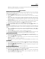
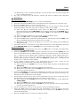
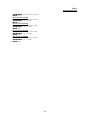
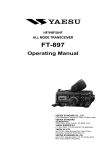
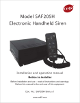
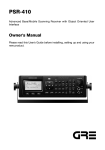
Front Panel Control & Switches
(1) PWR Switch
Press and hold in the PWR switch for one second to turn to the transceiver on or off.
(2) AF Knob
This (inner) VOL knob adjusts the receiver audio volume level presented to the speaker
or external speaker. Clockwise rotation increases the volume level.
(3) SQL/RF Knob
In the USA version, this (outer) SQL/RF knob adjust the gain of the receiver’s RF and IF
stage. Using Menu Selection 45, this control may be changed to function as a Squelch
control, which may be used to silence background noise when no signal is present. In
the other versions, its default setting is squelch control.
(4) LOCK Key
Pressing this key locks the so as to prevent accidental frequency change.
(5) V/M Key
Pressing this key switches frequency control between the VFO and Memory System.
(6) TRANSMIT/BUSY Indicator
This LED glows green when the squelch open, and turns red during transmit.
(7) MAIN DIAL
This is the main tuning dial for the transceiver. It is used both for frequency tuning as
well as “Menu” setting in the transceiver.
(8) F Key
Pressing this key to changes the SEL knob which is selecting the FUNC key functions.
Press and hold this key for one second to activate the menu function.
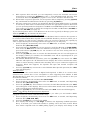
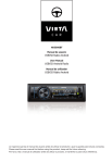
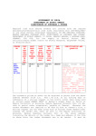
(9) FUNC Keys
These three keys select many of the most important operating features of the
transceiver. When pressing the [F] key, the current function of that key appears above
each of the [A], [B], [C] keys (along the bottom of the LCD); rotating the SEL knob
scrolls the display through eleven rows of functions available for use via the [A], [B], [C]
keys.
The available features are shown in chart below.
1
2
3
4
5
6
[A] Key
A/B
Press the [A] key to switch between
VFO-A and VFO-B on the display.
MW
Press and hold the [A] key for 1/2
second to transfer the contents of the
VFO into a Memory register.
STO
Press the [A] key to store the contents
of the VFO into a QMB register.
RPT
Press the [A] key to select the direction
of the uplink frequency shift (“–,” “+,” or
simplex) during FM repeater operation.
Press and hold the [A] key for 1/2
second to recall Menu #42 (for setting
the shift frequency).
SCN
Press the [A] key to initiate scanning
(in the direction of higher frequency).
SSM
[B] Key
A=B
Press and hold the [B] key for 1/2
second to copy the contents of
VFO-A into the VFO-B register, so
that the two VFOs’ contains will
be identical.
MC
Press the [B] key to designates
the current Memory channel to be
“skipped” during scanning.
RCL
Press the [B] key to recall the
QMB Memory.
REV
Press the [B] key to reverse the
transmit and receive frequency
while working through a repeater.
[C] Key
SPL
Press the [C] key to activates Split
frequency operation between VFO-A and
VFO-B.
TAG
Press the [C] key to select the display type
(Frequency or Alpha-numeric Tag) during
Memory operation.
PMS
Press the [C] key to activates the
Programmable Memory Scan.
TON
Press the [C] key to activate the CTCSS or
DCS operation.
Press and hold the [C] key for 1/2 second to
recall Menu #48 (for selecting the CTCSS
tone frequency).
PRI
Press the [B] key to activate the
priority scan.
SCH
1
DW
Press the [C] key to activates the Dual
Watch system.
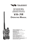
ART
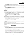
FT-817
OPERATING MANUAL
Press the [A] key to activate the
Spectrum Scope feature.
7
Press and hold the [A] key for 1/2
second to recall Menu #43 (for selecting
the sweep mode).
IPO
Press the [A] key to bypass the receiver
preamplifier, thereby causing Intercept
Point Optimization for improved
characteristics.
The IPO feature does not function on
144/430 MHz.
8
NB
Press the [A] key to activate the
receiver’s IF noise Blanker.
9
PWR
Press the [A] key to select the
transmitter power output level (LOW 1,
LOW 2, LOW 3, or HIGH).
10
VOX
Press the [A] key to enable the VOX
(voice-operated transmitter switching
system) in the SSB, AM, and FM
modes.
11
Press and hold the [A] key for 1/2
second to recall Menu #51 (for setting
the VOX Gain level).
CHG
Press the [A] key to initiate the battery
charging.
Press the [B] key to activate
Smart SearchTM operation.
ATT
Press the [B] key to engage the
receiver front-end attenuator,
which will reduce all signals and
noise by approximately 10 dB.
The ATT feature does not function
on 144/430 MHz.
AGC
Press the [B] key to select the
recovery time (FAST, SLOW, or
AUTO) for the receiver’s AGC
system.
MTR
Press the [B] key to select the
display function of the meter in
the transmit mode (Power, ALC,
SWR, or MOD indication).
BK
Press the [B] key to activate CW
Break-in operation.
Press the [C] key to initiate the AutoRange Transponder mode.
Press and hold the [C] key for 1/2 second to
recall Menu #09 (for selecting the ARTS
beep option).
NAR
Press the [C] key to activate the “Narrow”
filter mode in the CW (optional YF-122C
required) and SSB (optional YF-122S
required) mode.
On FM mode, it also select the lowdeviation mode required for HF FM
operation on 29 MHz.
Press and hold the [C] key for 1/2 second to
recall Menu #38 (for Enable/disable the
optional filter).
–
–
KYR
Press the [C] key to activate the built-in
Electronic Keyer.
Press and hold the [B] key for 1/2
second to recall Menu #17 (for
setting the CW Delay time).
Press and hold the [C] key for 1/2 second to
recall Menu #21 (for setting the Keyer
speed).
VTL
Press the [B] key to display the
current battery voltage.
DSP
Press the [C] key to switches display
between Large Character and Small
Character mode.
Press and hold the [A] key for 1/2
second to recall Menu #11 (for selecting
the Charging period).
*The Operating Function number in this column does not appear on the LCD.
(10) BAND(DWN)/BAND(UP) Key
Pressing one of these keys momentarily will cause the frequency to be moved up or
down by one Frequency Band. The selections are available are:
… 1.8 MHz ! 3.5 MHz ! 7.0 MHz ! 10 MHz ! 14 MHz ! 15 MHz ! 18 MHz ! 24
MHz ! 28 MHz ! 50 MHz ! 88 MHz ! 108 MHz ! 144 MHz ! 430 MHz ! 1.8
MHz …
(11) MODE(!)/MODE(") Key
Pressing one of these keys momentarily will cause the operating mode. The selections
are available are:
… USB ! LSB ! CW ! CWR ! AM ! DIG ! PKT ! USB …
(12) HOME Key
Pressing this key momentarily to recalls a favorite “Home” frequency memory.
(13) SEL Knob
2
FT-817
OPERATING MANUAL
This detented rotary switch is used for many tuning, Memory selection, and Function
selection for the [A], [B], [C] keys of the transceiver.
(14) CLAR Key
Press this key momentarily to activate the Receiver Classifier feature. When this
feature is activated, the SEL knob is used to set a tuning offset of up to ±9.99 kHz.
Press and hold this key for 1/2 second to activate the IF Shift feature, which allows you
to use the SEL knob to adjust the center frequency of the IF filter’s passband response.
(15) ANT Jack
Connect the supplied 50/144/430 MHz rubber flex antenna (or another antenna
presenting a 50Ω impedance).
In its default setting, this jack does not function on HF band. If you want to enable this
jack on HF band, recall and changes the Menu #07 settings.
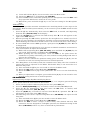
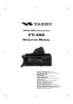
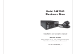
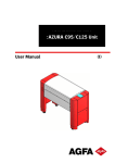
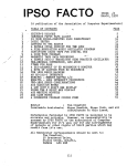
Side Panel Switch & Connectors
(1) MIC Jack
Connect the supplied MH-31 Hand Microphone.
(2) SP/PH Jack
This 3.5-mm, 2-pin jack provides variable audio output for an external speaker (4Ω ~
16Ω impedance) or Earphone. This audio level varies according to the setting of the
front panel’s AF knob.
Important Note: When insert the Earphone plug into this jack, the slide SP-PH switch
located on the right side of this jack MUST BE slide to the “PH” position to prevent the
injure your ear.
(3) SP-PH Switch
If you use the Earphone with this transceiver, move this switch to the “PH” position
before inserting the Earphone plug into the SP/PH Jack, to prevent the injure your ear.
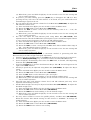
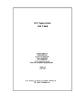
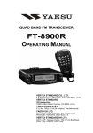
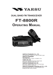
Rear Panel Connectors
(1) INPUT:13.8V Jack
This is the DC power supply connection for the transceiver when operate the
transceiver external power supply. Use the supplied DC cable to connect this jack to the
car battery or base station DC power supply, which must be capable of supplying at
least 2A @8 ~ 16 VDC. This jack is also use the battery charging for the optional FNB-72
battery pack.
(2) GND Terminal
For best performance and safety, this Ground lug should be connected to a good earth
ground using a short, heavy, braided cable.
(3) KEY Jack
This 3.5-mm, 3-pin jack is used for connection to a CW keyer paddle or a straight key.
(4) DATA Jack
This 6-pin, mini-DIN jack accepts AFSK or FSK input from a Terminal Node Controller
(TNC) or Terminal Unit (TU); it also provides fixed-level Receiver Audio Output, PushTo-Talk (PTT), and ground lines.
(5) ACC Jack
This 8-pin, mini-DIN jack is used for interfacing to a personal computer for control of
this transceiver using the CAT System. It is also used for Transceiver-to Transceiver
Cloning.
(6) ANT Jack
Connect your HF and/or 50 MHz antenna’s 50 Ω coaxial cable to this M-type (“SO-239”)
connector.
In its default setting, this jack does not function on 50/144/430 MHz bands. If you want
to enable this jack on 50/144/430 MHz bands, recall and changes the Menu #07 settings.
3
FT-817
OPERATING MANUAL
Operation
Turning the Transceiver On and Off
1. To turn the transceiver on, press and hold the PWR switch for one second.
2. To turn the transceiver off, again press and hold the PWR switch for one second.
Supply Voltage Display
When you turn on the transceiver, the dc supply voltage is indicated on the upper right
corner of the LCD for two seconds. After this interval, the display will resume its normal
indication of the operating mode (VFOa, VFOb, or Memory Channel Number). To view the
supply voltage at any time during operation:
1. Press the [F] key momentarily, then rotate the SEL knob to select Operating Function
Row [CHG, VLT, DSP] on the display.
2. Press the [B](VLT) key momentarily to display the supply voltage on the upper right
corner of the LCD.
3. To cancel the supply voltage display, again press the [B](VLT) key.
Operating Band Selection
This transceiver covers an incredibly wide frequency range, over which a number of
different operating modes are used. Therefore, this transceiver’s frequency coverage has
been divided into different operating band, each of with has its own ore-set channel steps
and operating modes. You can change the channel steps and operating mode later, of course,
per the next section.
To change the operating bands, press either the BAND(DWN) or BAND(UP) Key to move to
the next higher or lower operating band, respectively.
… 1.8 MHz ! 3.5 MHz ! 7.0 MHz ! 10 MHz ! 14 MHz ! 15 MHz ! 18 MHz ! 24
MHz ! 28 MHz ! 50 MHz ! 88 MHz ! 108 MHz ! 144 MHz ! 430 MHz ! 1.8
MHz …
Mode Selection
Press either MODE(!) or MODE(") key to move among the eight settings for the operating
modes, respectively.
… USB ! LSB ! CW ! CWR ! AM ! DIG ! PKT ! USB …
Adjusting the Audio Volume Level
Rotate the AF knob to set a comfortable listening level.
Note 1: When operating in the “DIG” or “PKT” modes, you may set the AF knob to any
comfortable setting, or even all the way off, because the output from the DATA jack is a
fixed-level audio signal.
Note 2: Start with the AF knob set fully counter-clockwise, especially when using FM (the
background noise on FM can be surprisingly loud)!
Setting the Operating Frequency
1. In the “SSB/CW/DIG” modes, rotate the DIAL knob to set the frequency. Clockwise
rotation of the DIAL increase the operating frequency.
2. In the “AM/FM/PKT” modes, rotate the SEL knob to set the frequency. Clockwise
rotation of the SEL increase the operating frequency.
3. You may also use the SEL knob to adjust the operating frequency in the “SSB/CW/DIG”
modes.
4. Rotate the SEL knob after pressing the SEL knob, change the operating frequency in 1
MHz step, allowing quick excursions around the band.
Note: Both the synthesizer’s steps and the tuning rate (the number of steps per rotation of
the DIAL) can be adjusted.
Stacked VFO System
1. Press the [F] key momentarily, then rotate the SEL knob, as needed, until Operating
Function Row [A/B, A=B, SPL] on the display.
2. Now press the [A](A/B) key to toggle between the “A
A” and “B
B” VFO. There are two such
VFOs provided on each Amateur band, so you may set VFO-A to the CW sub-band, and
4
FT-817
OPERATING MANUAL
VFO-B to the SSB sub-band, if you like. The operating mode will be preserved, along
with the frequency information, on each VFO.
Receiver Accessory
Clarifier (Receiver Incremental Tuning)
The Clarifier (RIT) allows you to set an offset of up to ±9.99 kHz of the receive frequency
relative to your transmit frequency. To achieve wider offset, you may use the “split”
operating mode, described later.
1. Press the [CLAR] switch momentarily to activate the Clarifier function.
2. Turn the SEL knob, which allows the receiver frequency to be varied over a range of
9.99 kHz.
3. When offsets the receiving frequency higher than transmit frequency, appear the “"”
icon at the right of the frequency display. Similarly, when offsets the receiving
frequency lower than transmit frequency, appear the “#” icon at the right of the
frequency display.
4. When the receiving frequency equal transmit frequency (Clarifier offset is zero) while
the Clarifier is activated, appear the “–” icon at the right of the frequency display.
5. To turn the Clarifier off, again press the [CLAR] switch momentarily.
6. To reset the Clarifier offset to zero, turn the Clarifier off, then turn the DIAL by any
amount. The Clarifier will reset to zero after the first “step” of the DIAL.
IF SHIFT
The receiver’s IF SHIFT feature is an effective interference-reduction tool, which allows you
to shift the passband response higher or lower without changing the pitch of the incoming
signal.
1. Press the [CLAR] switch for one second to activate the IF SHIFT feature. A “$”, “#,” or
“$” icon will appears at the right of the frequency display to inform the IF SHIFT’s
current position.
2. Rotate the SEL knob, as needed, to reduce or eliminate interference.
3. To turn the IF SHIFT feature off, again press the [CLAR] switch for one second. The
last setting of the IF SHIFT control will be retained until you change it again.
AGC (Automatic Gain Control)
The receiver recovery time constant may be modified to match your operating needs.
1. Press the [F] key momentarily, then rotate the SEL knob, as needed, until Operating
Function Row [NB, AGC] on the display.
2. Press the [B](AGC) key to toggle the AGC recovery time constant among the following
selection:
AGCauto % AGCfast --. AGCslow % AGCauto …
where “AGCauto” represents “AGCfast” on CW and DIG(AFSK), and “AGCslow” on the
voice modes.
Noise Blanker
The IF Noise Blanker may be useful in reducing or eliminating some types of impulse noise.
1. Press the [F] key momentarily, then rotate the SEL knob, as needed, until Operating
Function Row [NB, AGC] on the display.
2. Press the [A](NB) key to activate the Noise Blanker. The “!” icon will appears at the
right of the “NB” indicate.
3. Press the A](NB) key again to turn the Noise Blanker off.
IPO (Intercept Point Optimization)
The IPO feature bypasses the receiver RF preamplifier, thereby eliminating the preamp’s
gain. This feature is not available on the 144 MHz and 430 MHz.
1. Press the [F] key momentarily, then rotate the SEL knob, as needed, until Operating
Function Row [IPO, ATT, NAR] on the display.
2. Press the [A](IPO) key to bypass the receiver input preamplifier. The “!” icon will
appears at the right of the “IPO” indicate.
5
FT-817
OPERATING MANUAL
3. Press the [A](IPO) key once more to re-activate the preamp.
ATT (Front End Attenuator)
The Attenuator all signal (and noise) by 10 dB, and it may be used to make reception more
pleasant under extremely noisy conditions. This feature is not available on the 144 MHz and
430 MHz.
1. Press the [F] key momentarily, then rotate the SEL knob, as needed, until Operating
Function Row [IPO, ATT, NAR] on the display.
2. Press the [B](ATT) key to activate the Attenuator. The “!” icon will appears at the right
of the “ATT” indicate.
3. Press the [B](ATT) key once more to switch the Attenuator out of the receiver front end
circuit.
AM/FM DIAL
In the AM and FM modes, the DIAL knob is locked out (via Menu setting) so as to allow
“channelized” tuning on these modes. To adjust the operating frequency rotate the SEL
knob.
If you wish to enable the DIAL for tuning in the AM and FM modes, change the setting of
Menu #04.
1. Press and hold the [F] key for one second to enter the Menu mode.
2. Rotate the SEL knob to recall Menu #04 (AM&FM DL).
3. Rotate the DIAL knob to set this feature (“AM&FM DL”) to “ENABLE.”
4. Press and hold the [F] key for one second to save the new setting and exit to normal
operation.
Automatic Power-Off Feature
The APO feature helps conserve battery life by automatically turning the transceiver off
after a user-defined period of time within which there has been no dial or key activity. The
available selections for the time before power-off are 1 ~ 6 hours, as well as APO Off. The
default condition for the APO is OFF, and here is the procedure for activating it:
1. Press and hold the [F] key for one second to enter the Menu mode.
2. Rotate the SEL knob to recall Menu #08 (APO TIME).
3. Rotate the DIAL knob to select the desired time period after which the radio will
automatically shut down.
4. Press and hold the [F] key for one second to save the new setting and exit to normal
operation.
Once you have programmed a time interval, the APO countdown timer will start whenever
some front panel action (tuning, transmission, etc.) ends.
When activate the APO, appear the “TIMER” icon at the center bottom on the LCD. If there
is no action by you within the time interval programmed, the microprocessor will shut down
the radio automatically. Just press and hold the PWR switch for one second to turn it back
on, as usual.
Transmitter Operation
SSB Transmission
Basic Setup/Operation
1. Press the MODE(!)/MODE(") key so to select the SSB (LSB/USB) mode. If you are
operating on the 10 MHz or lower bands, to select the LSB mode. If you are operating on
the 14 MHz or higher bands, to select the USB mode.
2. Press the [F] key momentarily, then rotate the SEL knob, as needed, until Operating
Function Row [PWR, MTR] on the display, then press the [B](MTR) key to select the
“ALC” meter function (appear “alc” at the right side of the “MTR” icon.).
3. Press the microphone’s PTT switch, and speak into the microphone in a normal voice
while watching the meter. The ideal audio input level to the transmitter from the
microphone will cause ??? “segment” of indication on the ALC meter. Release the PTT
switch to return to receive mode.
4. If the ALC meter is too high, or too low, you may need to reset the Microphone Gain:
6
FT-817
OPERATING MANUAL
(1) Press and hold the [F] key for one second to enter the Menu mode.
(2) Rotate the SEL knob to recall Menu #46 (SSB MIC).
(3) Close the PTT switch, and while speaking into the microphone rotate the DIAL until
the proper ALC indication is achieved on voice peaks.
(4) When done, press and hold the [F] key to save the new setting for the Microphone
Gain.
VOX Operation
The VOX system provides automatic transmit/receive switching based on voice input to the
microphone. With the VOX system enabled, you do not need to press the PTT switch in order
to transmit.
1. Press the [F] key momentarily, then rotate the SEL knob, as needed, until Operating
Function Row [VOX, BK, KYR] on the display.
2. Press the [A](VOX) key to activate the VOX circuitly. The “!” icon will appears at the
right of the “VOX” indicate.
3. Without pressing the PTT switch, speak into the microphone in a normal voice level.
When you start speaking, the transmitter should be activated automatically. When you
finish skeaking, the transceiver should return to the receive mode (after a short delay).
4. To cancel VOX and return to PTT operation., again press the [A](VOX) key. The “!” icon
is disappeared.
5. The VOX Gain may be adjusted, so as to prevent accidental transmitter activation in a
noisy environment. To adjust the VOX Gain:
(1) While still in Operating Row [VOX, BK, KYR], press and hold the [A](VOX) key for
one second. This instantly recall Menu #51 (VOX GAIN).
(2) While speaking into the microphone, rotate the DIAL to the point where the
transmitter is quickly activated by your voice, without causing background noise to
activate the transmitter.
(3) When you have selected the optimum setting, press and hold the [F] key for one
second to save the new settings and return to normal operation.
6. The “Hang-Time” of the VOX system (the transmit-receive delay after the cessation of
speech) may also be adjusted via the Menu. The default delay is 1/2 second. To set a
different delay time:
(1) Press and hold the [F] key for one second to activate the Menu mode.
(2) Rotate the SEL knob to select Menu #50 (VOX DELAY).
(3) Rotate the DIAL while saying a brief syllable like “Ah” so as to set the desired delay
time.
(4) When you adjustment is complete, press and hold the [F] key for one second to save
the new setting and return to normal operation.
CW Transmission
Operation using Straight Key/External Keying Device
When using a straight key, an external electronic keyer, or a computer-generated keying
device, please follow the instructions in this section.
1. Insert your key’s (three-conductor) plug into the rear-panel KEY jack.
2. Press the MODE(!)/MODE(") key, as needed, to select the CW (CW/CWR) mode.
3. Press the [F] key momentarily, then then rotate the SEL knob, as needed, until
Operating Function Row [VOX, BK, KYR].
4. Press the [B](BK) key, as needed, to activate “Semi Break-In” operation. The “!” icon
will appears at the right of the “BK” indicate.
5. The CW hang time can be adjusted using Menu #17 (CW DELAY). To adjust the CW
hang time:
(1) Press and hold in the [F] key for one second to enter the Menu mode.
(2) Rotate the SEL knob to select Menu #17 (CW DELAY).
(3) Rotate the DIAL to select a longer or shorter delay time (default: 250 ms). This
transceiver was not designed for “full QSK” operation, the minimum setting of this
Menu (CW DELAY) will be very close to full break-in performance.
7
FT-817
OPERATING MANUAL
(4) When done, press and hold the [F] key for one second to save the new setting and
exit to normal operation.
6. To practice your CW sending, press the [B](BK) key to disappear the “!” icon. Now,
pressing the key will cause the CW sidetone to be heard, but your radio will not be
transmitting a signal on the air.
7. You can adjust the CW sidetone volume level via Menu #44 (SIDETONE). To adjust the
CW sidetone volume level:
(1) Press and hold in the [F] key for one second to enter the Menu mode.
(2) Rotate the SEL knob to select Menu #44 (SIDETONE).
(3) Rotate the DIAL to select a new level; on the arbitrary scale of “0” ~ “100,” the
default value is “50.”
(4) When done, press and hold the [F] key for one second to save the new setting and
exit to normal operation.
8. You also can adjust the CW sidetone pitch using Menu #20 (CW PITCH). This
adjustment also controls the BFO offset (actual pitch of your transmitted signal relative
to your current receive frequency). To adjust the CW sidetone pitch:
(1) Press and hold in the [F] key for one second to enter the Menu mode.
(2) Rotate the SEL knob to select Menu #20 (CW PITCH).
(3) Rotate the DIAL to select a new pitch tone/BFO offset. The available offset range is
300 ~ 1000 Hz (default value is “700 Hz”).
(4) When done, press and hold the [F] key for one second to save the new setting and
exit to normal operation.
Operation using Built-in Electronic Keyer
The built-in Electronic Keyer provides a convenient method of generating CW. The
Electronic Keyer includes weight and speed adjustment.
1. Connect your keyer paddle’s cable to the KEY jack on the rear panel of the transceiver.
2. Press the MODE(!)/MODE(") key, as needed, to select the CW (CW/CWR) mode.
3. Press the [F] key momentarily, then rotate the SEL knob, as needed, until Operating
Function Row [VOX, BK, KYR].
4. Press the [C](KYR) key to activate the Electronic Keyer. The “!” icon will appears at the
right of the “KTR” indicate.
5. The Keyer speed may be adjusted using Menu #21 (CW SPEED). To adjust the Keyer
speed:
(1) Press and hold in the [F] key for one second to enter the Menu mode.
(2) Rotate the SEL knob to select Menu #21 (CW SPEED).
(3) Press the SEL knob to select between “cpm” and “wpm.”
(4) Rotate the DIAL knob, while sending, to set the desired sending speed.
(5) When done, press and hold the [F] key for one second to save the new setting and
exit to normal operation.
6. The CW hang time, CW sidetone volume level, and CW sidetone pitch may all be
adjusted as described previously.
7. The Dot:Dash weight ratio may be adjusted via Menu #22 (CW WEIGHT). To adjust the
Dot:Dash weight ratio:
(1) Press and hold in the [F] key for one second to enter the Menu mode.
(2) Rotate the SEL knob to select Menu #22 (CW WEIGHT).
(3) Rotate the DIAL knob, while sending, to set the desired weight.
(4) When done, press and hold the [F] key for one second to save the new setting and
exit to normal operation.
8. You may select normal or reverse the paddle polarity via Menu #19 (CW PADDLE).
When this feature The default setting for this feature is “NOMAL.” To change the
paddle polarity:
(1) Press and hold in the [F] key for one second to enter the Menu mode.
(2) Rotate the SEL knob to select Menu #19 (CW PADDLE).
(3) Rotate the DIAL knob to select a new setting.
8
FT-817
OPERATING MANUAL
(4) When done, press and hold the [F] key for one second to save the new setting and
exit to normal operation.
9. You also can adjust the CW sidetone volume and pitch via Menu Item described
previously.
FM Transmission
Basic Setup/Operation
1. Press the MODE(!)/MODE(") key so to select the FM mode.
2. Press the microphone’s PTT switch, and speak into the microphone in a normal voice.
3. Release the PTT switch to return to receive mode.
4. If you get reports that your voice is too high or too low, you may need to adjust the FMmode microphone gain. The procedure is similar to that used on SSB:
(1) Press the [F] key momentarily, then rotate the SEL knob, as needed, until
Operating Function Row [PWR, MTR] on the display, then press the [B](MTR) key to
select the “Deviation” meter function (appear “mod” at the right side of the “MTR”
icon.).
(2) Press and hold the [F] key for one second to enter the Menu mode.
(3) Rotate the SEL knob to recall Menu #29 (FM MIC).
(4) Close the PTT switch, and while speaking into the microphone rotate the DIAL until
the proper MOD indication is achieved on voice peaks.
(5) When done, press and hold the [F] key to save the new setting for the FM-mode
microphone gain.
5. The VOX feature is operational during FM transmission. From Operating Function
Row [VOX, BK, KYR], press the [A](VOX) key to activate/deactivate VOX.
Repeater Operation
1. Press the [F] key momentarily, then rotate the SEL knob, as needed, until Operating
Function Row [RPT, REV, TON].
2. Press the [A](RPT) key to activate repeater operation. One press of the [A](RPT) key will
have set the transceiver for “Minus Shift” operation. In this situation, you will observe
the “–” indicator on the display. The transmitter frequency will be shifted down by a
default value so as to access the repeater input frequency. If your repeater uses a
positive shift (instead of negative), press the [A](RPT) key again; the “+” indicator will
replace the “–” indicator on the display.
3. If the default repeater shifts is not appropriate for your area, it may be set
independently for each band*. To change the repeater shifts:
(1) Press and hold the [A](RPT) key for one second. This instantly recalls Menu #42
(RPT SHFT).
(2) Rotate the DIAL knob to select the desired shift frequency.
(3) When done, press and hold the [A](RPT) key for one second so save the new setting
and exit to normal operation.
4. Press the [C](TON) key to activate the CTCSS tone encoder to repeater access tone. One
press of the [C](TON) key will activate the CTCSS tone encoder. In this situation, you
will observe the “T” indicator on the display.
5. If the default repeater access tone are not appropriate for your area, it also may be set
independently for each band. To change the repeater access tone:
(1) Press and hold the [C](TON) key for one second. This instantly recalls Menu #48
(TONE FREQ).
(2) Rotate the DIAL knob to select the desired CTCSS frequency.
(3) When done, press and hold the [C](TON) key for one second so save the new setting
and exit to normal operation.
6. Set the transceiver’s receiver to the repeater output (downlink) frequency.
7. Close the PTT switch and speak into the microphone. You will observe that the
transmitted frequency has shifted according to the setting of the [A](RPT) key with a
low level CTCSS tone.
8. Release the PTT switch to return to the Receive mode.
9
FT-817
OPERATING MANUAL
9.
With repeater shift activated, you can temporarily reverse the transmit and receive
frequencies by pressing the [B](REV) key. The “–” icon will blinks while “Reverse” shift
is activated. Press the [B](REV) key again to revert to the “Normal” shift direction.
10. When finish a repeater operation, set the repeater shift to simplex by pressing [A](RPT)
key, and disable the CTCSS tone encoder by pressing [C](TON) key.
11. On many transceiver versions, the Automatic Repeater Shift (ARS) feature is enabled
at the factory. This feature automatically activates the appropriate repeater shift when
you are operating inside the designated 144 MHz or 430 MHz FM repeater sub-bands in
your country. If you wish to change the settings for the ARS, use Menu #01 (144 ARS) or
Menu #02 (430 ARS) (see page ??).
If your local repeaters need a 1750-Hz burst tone for access (typically in Europe), press and
hold the [HOME] key to transmit the burst tone.
CTCSS Encoder and Tone Squelch Operation
Many repeaters require a CTCSS Encode or 1750 Hz Burst Tone in order for the repeater to
be activated. The CTCSS Tone Squelch feature (CTCSS “Decoder”), moreover, allows you to
monitor silently for calls on busy channels, with your receiver’s Squelch only opening up
when a signal bearing the matching CTCSS tone appears on your frequency.
1. Press the [F] key momentarily, then rotate the SEL knob, as needed, until Operating
Function Row [RPT, REV, TON].
2. Press and hold the [C](TON) key for one second to recall the Menu # 48 (TONE FREQ),
then rotate the DIAL knob to select the CTCSS tone frequency, as needed. When done,
press and hold the [C](TON) key for one second so save the new setting and exit to
normal operation.
3. Press the [C](TON) key once to activate the Tone Encoder (the “T” icon will appear on
the display). When you transmit, the Subaudible tone will be superimposed on your
signal, allowing repeater access.
4. For CTCSS Encode/Decode operation, press the [C](TON) key once more; the “TSQ”
indicator will replace the “T” indication on the display. The receiver will become silent,
unless a station bearing a CTCSS tone matching that of your transceiver appears on
frequency. When this happens, the Squelch will open and normal reception will
commence.
5. Press the [C](TON) key once mode to cancel CTCSS Tone Squelch operation (the “TSQ”
icons will disappear).
DCS Operation
Another form of tone access control is Digital Code Squelch, or DCS. It is a newer, more
advanced tone system that is less susceptible to false triggering than CTCSS. A DCS
Encoder/Decoder is built into your transceiver, and operation is very similar to that just
described for CTCSS.
1. Set the desired DCS code via Menu #23 (DCS CODE).
2. Press the [F] key momentarily, then rotate the SEL knob, as needed, until Operating
Function Row [RPT, REV, TON].
3. Press the [C](TON) key three thimes to activate the DCS Encoder/Decoder (the “DCS”
icon will appear on the display). The receiver will remain muted until a matching DCS
code is received on an incoming signal.
4. Press the [C](TON) key once to cancel the DCS (the “DCS” icon icons will disappear).
ARTSTM (Auto Range Transpond System) Operation
The ARTSTM system uses DCS signaling to inform you when you and another ARTSequipped station are within communications range.
1. Press the [F] key momentarily, then rotate the SEL knob, as needed, until Operating
Function Row [SSM, SCH, ART].
2. Press the [C](ART) key to activate the ARTS.
3. Your display will change to “out range” to indicate the beginning of ARTS operation.
Every 15 seconds, your radio will transmit a “polling” call to the other station. When
that station responds with its ARTS polling signal, your display will change to “in
10
FT-817
OPERATING MANUAL
range” to confirm his response.
To cancel ARTS operation, press the [C](ART) key again (the “out range” or “in range”
will disappear from the LCD).
The ARTS feature offers a choice of beep options to alert you to the current status of ARTS
operation. Check out MENU #09 (ARTS BEEP) on page 85.
CW Identifier Setup
The ARTS feature includes a CW identifier. The radio can be instructed to send “DE (your
callsign) K” in Morse code every ten minutes during ARTS operation.
To program the CW IDer, use Menu #31 (ID), as described on page ??. And to activate the CW
IDer, use Menu #18 (CW ID).
Split Frequency Operation
This transceiver provides convenient split-frequency operation, using the VFO-A and VFOB, for DX working and other operating situations requiring unique split frequency pairs.
The example below will describe a split-frequency DX situation on the 20-meter band, with a
DX station transmitting on 14.025 MHz, listening 10 kHz higher in the band.
1. With the VFO-A set to 14.035.00 MHz CW (DX station’s listening frequency).
2. Press the [F] key momentarily, then rotate the SEL knob, as needed, until Operating
Function Row [A/B, A=B, SPL].
3. Pess the [A](A/B) key momentarily to VFO-B.
4. Tune the VFO-B frequency to 14.025.00 MHz (DX station’s transmitting frequency).
5. Press the [C](SPL) key momentarily. The transceiver will now transmit using the VFOA frequency, and will receive using the VFO-B frequency. The “S” icon will appear on
the display.
6. To listen to the pile-up calling the DX station (so as to align your frequency more closely
to that of the station being worked by the DX), the VFO-B will be tuning in the vicinity
of 14.035 MHz, and you can zero in on the DX station’s listening frequency by tuning in
on the station in QSO with the DX.
7. Press the [C](SPL) key once more to cancel split operation, and the “S” icon will
disappear from the display.
Time-Out Timer
Most often used on FM, the transmitter’s Time-Out Timer (TOT) feature disables the
transmitter after a user-defined period of transmission. This feature may be useful in
preventing a “stuck microphone” (accidental closure of the PTT switch) from causing
interference to other users.
To activate the Time-Out Timer:
1. Press and hold the [F] key for one second to enter the Menu mode.
2. Rotate the SEL knob to recall Menu #49 (TOT TIME).
3. The default setting for this feature is “off.” Rotate the DIAL knob to set a new setting
from 1 minute to 20 minutes.
4. When you have made your selection, press and hold the [F] key for one second to save
the new setting and exit to normal operation.
4.
Memory Operation
QMB Channel
QMB Channel Storage
1. Tune in the desired frequency and set the operating mode and bandwidth.
2. Press and hold the [V/M] key until a double “beep” is heard. The double beep provides
audible confirmation that the data is stored into memory.
QMB Channel Recall
1. Press the [F] key momentarily, then rotate the SEL knob, as needed, until Operating
Function Row [STO, RCL, RCL].
2. Press the [B](RCL) key momentarily to recall the QMB memory. The “QMB” will appear
at the upper right corner on the LCD.
3. Press the [B](RCL) key once more to return to the previous frequency (either a VFO
11
FT-817
OPERATING MANUAL
frequency or a Memory channel).
Note: If you move the DIAL knob or SEL knob while in the QMB mode, you can change
frequencies as if you were in a “VFO” mode. You also can change operating mode by pressing
MODE(!) or MODE(") key. When this is done, the “MTQMB” will appear in the display.
Press the [B](RCL) key once more to return to the originally-stored QMB frequency.
Memory Operation on “Regular”
egular” Memory Channels
Normal (“Simplex”) Memory Storage
1. Tune in the desired frequency, and set the operating mode and bandwidth.
2. Press the [F] key momentarily, then rotate the SEL knob, as needed, until Operating
Function Row [MW, MC, TAG].
3. Press the [A](MC) key momentarily to enter the “Memory Check” mode, which is used to
find an unused memory channel. The frequency stored (if any) on the current memory
channel will be shown in the display.
4. Rotate the SEL knob to select the channel on which you wish to store the current
frequency data.
5. Press and hold in the [A](MC) key for one second until you hear a double beep, which
confirms that the frequency information was successfully stored.
Split-Frequency Memory Storage
You can also store “Split” frequencies, such as when operating on a repeater system not
utilizing a “standard” offset. This procedure may also be used for DX work on 7 MHz SSB,
etc.
1. In the VFO mode, set the desired Receive frequency and mode.
2. Press the [F] key momentarily, then rotate the SEL knob, as needed, until Operating
Function Row [MW, MC, TAG].
3. Press the [A](MC) key momentarily to enter the “Memory Check” mode, which is used to
find an unused memory channel. The frequency stored (if any) on the current memory
channel will be shown in the display.
4. Rotate the SEL knob to select the channel on which you wish to store the current
frequency data.
5. Press and hold in the [A](MC) key for one second until you hear a double beep, which
confirms that the Receive frequency data is now stored.
6. Now, set the desired Transmit frequency and mode.
7. Press and hold the [A](MC) key for one second; do not rotate the SEL knob!
8. While “memory channel number” is blinking, press and hold the PTT switch, again
press and hold the [A](MC) key for one second. The double “beep” will confirm that
independent Transmit frequency data is now stored. You may release the PTT switch.
Note: In step 8 above, pressing the PTT switch does not activate the transmitter. It simply
sends a signal to the microprocessor that an independent Transmit frequency is being stored
on the same channel as a previously-stored Receive frequency.
Memory Channel Recall
1. If you currently are in the VFO tuning mode, press the [V/M] key once to enter the
“Memory” mode (“memory channel number” will appear on the display placed by
“VFOa” or “VFOb”).
2. To select another memory channel, turn the SEL knob.
3. When your memory channels are partitioned into Memory Groups via Memu Item #34,
to change Memory Groups; press the SEL knob momentarily (a Group Number (“a” ~
“j”) will blinks), then turn the SEL knob to step through the channels until you enter
another. You may now press the SEL knob once more to restrict memory channel access
to the newly- selected Group.
4. Once you are operating on a memory channel, you may tune off of the originallymemorized frequency (as though you were in the VFO mode). Just rotate the DIAL
knob; the “Memory Channel Number” will be replaced by one which indicates “MTUNE,”
indicating that you have now shifted into the “Memory Tuning” mode. When operating
the Memory Tuning mode, if you find another frequency you wish to store into another
12
FT-817
OPERATING MANUAL
memory channel, just press the [A](MC) key momentarily, select a new memory channel
via the SEL knob, then press and hold the [A](MC) key until you hear the double beep.
5. To exit the Memory Tuning mode, press the [V/M] key as follows:
& One touch of the [V/M] key returns you to the original memory frequency.
& A second touch of the [V/M] key will cause you to exit the Memory mode and return
to the VFO mode (the “memory channel number” will be replaced by “VFOa” or
“VFOb”.
Note: When operating on a “Split” frequency memory, the “+,–“ indication will appear on the
LCD.
Memory Operation on “HOME”
HOME” Channel Memory
Four Special one-touch “Home” channels are available, for special frequencies you use often.
Either “simplex” or “split” frequency/mode data may be stored in the “Home” channel
locations. Special “Home” channels are available for HF (any frequency between 1.8 and
29.7 MHz), 50 MHz, 144 MHz, and 430 MHz.
These memories may prove particularly useful for monitoring propagation beacons,
providing one-touch recall of the beacon frequency for quick checks of band condition.
HOME Channel Storage
1. Tune the desired frequency, and set the operating mode.
2. Press the [F] key momentarily, then rotate the SEL knob, as needed, until Operating
Function Row [MW, MC, TAG].
3. Press the [A](MW) key momentarily to enter the “Memory Check” mode.
4. Press and hold the [HOME] key for one second. This stores the frequency data into the
“Home” channel location.
5. If you wish to store a “Split” frequency pair into the “Home” channel, store the Receive
frequency in steps 1 ~ 4 above. Now set the desired Transmit frequency.
6. Once more, press the [A](MW) key momentarily.
7. Press and hold the microphone’s PTT switch; while holding the PTT switch, again press
and hold the [HOME] key for one second. This stores the transmit frequency data into
the “Home” channel location.
HOME Channel Recall
1. Press the [HOME] key momentarily to recall the Home Channel on the band group
where you currently are operating (HF, 50 MHz, 144 MHz, or 430 MHz). The “HOME”
will appear on the display.
2. Press the [HOME] key once more to return to the previously-used frequency (either a
VFO frequency or a memory channel).
Memory Mode Accessory
Labeling Memory
You may wish to append an alpha-numeric “Tag” (label) to a memory or memories, to aid in
recollection of the channel’s intended use (such as a club name, etc.). This is easily
accomplished using the Menu mode.
1. Recall the memory channel onto which you wish to appended a label.
2. Press and hold the [F] key for one second to enter the Menu mode.
3. Rotate the SEL knob to recall Menu #35 (MEM TAG).
4. Press the SEL knob to enable the programming of the label.
5. Rotate the DIAL knob to select the first character (number, letter, or symbol) in the
name you with to store, then rotate the SEL knob clockwise to move to the next
character.
6. Again rotate the DIAL knob to select the next number, letter, or symbol, then rotate the
SEL knob clockwise to move to the next character’s slot.
7. Repeat step 6 as many times as necessary to complete the name tag for the memory,
then press and hold the [F] key for one second to save the A/N (Alpha-Numeric) name
entry and exit to normal operation.
During “MR” (Memory Recall) operation, press the [F] key momentarily, then rotate the SEL
knob, as needed, until Operating Function Row [MW, MC, TAG]. Press the [C](TAG) key
13
FT-817
OPERATING MANUAL
momentarily to activate the alpha-numeric Tag. Repeatedly press this key will toggle
operation between “Frequency” display and “Tag” display.
Note: You can recall the Menu #35 (MEM TAG) instantly by press and hold the [C](TAG) key
for one second.
Spectrum Scope Operation
The Spectrum Scope allows viewing of operating activity on 5 channels above and 5 channels
below the current operating channel in the VFO mode.
The display indicates the relative signal strength on channels immediately adjacent to the
current operating frequency.
Two basic operating modes for Spectrum Scope are available:
CONT: In this mode, the transceiver sweeps the current band repeatedly until the
Spectrum Scope is turned off.
CHK: In this mode, the transceiver sweeps the current band one cycle every 10
seconds.
Setting the Spectrum Scope Mode
1. Press and hold the [F] key for one second to enter the Menu mode
2. Rotate the SEL knob to select Menu #43 (SCOPE).
3. Rotate the DIAL to select the desired sweep mode (see above).
4. When you have made your selection, press and hold the [F] key for one second to save
the new setting and exit to normal operation.
Activate the Spectrum Scope
1. Set the transceiver to the VFO mode in the desired band.
2. Press the [F] key momentarily, then rotate the SEL knob, as needed, until Operating
Function Row [SSM, SCH, ART].
3. Press the [A](SSM) key momentarily to start the Spectrum Scope.
4. When the Spectrum Scope is in operation, the relative signal strength of stations on
channels immediately adjacent to the current frequency will be indicated on the display.
5. To disable the Spectrum Scope, press the [A](SSM) key once more.
Note: The receiver’s audio output and S-meter are disabled when using the Spectrum Scope.
Smart Searc
Search Operation
The Smart SearchTM feature automatically stores frequencies where activity is encountered
on the current band. When Smart SearchTM is engaged, the transceiver quickly searches
above your current frequency, storing active frequencies as it goes (without stopping on
them even momentarily). These frequencies are stored in a special Smart SearchTM memory
bank, consisting of 50 memories. This feature available on the FM and AM modes. This
feature is especially helpful when traveling, as you can instantly store active FM repeater
frequencies without having to look up the frequencies in a reference book.
1. Set the SQL knob to the point where background noise is silenced. A typical setting, for
effective Smart SearchTM operation, will be at 12 o’clock or slightly clockwise from this
position.
2. Set the VFO frequency on which you wish to begin the search (the Smart SearchTM
feature is available on the VFO mode only).
3. Press the [F] key momentarily, then rotate the SEL knob, as needed, until Operating
Function Row [SSM, SCH, ART].
4. Now press the [B](SCH) key momentarily, the blinking “SRCH” appear on the LCD and
the transceiver will sweep upward on the current band, loading channels on which it
encounters a signal strong enough to open the squelch.
5. All channels where activity is present (up to 50 channels) will be loaded into the Smart
SearchTM memories. Whether or not all 50 memories are filled, the search will stop after
one sweep.
6. Now you can turn the SEL knob to select the Smart SearchTM memories.
7. To disable Smart SearchTM operation, press the [B](SCH) key momentarily.
14
FT-817
OPERATING MANUAL
Note: These memories are so-called “soft” memories; they will be lost if you initiate a new
Smart SearchTM sweep of the band.
Scanning Operation
This transceiver contains a wide variety of scanning capabilities. Whether you are in the
VFO mode or one of the memory modes, scanning operation is fundamentally identical in all
configurations, but with the following differences:
' In the VFO mode, scanning causes the transceiver to sweep up or down the band,
pausing or halting on any signal encountered;
' In the Memory mode, the scanner will scan the programmed memories, and can be
instructed to skip certain memories during scanning;
' In the Programmable Memory Scan (PMS) mode, the scanner will scan the band
within user-programmed frequency limits.
Scanning Operation
1. Set the SQL knob to the point where background noise is silenced. A typical setting, for
effective scanning operation, will be at 12 o’olock or slightly clockwise from this
position.
2. Set the transceiver into the operating configuration in which you wish to scan (VFO or
Memory: PMS describe later).
8. Press the [F] key momentarily, then rotate the SEL knob, as needed, until Operating
Function Row [SCN, PRI, DW].
3. Press the [A](SCN) key momentarily to start upward scan (toward higher frequencies or
higher memory channel numbers).
You may also press and hold in either the [UP] or [DWN] key on the microphone for ½
second to initiate upward or downward scanning, respectively, if Menu #37 (MIN
SCAN) set to “ON.”
4. Rotate the DIAL knob counterclockwise to toggle the scanning direction downward.
5. The scanner will now cause the transceiver to increment in the chosen direction until a
signal is detected. When a signal is encountered which opens the Squelch, the scanner
will pause until the signal disappears (at the end of the other station’s transmission), at
which point the scanner will resume. While the transceiver is in the “Pause” condition,
the decimal points in the frequency display area will blink. See “Scan-Resume Choices”
on page ?? for details of how to customize the resumption of scanning.
6. Press the PTT switch on the microphone to cancel scanning.
Scan Skip Programming (Memory Mode Only)
Among the memories you have programmed, there may be some stations which you do not
wish to scan. For example, weather broadcasts (which are transmitted continuously) will
cause the scanner to stop, and such channels may be skipped so as to avoid this
inconvenience.
To remove a channel from the scanning loop:
1. Press the [F] key momentarily, then rotate the SEL knob, as needed, until Operating
Function Row [MW, MC, TAG].
2. Recall the memory channel to be skipped.
3. Press the [B](MC) key momentarily. The “hyphen” in the memory channel number
changes to “dot”; this shows that this channel is now not included in the scanning loop.
4. Repeat steps 2 and 3 as many times as necessary to skip all the channels you do not
wish to scan.
5. Initiate memory scanning, you will observe that the channels you marked to be skipped
are not included in the scanning loop.
6. Press the PTT switch to stop the scan; you may now use the SEL knob to step through
the channels manually - one at a time - and you will observe that the “Skipped”
channels are, nonetheless, available for recall by manual means.
7. You may restore a previously-skipped channel to the scanning loop by selecting the
channel manually, then pressing the [B](MC) key momentarily so that the “dot” changes
15
FT-817
OPERATING MANUAL
to “hyphen.”
Programmable Memory Scan (PMS) Operation
To limit scanning (or tuning) within a particular frequency range, you can use the
Programmable Memory Scanning (PMS) feature, which utilizes special-purpose memory
pair (“M-PL” and “M-PU”). The PMS feature is especially useful in helping you to observe any
operating sub-band limits which apply to your Amateur license class.
PMS setup is simple to complete;
1. Store the upper and lower frequency limits of the range in a PMS memory pair (“M-PL”
and “M-PU”).
2. Press the [F] key momentarily, then rotate the SEL knob, as needed, until Operating
Function Row [STO, RCL, PMS].
3. Press the [C](PMS) momentarily, appear “PMS” at the upper left corner on the LCD and
activate PMS feature. Tuning and scanning are now within the limits of the selected
PMS memory pair, keeping operation inside this programmed range.
Example: Limit tuning & scanning to the 17-m band
1. Press the [V/M] key, as necessary, to recall the VFO mode. Tune to the low edge of the
17-m band (18.068 MHz) and select the desired mode (probably USB or CW).
2. Press the [F] key momentarily, then rotate the SEL knob, as needed, until Operating
Function Row [MW, MC, TAG].
3. Press the [A](MW) key momentarily, then turn the SEL knob to select memory channel
“MRPL.”
4. Press and hold the [A](MW) key for one second to write the VFO frequency (18.068
MHz) into “MRPL.”
5. Tune to the high edge of the 17-m band (18.168 MHz), leaving the mode unchanged.
6. Press the [A](MW) key momentarily, then turn the SELECT knob to select the memory
channel “MRPU.”
7. Press and hold the [A](MW) key for one second to write the VFO frequency (18.168
MHz) into “MRPU.”
8. Press the [F] key momentarily, then rotate the SEL knob one click clockwise to recall
Operating Function Row [STO, RCL, PMS].
9. Press the [C](PMS) key momentarily. Tuning and scanning are now limited to the
18.068 ~ 18.168-MHz range until you press the [V/M] key to return to memory or VFO
operation.
Scan-Resume Choices
Scanning operation requires that you have the transceiver’s audio squelched. The
transceiver then “assumes” that the opening of the squelch corresponds to the discovery of a
signal you may wish to listen to.
Once the scan has been halted, the transceiver pauses on the signal and stays locked on its
frequency for five seconds. Thereafter, scanning will resume whether or not the other
station’s transmission has ended. The scan resume interval (default: five second) can be
select from 3/5/10 seconds and off (continuously halted; To re-start the scanner press the
[A](SCN) key twice) via Menu #41 (RESUME) see page ??.
Dual Watch Operation
Dual Watch is similar, in some respects, to scanning. In Dual Watch, however, the
transceiver monitors (squelched) on the VFO-A frequency while periodically checking VFOB for activity (or vice-versa). A typical example might be for you to set VFO-A to 50.110 MHz,
watching for DX stations who might call CQ on that frequency, while periodically checking
28.885 MHz for stations reporting band openings on 6 meters.
To activate Dual Watch:
1. Set up transmit and receive operation on VFO-A, establishing your primary monitoring
frequency. Set up the frequency to be checked periodically on VFO-B.
2. Recall VFO-A, then rotate the SQL control until the background noise is just silenced.
3. Press the [F] key momentarily, then rotate the SEL knob, as needed, until Operating
Function Row [SCN, PRI, DW].
16
FT-817
OPERATING MANUAL
4.
5.
6.
7.
Press the [C](DW) key momentarily to activate Dual Watch operation (the “DW” icon
will appears at the bottom left corner on the LCD.
The transceiver will continue to monitor (squelched) on the current (VFO-A) frequency,
but every five seconds will switch briefly to VFO-B frequency, looking for activity.
If a station is detected on the VFO-B frequency, the transceiver will pause on the VFOB frequency (blink the decimal points).
Press the [C](DW) key again to cancel Dual Watch operation (“DW” icon will disappear).
Note that pressing the PTT switch on the microphone does not cancel Dual Watch
operation.
Menu Operation
The Menu System allows you to customize a wide variety of transceiver performance aspects
and operating characteristics.
Menu Selections
1. Press and hold the [F] key for one second. The Menu Item number and a brief title for
the Menu Item will appear in the display.
2. Rotate the SEL knob to select the Menu Item you wish to work on.
3. When you have chosen the desired Menu Item number, rotate the DIAL knob to change
the value or condition for the Menu Item.
Press the [HOME] key momentarily, reset its setting to the default
4. When you have made your selection, press and hold the [F] key for one second to save
the new setting and exit to the normal operation.
Menu Item 01 [144 ARS]
Function:
Function Activate/deactivate the Automatic Repeater Shift when operating on the 144 MHz band.
Available Values:
Values OFF/ON
Default:
Default ON (depends on transceiver version)
Menu Item 02 [430 ARS]
Function:
Function Activate/deactivate the Automatic Repeater Shift when operating on the 430 MHz band.
Available Values:
Values OFF/ON
Default:
Default ON (depends on transceiver version)
Menu Item 03 [9600 MIC]
Function:
Function Adjust the audio input level from the TNC during 9600 bps Packet operation.
Available Values:
Values 0 ~ 100
Default:
Default 50
Menu Item 04 [AM&FM DL]
Function:
Function Enabling/disabling the DIAL knob on the AM and FM mode.
Available Values:
Values ENABLE/DISABLE
Default:
Default DISABLE
Menu Item 05 [AM MIC]
Function:
Function Adjust the microphone gain level for the AM mode.
Available Values:
Values 0 ~ 100
Default:
Default 50
Menu Item 06 [AM STEP]
Function:
Function Select the tuning step for the SEL knob on the AM mode.
Available Values:
Values 2.5/5/9/10/12.5/25kHz
Default:
Default 5 kHz (depends on transceiver version)
Menu Item 07 [ANTENNA]
Function:
Function Select the antenna connector to be used on operating band.
Available Values:
Values FRONT/REAR
Default:
Default HF: REAR, 50/144/430 MHz: FRONT
Menu Item 08 [APO TIME]
Function:
Function Select the Auto Power Off time (time before power goes off).
Available Values:
Values OFF/1h ~ 6h
Default:
Default OFF
Menu Item 09 [ARTS BEEP]
Function:
Function Select the ARTS beep mode.
Available Values:
Values OFF/RANGE/ALL
17
FT-817
OPERATING MANUAL
Default:
Default RANGE
OFF: No alert beeps sound; you must look at the display to determine current ARTS status.
RANGE: A high tone beep will sound when the transceiver first detects that you are within range, and a low beep
will sound when the other station goes out of range.
ALL: A high tone beep will sound every time a polling transmission is received from the other station, and a low
beep will sound once when the other station goes out of range.
Menu Item 10 [BACKLIGHT]
Function:
Function Select the LCD lamp mode.
Available Values:
Values OFF/ON/AUTO
Default:
Default AUTO
OFF: Disable the LCD lamp.
ON: Illuminates the LCD lamp continuously.
AUTO: Illuminates the LCD lamp for five second when any key is pressed.
Menu Item 11 [BATT-CHG]
Function:
Function Select the battery charging time.
Available Values:
Values 6/8/10 h
Default:
Default 10 h
Menu Item 12 [BEEP FREQ]
Function:
Function Select the beep frequency
Available Values:
Values 440/880 Hz
Default:
Default 880 Hz
Menu Item 13 [BEEP VOL]
Function:
Function Select the beep volume
Available Values:
Values 0 ~ 100
Default:
Default 50
Menu Item 14 [CAT RATE]
Function:
Function Set the transceiver’s circuitry for the CAT baud rate to be used.
Available Values:
Values 4800/9600/38400 bps
Default:
Default 4800 bps
Menu Item 15 [COLOR]
Function:
Function Select the illumination color for the LCD backlight.
Available Values:
Values COLOR1(Blue)/COLOR2(Amber)
Default:
Default COLOR2(Amber)
Menu Item 16 [CONTRAST]
Function:
Function Setting of the display contrast level.
Available Values:
Values 1 ~ 12
Default:
Default 5
Menu Item 17 [CW DELAY]
Function:
Function Set the receiver recovery time during pseudo-VOX CW semi-break-in operation.
Available Values:
Values 10 ~ 500 msec
Default:
Default 250 msec
The recover time may be adjusted in steps of 10 msec. A longer delay may be preferable if you pause frequently
while sending.
Menu Item 18 [CW ID]
Function:
Function Enables/disables the CW identifier during ARTS operation.
Available Values:
Values OFF/ON
Default:
Default OFF
Menu Item 19 [CW PADDLE]
Function:
Function Select the keyer paddle operating mode.
Available Values:
Values NORMAL/REVERSE
Default:
Default NORMAL
NORMAL: Keyer paddle polarity is normal. The “dot” paddle produces dots and the “dash” paddle produces dashes.
REVERSE: Keyer paddle polarity is inverted. The “dot” paddle produces dashes and the “dash” paddle produces
dots.
Menu Item 20 [CW PITCH]
Function:
Function Setting of the pitch of the CW sidetone, BFO offset, and CW filter center frequencies.
Available Values:
Values 300 ~ 1000 Hz
Default:
Default 700 Hz
The CW pitch may be adjusted in steps of 50 Hz.
18
FT-817
OPERATING MANUAL
Menu Item 21 [CW SPEED]
Function:
Function Set the sending speed for the built-in Electronic keyer.
Available Values:
Values 4wpm ~ 60 wpm/20cpm ~ 300 cpm
Default:
Default 12wpm(60cpm)
This transceiver can be set the sending speed by two units (wpm: ward per minutes or cpm: character per minutes),
but does not independently.
To switch the units between “wpm” and “cpm,” just press the SEL knob
Menu Item 22 [CW WEIGHT]
Function:
Function Set the Dot:Dash ratio for the built-in electronic keyer.
Available Values:
Values 1:2.5 ~ 1:4.5
Default:
Default 1:3.0
Menu Item 23 [DCS CODE]
Function:
Function Setting the DCS code.
Available Values:
Values 104 Standard DCS codes
Default:
Default 023
Menu Item 24 [DIG DISP]
Function:
Function Define the displayed frequency offset during DIG (USER-L or USER-U) mode operation
Available Values:
Values –3000 ~ +3000 Hz
Default:
Default 0 Hz
Menu Item 25 [DIG MIC]
Function:
Function Adjust the audio input level from the equipment (such as TU or PSK-31 sound board) during DIG mode
operation
Available Values:
Values 0 ~ 100
Default:
Default 50
Menu Item 26 [DIG MODE]
Function:
Function Select the mode and sideband (if applicable) in the DIG mode.
Available Values:
Values RTTY/PSK31-L/PSK31-U/USER-L/USER-U
Default:
Default RTTY
RTTY: AFSK RTTY operation on the LSB mode
PSK31-L: PSK-31 operation on the LSB mode
PSK31-U: PSK-31 operation on the USB mode
USER-L: User-programmed costume operation based on LSB mode
USER-U: User-programmed costume operation based on USB mode
In the USER-L and USER-U modes, determine the display frequency offset and carrier frequency offset by menu
Item #24 (DIG DISP) and #27 (DIG SHIFT).
Menu Item 27 [DIG SHIFT]
Function:
Function Define the carrier frequency offset during DIG (USER-L or USER-U) mode operation
Available Values:
Values –3000 ~ +3000 Hz
Default:
Default 0 Hz
Menu Item 28 [EMERGENCY]: USA Version only
Function:
Function Enable Tx/Rx operation on the Alaska Emergency Channel, 5167.5 kHz.
Available Values:
Values OFF/ON
Default:
Default OFF
When this Menu Item is set to “ON,” the spot frequency of 5167.5 kHz will be enabled. To get to this frequency, use
the SEL knob to navigate; the Alaska Emergency Channel will be found between the Memory channel “M-PU” and
“M-001.”
Note: Use of this frequency is restricted to amateurs operating in (or within 92.6 km of) the U.S. State of Alaska,
and it is to be used for emergency communications only (involving the immediate protection of life or property).
Menu Item 29 [FM MIC]
Function:
Function Adjust the microphone gain level for the FM mode.
Available Values:
Values 0 ~ 100
Default:
Default 50
Menu Item 30 [FM STEP]
Function:
Function Select the tuning step for the SEL knob on the FM mode.
Available Values:
Values 5/6.25/10/12.5/15/20/25/50 kHz
Default:
Default 5 kHz (depends on operating band and transceiver version)
Menu Item 31 [ID]
Function:
Function Store the CE identifier callsign. Up to eight characters may be stored. The storage procedure is as
follows:
19
FT-817
OPERATING MANUAL
1.
Press the SEL knob momentarily to initiate callsign storing (appear the under bar on the first character
of the callsign).
2.
Rotate the DIAL knob to select the first letter/number of your callsign, then rotate the SEL knob one
click clockwise to save the first letter/number and move to the next entry position.
3.
Repeat the previous step as necessary to complete your callsign.
4.
Press the SEL knob to save your completed callsign and exit.
Default:
Default YAESU
Menu Item 32 [LOCK MODE]
Function:
Function Select the operation of the front panel’s [LOCK] key
Available Values:
Values DIAL/FREQ./PANEL
Default:
Default DIAL
DIAL: Lock DIAL knob only
FREQ.: Locks front panel keys and knobs which is regarding the frequency controls (such as
BAND(DWN)/BAND(UP) key, [A](A/B) key. Etc.).
PANEL: Locks all front keys and knobs (except [PWR] key and [LOCK] key)
Menu Item 33 [MAIN STEP]
Function:
Function Setting pd DIAL speed.
Available Values:
Values FINE/COARSE
Default:
Default FINE
You may choose between two speeds for the DIAL knob. Selecting “COARSE” cuts the tuning rate in half compared
to the default value.
Menu Item 34 [MEM GROUP]
Function:
Function Enable/disable the memory group feature
Available Values:
Values OFF/ON
Default:
Default OFF
When this Menu Item is set to “ON,” the 200 “standard” memory channels are partitioned into ten Memory Groups,
each holding up to 20 memory channels.
Menu Item 35 [MEM TAG]
Function:
Function Store Alpha-Numeric “Tags” for the memory channels.
Up to eight characters may be stored. The storage procedure is as follows:
1.
Recall the memory channel on which you wish to append a label.
2.
Recall this Menu Item (Menu #35 [MEM TAG]).
3.
Press the SEL knob momentarily to initiate callsign storing (appear the under bar on the first character
of the callsign).
4.
Rotate the DIAL knob to select the first character (number, letter, or symbol) in the name you with to
store, then rotate the SEL knob clockwise to move to the next character.
5.
Again rotate the DIAL knob to select the next number, letter, or symbol, then rotate the SEL knob
clockwise to move to the next character’s slot.
6.
Repeat step 5 as many times as necessary to complete the name tag for the memory
7.
Press the SEL knob to save the A/N (Alpha-Numeric) name and exit.
Menu Item 36 [MIC KEY]
Function:
Function Enable/disable the CW keying by the microphone’s [UP]/[DWN] keys.
Available Values:
Values OFF/ON
Default:
Default OFF
When this Menu Item is set to “ON,” press the microphone’s [UP] key to send a “dot,” and press the microphone’s
[DWN] key to send a “dash” while built-in electronic keyer operation.
Menu Item 37 [MIC SCAN]
Function:
Function Enable/disable the scanner by the microphone’s [UP]/[DWN] keys.
Available Values:
Values OFF/ON
Default:
Default ON
Menu Item 38 [OP FILTER]
Function:
Function Enable the CW signal path via the optional CW-N filter or enable the AM signal path via the optional AM
filter.
Available Values:
Values OFF/SSB/CW
Default:
Default OFF
When the optional filter is installed, this Menu Item set to the corresponding value.
Menu Item 39 [PKT MIC]
Function:
Function Adjust the audio input level from the TNC during 1200 bps Packet operation.
20
FT-817
OPERATING MANUAL
Available Values:
Values 0 ~ 100
Default:
Default 50
Menu Item 40 [PKT RATE]
Function:
Function Set the transceiver’s circuitry for the Packet baud rate to be used.
Available Values:
Values 1200/9600 bps
Default:
Default 1200 bps
Menu Item 41 [RESUME]
Function:
Function Set the delay time for scanner.
Available Values:
Values OFF/3/5/10 sec
Default:
Default 5 sec
When this Menu Item set to “OFF,” the scanner stops continuously until press again the SCAN key.
Menu Item 42 [RPT SHIFT]
Function:
Function Set the magnitude of the Repeater Shift.
Available Values:
Values 0 ~ 99.99 MHz
Default:
Default Depends on transceiver version
Menu Item 43 [SCOPE]
Function:
Function Select the Spectrum Scope mode.
Available Values
Values: CONT/CHK
Default:
Default CONT
CONT: The Spectrum Scope sweeps continuously.
CHK: The Spectrum Scope sweeps one cycle every 10 seconds.
Menu Item 44 [SIDETONE]
Function:
Function Adjust the CW sidetone volume level.
Available Values:
Values 0 ~ 100
Default:
Default 50
Menu Item 45 [SQL/RF-G]
Function:
Function Select the operation of the front panel’s SQL/RF knob.
Available Values:
Values RF-GAIN/SQL
Default:
Default Depends on transceiver version
Menu Item 46 [SSB MIC]
Function:
Function Adjust the microphone gain level for the SSB mode.
Available Values:
Values 0 ~ 100
Default:
Default 50
Menu Item 47 [SSB STEP]
Function:
Function Select the tuning step for the SEL knob on the SSB mode.
Available Values:
Values 1/2.5/5 kHz
Default:
Default 2.5 kHz
Menu Item 48 [TONE FREQ]
Function:
Function Setting the CTCSS Tone Frequency.
Available Values:
Values 50 Standard CTCSS tones
Default:
Default 88.5 Hz
Menu Item 49 [TOT TIME]
Function:
Function Select the Automatic Power Off time (time before power goes off).
Available Values:
Values OFF/1 ~ 20 min
Default:
Default OFF
Menu Item 50 [VOX DELAY]
Function:
Function Set the “hang tome” for the VOX circuitly.
Available Values:
Values 100 ~ 2500 msec
Default:
Default 500 msec
Menu Item 51 [VOX GAIN]
Function:
Function Set the gain of the VOX circuitry’s input audio detector.
Available Values:
Values 1 ~ 100
Default:
Default 50
Menu Item 52 [EXTEND]
Function:
Function Enable/disable the extended Menu Item.
Available Values:
Values OFF/ON
Default:
Default OFF
Menu Item 53 [DCS INV]
Function:
Function Select “Normal” or “Inverted” DCS code.
21
FT-817
OPERATING MANUAL
Available Values:
Values Tn-Rn/Tn-Riv/Tiv-Rn/Tiv-Riv
Default:
Default Tn-Rn
Menu Item 54 [R LSB CAR]
Function:
Function Set the Rx Carrier Point for LSB
Available Values:
Values –300 ~ +300 Hz
Default:
Default 0 Hz
Menu Item 55 [R USB CAR]
Function:
Function Set the Rx Carrier Point for USB
Available Values:
Values –300 ~ +300 Hz
Default:
Default 0 Hz
Menu Item 56 [T LSB CAR]
Function:
Function Set the Tx Carrier Point for LSB
Available Values:
Values –300 ~ +300 Hz
Default:
Default 0 Hz
Menu Item 57 [T USB CAR]
Function:
Function Set the Tx Carrier Point for USB
Available Values:
Values –300 ~ +300 Hz
Default:
Default 0 Hz
22