1
170.IU0.XKC.001
04-99/B
r USER MANUAL
PKC
MKC
INDEX
GB
MOUNTING REQUIREMENTS .................................................... 1
OUTLINE AND CUT OUT DIMENSIONS ..................................... 2
CONNECTION DIAGRAMS ........................................................ 4
PRELIMINARY HARDWARE SETTINGS .................................. 17
SECURITY CODE SETTING MODE ......................................... 22
RUN TIME AND CONFIGURATION MODE ............................... 25
General notes about graphic symbols ............................. 25
Keyboard description ....................................................... 25
CONFIGURATION MODE ......................................................... 27
RUN TIME MODE ..................................................................... 62
Display function ............................................................... 62
Indicators ......................................................................... 64
Bargraph description ........................................................ 65
OUT failure detection function (OFD) .............................. 66
Direct access to the set point ......................................... 66
Manual function ................................................................ 67
Serial link ......................................................................... 68
Lamp test ......................................................................... 69
SMART function ............................................................... 69
Hold function .................................................................... 70
Parameter protection ........................................................ 70
RUN TIME PARAMETER MODIFICATION ................................ 71
ERROR MESSAGES ................................................................ 97
GENERAL INFORMATIONS ................................................... 103
MAINTENANCE ...................................................................... 112
DEFAULT PARAMETERS ....................................................... A.1
ALPHANUMERIC INDEX OF THE
DISPLAY INDICATION ............................................................ b.1
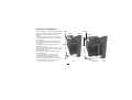
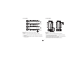
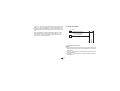
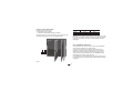
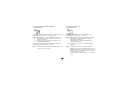
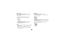
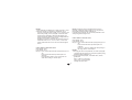
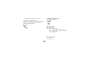
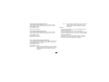
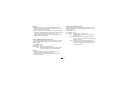
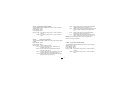
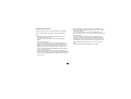
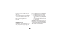
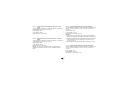
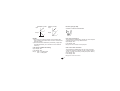
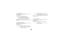
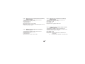
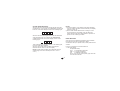
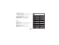
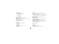
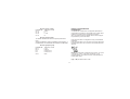
MOUNTING REQUIREMENTS
Screw
Select a location, for instrument mounting, where
minimum vibrations are present and the ambient
temperature is within 0 and 50 °C (32 and
122 °F).
The instrument can be mounted on a panel up to
15 mm thick with a cutout of 92 x 45 mm (PKC) or
92 x 92 (MKC).
For outline and cutout dimensions refer to Fig. 2.
The surface texture of the panel must be better
than 6,3 µmm.
brackets
The instrument is shipped with rubber panel
gasket (50 to 60 Sh).
To assure the IP65 and NEMA 4 protection, insert
the panel gasket between the instrument and the
panel as shown in fig. 1.
While holding the instrument against the panel
proceed as follows:
1) insert the gasket in the instrument case;
2) insert the instrument in the panel cutout;
3) pushing the instrument against the panel;
4) insert the mounting brackets as shown in fig.1;
Screw
5) with a screwdriver, turn the screws with a
torque between 0.3 and 0.4 Nm.
bracket
Gasket
Panel
Gasket
Screws
Fig. 1
GB
1
bracket
Panel
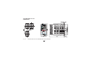
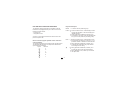
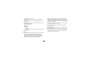
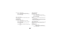
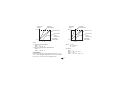
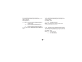
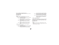
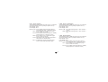
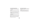
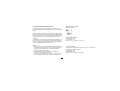
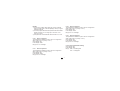
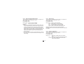
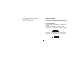
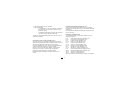
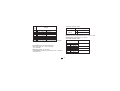
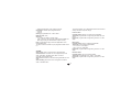
OUTLINE AND CUT OUT
DIMENSIONS
Fig. 2.A
OUTLINE AND CUT-OUT DIMENSIONS FOR PKC MODEL
GB 2
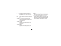
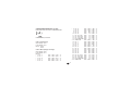
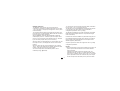
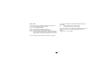
Fig. 2.B
OUTLINE AND CUT-OUT DIMENSIONS FOR MKC MODEL
GB
3
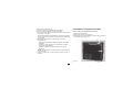
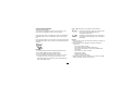
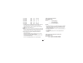
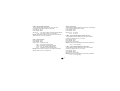
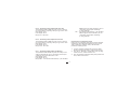
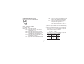
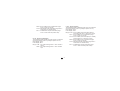
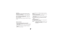
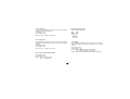
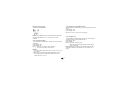
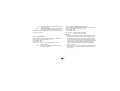
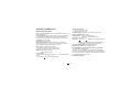
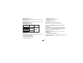
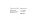
Connections are to be made with the instrument housing
installed in its proper location.
CONNECTION DIAGRAMS
A) MEASURING INPUTS
NOTE: Any external component (like zener barriers etc.)
connected between sensor and input terminals may cause
errors in measurement due to excessive and/or not balanced
line resistance or possible leakage currents.
Fig. 3
REAR TERMINAL BLOCK
GB 4
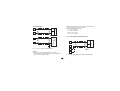
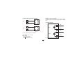
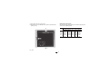
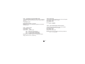
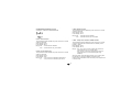
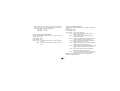
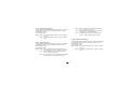
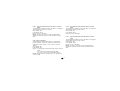
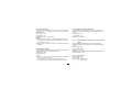
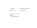
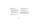
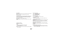
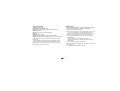
A.1) TC INPUT
A.2) RTD INPUT
+ 1
RTD
RTD
_ 3
Shield
+ 1
_ 3
4
3
1
4
3
1
Shield
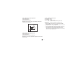
Fig. 4 THERMOCOUPLE INPUT WIRING
NOTES:
1) Don’t run input wires together with power cables.
2) For TC wiring use proper compensating cable preferable
shielded.
3) When a shielded cable is used, it should be connected at
one point only.
GB
Fig. 5 RTD INPUT WIRING
NOTES:
1) Don’t run input wires together with power cables.
2) Pay attention to the line resistance; a high line resistance
may cause measurement errors.
3) When shielded cable is used, it should be grounded at one
side only to avoid ground loop currents.
4) The resistance of the 3 wires must be the same.
5
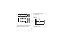
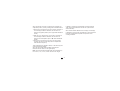
A.3) LINEAR INPUT
1
3
3) When shielded cable is used, it should be grounded at one
side only to avoid ground loop currents.
4) The input impedance is equal to:
< 5 Ω for 20 mA input
> 1 MΩ for 60 mV input
> 200 kΩ for 5 V input
> 400 kΩ for 10 V input
mA,
mV
or
_
V
+
Shield
1
3
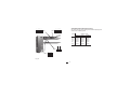
A.4) 2, 3 AND 4-WIRE TRANSMITTER INPUT
+
_
mA
mV
or
V
1
_
TX
G
3
7
Fig. 6 mA, mV AND V INPUTS WIRING
NOTES:
1) Don’t run input wires together with power cables.
2) Pay attention to the line resistance; a high line resistance
may cause measurement errors.
+
Shield
11
Fig. 7.A INPUTS WIRING FOR 2-WIRE TRANSMITTER
GB 6
1
Out
3
PWR
TX
+
7
GND
11
1
Out
+
3
Out
_
7
PWR
+
11
PWR
_
TX
Shield
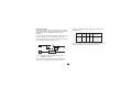
Fig. 7.C INPUTS WIRING FOR 4-WIRE TRANSMITTER
Shield
NOTES:
1) Don’t run input wires together with power cables.
2) Pay attention to the line resistance; a high line resistance
may cause measurement errors.
3) When shielded cable is used, it should be grounded at one
side only to avoid ground loop currents.
4) The input impedance is lower than 5 Ω (20 mA input)
Fig. 7.B INPUTS WIRING FOR 3-WIRE TRANSMITTER
GB
7
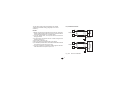
B) AUXILIARY INPUT
5
+
_
6
4) When shielded cable is used, it should be grounded at one
side only to avoid ground loop currents.
5) The input impedance is equal to:
< 5 Ω for 20 mA input
> 200 kΩ for 5 V input
> 400 kΩ for 10 V input
mA
or
V
Shield
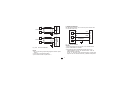
C) LOGIC INPUT
+
5
_
6
DIG. 1
8
mA
or
V
DIG. 2
9
DIG. 3
G
Fig. 8
10
AUXILIARY INPUT WIRING
NOTES:
1) This input is not isolated from measuring input. A double or
reinforced insulation between instrument output and power
supply must be assured by the external instrument.
2) Don’t run input wires together with power cables.
3) Pay attention to the line resistance; a high line resistance
may cause measurement errors.
GB 8
11
Fig. 9 - LOGIC INPUTS WIRING
NOTES:
1) Do not run logic input wiring together with power cables.
2) Use an external dry contact capable of switching 0.5 mA,
5 V DC.
3) The instrument needs 110 ms to recognize a contact status
variation.
4) The logic inputs are NOT isolated by the measuring input. A
double or reinforced insulation between instrument output
and power supply must be assured by the external element.
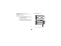
This input allows you to measure and display the current
running in the load, driven by a time proportional control output,
during the ON and OFF periods of the output cycle time. By this
feature it is also available the "Output failure detection" function
(see page 66).
NOTES:
1) This input is not isolated from measuring input. A double or
reinforced insulation between instrument output and power
supply must be assured by the external element.
2) Do not run current transformer input wiring together with AC
power cables.
3) The minimum active period to perform this measurement is
equal to 120 ms.
4) The input impedance is equal to 20 Ω.
D) CURRENT TRANSFORMER INPUT
14
Current
transformer
15
Load
Fig. 10 CURRENT TRANSFORMER INPUT WIRING
GB
9
E.1) RELAY OUTPUTS
23
OUT 1
24
25
26
OUT 2
27
28
29
The contact rating of all outputs is equal to 3A/250V AC on
resistive load.
The number of operations is 1 x 10⁵ at specified rating.
NC
C
WARNING: When OUT 3 and 4 are used as independent relay
outputs the addition of the two currents must not exceed 3 A.
NO
NOTES 1) To avoid electrical shock, connect power line at
the end of the wiring procedure.
2) For power connections use No 16 AWG or larger
wires rated for at last 75 °C.
3) Use copper conductors only.
4) Don’t run input wires together with power cables.
All relay contacts are protected by varistor against inductive load
with inductive component up to 0.5 A.
NC
C
NO
The following recommendations avoid serious problems which
may occur, when using relay output for driving inductive loads.
NO - OUT 3
OUT 3
30
C - OUT 3/4
OUT 4
31
NO - OUT 4
Fig. 11 RELAY OUTPUTS WIRING
GB 10
INDUCTIVE LOADS
High voltage transients may occur switching inductive loads.
Through the internal contacts these transients may introduce
disturbances which can affect the performance of the
instrument.
For all the outputs, the internal protection (varistor) assures a
correct protection up to 0.5 A of inductive component.
The same problem may occur when a switch is used in series
with the internal contacts as shown in Fig. 12.
The value of capacitor (C) and resistor (R) are shown in the
following table.
LOAD
(mA)
C
(µF)
R
(Ω)
P.
(W)
OPERATING
VOLTAGE
<40 mA 0.047 100
<150 mA 0.1
22
<0.5 A
0.33 47
1/2
2
2
260 V AC
260 V AC
260 V AC
Anyway the cable involved in relay output wiring must be as far
away as possible from input or communication cables.
C
R
LINE
LOAD
Fig. 12 EXTERNAL SWITCH IN SERIES WITH THE
INTERNAL CONTACT
In this case it is recommended to install an additional RC
network across the external contact as show in Fig. 12
GB 11
E.2) VOLTAGE OUTPUTS FOR SSR DRIVE
NOTE: This output is not isolated.
A double or reinforced insulation between instrument output
and power supply must be assured by the external solid state
relay.
+
24
OUT 1
_
+
_
E.3) TRIAC OUTPUTS
25
SOLID STATE
RELAY
24
Line
+
27
OUT 2
_
OUT 1
+
_
23
28
SOLID STATE
RELAY
27
Fig. 13 SSR DRIVE OUTPUT WIRING
Load
Line
OUT 2
Logic level 0: Vout < 0.5 V DC.
Logic level 1:
- 14 V + 20 % @ 20 mA
- 24 V + 20 % @ 1 mA.
Maximum current = 20 mA.
26
Fig. 14 TRIAC OUTPUT WIRING
GB 12
Load
E.4) SERVOMOTOR OUTPUT
29
30
31
12
s (Open the valve)
Power
line
Servomotor
t (Close the valve)
s (Open)
Feedback
potentiometer
Switching mode: isolated zero crossing type.
Rated current: from 50 mA to 1 A.
Rated voltage: from 24 VRMS to 240 VRMS -10 % +15 % (50/
60Hz)
Load type: resistive load only
NOTES 1) To avoid electrical shock, connect power line at
the end of the wiring procedure.
2) For power connections use No 16 AWG or larger
wires rated for at last 75 °C.
3) Use copper conductors only.
4) Don’t run input wires together with power cables.
5) This output is not fuse protected. Please, provide it
externally using a fuse with a I2t equal to128.
13
14
t (Close)
Shield
Fig. 15 SERVOMOTOR OUTPUT WIRING
GB 13
E.5) ANALOG OUTPUTS
16
OUT 5
+
+
_
_
17
Shield
16
OUT 5
+
_
17
+
_
G
Fig. 16.A OUTPUT 5 WIRING
GB 14
20 mA
NOTES:
1) Before connecting the instrument to the power line, make sure
that line voltage and the load current are in accordance with the
contact rating (3A/250V AC on resistive load).
2) To avoid electric shock, connect power line at the end of the
wiring procedure.
3) For servomotor connections use No 16 AWG or larger wires
rated for at last 75 °C.
4) Use copper conductors only.
5) Don’t run input wires together with power cables.
6) For feedback potentiometer, use shielded cable with the shield
connected to the earth at one point only.
7) The relay outputs are protected by varistor against inductive
load with inductive component up to 0.5 A.
20 mA
The two relay output must be interlocked (see chapter
"Preliminary hardware setting" paragraph "Out 3 and 4
selection").
OUT 6
F) SERIAL INTERFACE
RS-485 interface allows you to connect up to 30 devices with
one remote master unit.
+
+
_
_
19
20 mA
18
I
N
S
T
R
U
M
E
N
T
Shield
OUT 6
_
19
+
_
20 mA
18
+
G
22
21
20
A/A'
A'/A
B/B'
B'/B
COMMON
M
A
S
T
E
R
Fig. 17 - RS-485 WIRING
NOTES:
1) The cable length must not exceed 1.5 km at 9600 BAUD.
2) This serial interface is isolated.
3) The following report describes the signal sense of the
voltage appearing across the interconnection cable as
defined by EIA for RS-485.
a) The ” A ” terminal of the generator shall be negative with
respect to the ” B ” terminal for a binary 1 (MARK or OFF) state.
Fig. 16.B OUTPUT 6 WIRING
NOTE:
1) Do not run analog output wirings together with AC power
cables.
2) Out 5 and 6 are isolated outputs.
3) The maximum load is equal to 600 Ω.
GB 15
G) POWER LINE WIRING
N (L2)
33
POWER LINE 100 V to
240 V A.C (50/60Hz)
or 24 V AC/DC
L (L1)
Neutral
32
Line
b) The ” A ” terminal of the generator shall be positive with
respect to the ” B ” terminal for a binary 0 (SPACE or ON).
4) The EIA standard establishes that by RS-485 interface it is
possible to connect up to 30 devices with one remote master
unit.
The serial interface of these instruments is based on “High
input impedance” transceivers; this solution allows you to
connect up to 127 devices (based on the same transceiver
type) with one remote master unit.
Fig. 18 POWER LINE WIRING
NOTES:
1) Before connecting the instrument to the power line, make sure
that line voltage corresponds to the description on the identification label.
2) To avoid electrical shock, connect power line at the end of the
wiring procedure.
3) For supply connections use No 16 AWG or larger wires rated for
at least 75 °C.
GB 16
4)
5)
6)
7)
Use copper conductors only.
Don’t run input wires together with power cables.
For 24 V DC the polarity is a not care condition.
The power supply input is fuse protected by a sub miniature
fuse rated T, 1A, 250 V.
When fuse is damaged, it is advisable to verify the power supply
circuit, so that it is necessary to send back the instrument to
your supplier.
8) The safety requirements for Permanently Connected
Equipment say:
- a switch or circuit-breaker shall be included in the building
installation;
- it shall be in close proximity to the equipment and within
easy reach of the operator;
- it shall be marked as the disconnecting device for the
equipment.
NOTE: a single switch or circuit-breaker can drive more than
one instrument.
9) When a neutral line is present please connect it to the 32
terminal.
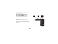
PRELIMINARY HARDWARE SETTINGS
How to remove the instrument from its case
1) Switch off the instrument.
2) Push gently the lock A on the right.
3) While the lock A is maintained out, slide out the right side of
the instrument (see fig. 19.a)
B
A
Fig. 19.a
GB 17
B
4) Push gently the lock C on the left.
5) While the lock C is maintained out, slide out the instrument
(see fig. 19.b)
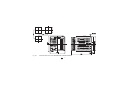
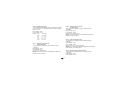
MAIN INPUT SELECTION
Set J103 (see fig. 20) according to the desired input type as
shown in the following table.
J103
D
1-2
3-4
5-6
7-8
5-7
6-8
C
D
Fig. 19.b
GB 18
INPUT TYPE
T/C, RTD
open
open
open
open
close
close
60 mV
open
open
open
open
close
close
5V
close
close
open
open
open
open
10 V
open
close
open
open
close
open
20 mA
open
open
close
close
open
open
1
3
5
7
J102
2
4
6
1
3
2
4
5
7
6
8
AUXILIARY INPUT SELECTION (option)
Set J102 (see fig. 20) according to the desired input type as
shown in the following table.
J103
8
J102
CPU
card
1-2
3-4
5-6
7-8
5-7
6-8
J205
ON
DIP
V301
1 2 3 4
Fig. 20
GB 19
INPUT TYPE
5V
close
close
open
open
open
open
10 V
open
close
open
open
close
open
20 mA
open
open
close
close
open
open
OUTPUT 3 AND 4 SELECTION
Output 3 and 4 can be set as:
- 2 independent relay outputs
- 1 servomotor output with interlocked contact.
Set J204 (see fig. 21) and J205 (see fig. 20) according to the
desired output type as shown in the following table.
Output
Relay
Servo
J 204
close
open
J 205
open
close
NOTE: when the servomotor close loop or the servomotor open
loop with valve position indication outputs is required, it will be
necessary to set also V301 (see "IN CT/Feedback selection"
paragraph)
IN CT / FEEDBACK SELECTION
This instrument can use the "IN CT" input or the "Feedback"
input; the two inputs are not contemporarily.
The current transformer input allows you to measure and
display the current running in a load driven by a time proportional control output during the ON and OFF periods of the
output cycle time. By this feature it is also available the "Out
failure detection" function (see page 66).
The feedback input is used when the servomotor close loop or
the servomotor open loop with valve position indication outputs
is required.
J204
Fig.21
GB 20
To select the desired input type, set V301 (see fig. 20) as
detailed in the following table:
Input
V301.1 V301.2
IN CT
ON
OFF
Feedback
OFF
ON
V301.3 V301.4
ON
ON
OFF
ON
ON
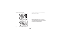
KY101
OPTION CHECK
This instrument can be supplied with many options.
Two integrated circuits (KY101 and KY103), located as shown
in fig. 22 and inserted in a socket, give you the possibility to
verify if your instrument is equipped with the desired option.
When KY101 is present the auxiliary input and the digital inputs
are present.
When KY103 is present the auxiliary power supply option is
present.
Fig. 22
GB 21
KY103
DIP
1 2 3 4
V101
Operative mode and Hardware lock
1) By V101 (see fig 22) it is possible to select one of the
following operative modes:
a) run time mode without configuration mode
b) run time and configuration modes
c) security code setting mode
Set V101 according to the following table:
Modes
a
b
c
SECURITY CODE SETTING MODE
General notes
The instrument parameters are divided in two families and
each family is divided in groups.
- The first family encompasses all the run time parameters.
- The second family comprises all the configuration
parameters.
A specific security code enables the parameter modification
of each family.
For run time parameters, it is possible to select which groups
of them will be protected by the security code and in this case
it is necessary to set the run time security code before to
modify one or more parameters of a protected group.
The configuration security code protects all configuration
parameters and it will be necessary to set the configuration
security code before to start the configuration parameters
modification.
For configuration parameters an hardware lock is also
available.
V101.1 V101.2 V101.3 V101.4
OFF
ON
ON
ON
OFF
ON
OFF
ON
OFF
ON
OFF
OFF
2) When run time mode is selected (mode a or b), V101.3
allows you to activate/deactivate the hardware lock for
configuration parameters.
If V101.3 is ON, the lock is activated.
If V101.3 is OFF, the lock is deactivated.
When the lock is activated, no one of the configuration
parameter can be modifyed.
3) All the others switch combinations are reserved.
GB 22
Run time security code
The display will show:
Security code setting:
1) Remove the instrument from its case.
2) Set the internal dip switch V101 as follows:
- V101.1 = OFF
- V101.2 = ON
- V101.3 = OFF
- V101.4 = OFF
3) Re-insert the instrument.
4) Switch on the instrument. The display will show:
The upper display shows that the security code setting mode
is selected while the lower display shows the firmware
version.
5) Push the FUNC pushbutton.
GB 23
Note: the middle display shows the current status of the run
time security code ("0", "1" or "On").
By s and t push-button, set "S.run" parameter as follows:
0
No protection (it is ever possible to modify all run time
parameters);
1
ever protected (it is never possible to modify a run
time parameter);
from 2 to 250 security code for run time parameter
protection.
NOTES:
1) the selected value of a security code cannot be displayed
anymore and, coming back to the "S.run" parameter, the
display will show "On" when "S.run" is different from 0 or 1,
"0" when "S.run" is equal to 0, "1" when "S.run" is equal to 1.
When the security code is forgotten, a new value can be set.
2) When "S.run" is different from 0 or 1, the "run time default "
and the "run time hidden" groups are ever protected by
security code.
Run time groups protected by security code
The display will show:
Configuration security code
The display will show:
By this parameter it is possible to set if the run time group 1 will
be protected or not by the run time security code.
By s and t push-button, set "Gr1" parameter as follows:
nO
No protection (it is always possible to modify run time
group 1 parameters)
Yes the run time group 1 parameter modification will be
protected by security code.
Push the FUNC push-button; the instrument memorizes the
new setting and goes to the next parameter.
Note: the middle display shows the actual status of the
configuration security code ("0", "1" or "On").
By s and t push-button, set "S.CnF" parameter as follows:
0
No protection (it is ever possible to modify all
configuration parameters);
1
ever protected (it is never possible to modify a
configuration parameter);
from 2 to 250 security code for configuration parameter
protection.
NOTE: the above described selection may be repeated for all
groups of the run time mode.
NOTE: the selected value of a security code cannot be
displayed anymore and, coming back on the "S.CnF"
parameter, the display will show "On" when "S.CnF" is
different from 0 or 1, "0" when "S.CnF" is equal to 0,
"1" when "S.CnF" is equal to 1.
When the security code is forgotten, a new value can
be set.
GB 24
RUN TIME AND CONFIGURATION MODES
Keyboard description
The hardware selection described in "Operative mode and
hardware lock" paragraph allows you to start one of the two
following operative modes:
- run time mode
- configuration mode.
MENU
FUNC = o when the instrument is in "normal display mode" it
changes the indication on the lower display (see
"display function").
o During parameter modification, it allows you to
memorize the new value of the selected parameter
and go to the next parameter (increasing order).
At power up, the instrument starts in the same mode it was
prior to the power OFF.
General note about graphic symbols used for mnemonic
code visualization.
The instrument displays some characters with special symbols.
The following table shows the correspondence between the
symbols and the characters
symbol
character
k
" "
" "
"
m
"
V
" "
W
" "
Z
"
J
"
= is used to select a parameter group
GB 25
MAN = o when the instrument is in "normal display mode",
pushing MAN push-button for more than 1 s, it is
possible to enable or disable the manual function.
o During parameter modification, it allows you to
scroll back the parameters and groups without
memorizing the new setting.
s
= o During parameter modification, it allows you to
increase the value of the selected parameter
o During MANUAL mode, it allows you to increase
the output value.
t
RSP
= o During parameter modification, it allows you to
decrease the value of the selected parameter
o During MANUAL mode, it allows to decrease the
output value.
= allows to toggle from Local set point to Remote set
point or viceversa when depressed for more than 1
sec.
t+MENU= are used to start the lamp test function (the
command is accepted when push-button are kept
depressed for more than 5 s and device is in
normal display mode)
s+FUNC or t+FUNC
During parameter modification they allow you to
increase/decrease the value under modification
with higher rate.
s+MAN or t+MAN
During parameter modification they allow you to
jump to the max or min programmable value.
GB 26
NOTES:
1) All the actions explained above which requires two or more
push-buttons must follow exactly the push-button sequence
shown.
2) A 10 or 30 seconds time out (see "t.out" [C.I10]) can be
selected for parameter modification during run time mode.
If, during parameter modification, no push-button is
depressed for more than 10 (30) seconds, the instrument
goes automatically to the “normal display mode” and the
eventual modification of the last parameter will be lost.
By s or t push-button it is possible to select between:
CONFIGURATION MODE
Switch on the instrument.
The instrument will start in the same way it was prior to the
power down (configuration mode or run time mode)
If the instrument starts in configuration mode, push the MENU
pushbutton and go to the "Configuration group 1" (see page
30).
If the instrument starts in run time mode, by keeping depressed
the MENU push-button for more than 5 seconds the instrument
will show:
NOTES:
1) The upper display shows the selected parameter family.
2) The middle display shows the selected action.
3) The lower display shows the firmware version.
4) If no push-button is depressed for more than 10 s (or 30 s
according to "CnF.6" "t.out" [time out selection" C.I10]
parameter setting), the instrument returns automatically to
the normal display mode.
GB 27
=
(monitor) this selection allows you to monitor but
not to modify the value assigned to the
configuration parameters
=
(modify) this selection allows you to monitor and
to modify the value assigned to the configuration
parameters.
NOTES:
1) During monitor mode, the instrument continues to operate as
in run time mode.
2) When modify mode is started, the instrument stops the
control and:
- sets control outputs to OFF;
- turns OFF the bargraph displays (MKC only);
- sets analog retransmissions to the retransmitted initial
scale value;
- sets alarms in no alarm condition;
- sets events to OFF;
- disables the serial link;
- the time out will be removed.
3) When the modify mode is disabled by V101 (V101.3), the s
or t push-button pressure has no effect.
MONITOR MODE
During the run time mode, it is possible to monitor but not
modify all configuration parameters.
When it is desired to verify the instrument configuration,
proceed as follows:
MODIFY MODE
1) By s or t push-button select the modify mode.
2) Push the MENU push-button.
If a security code is applied to the configuration parameter,
the instrument will show:
1) By s or t push-button select the monitor mode.
2) Push the MENU push-button the display will show:
3) By s and t push-button set a value equal to the security
code assigned to the configuration mode (see "Configuration
security code " at page 24).
If the code is different from the security code, the instrument
automatically returns to the first configuration display
otherwise the display will show:
it shows that configuration group 1 is selected and it
encompass all the input parameters.
The configuration parameter "Monitor mode" follows the
"Modify mode" sequence.
NOTES:
1) During monitor mode, the instrument continues to operate as
in run time mode.
2) During monitor mode, if no push-button is depressed for
more than 10 s (or 30 s according to "t.out" [C.I10]
parameter setting), the instrument returns automatically to
the normal display mode.
GB 28
The modify mode is started.
This display allows you to load the default configuration
parameter.
For more details see chapter "Default parameter" (see
Appendix A).
4) By s or t push-button select the OFF indication and push
the MENU push-button.
The display will show:
This is the starting display of the first group of configuration
parameters.
NOTES:
1) In the following pages we will describe all the parameters of
the instrument but the instrument will show only the
parameters related with the specific hardware and in
accordance with the specific instrument configuration (i.e.
setting OUT 3 different from servo, all the parameters
related with servomotor output will be skipped).
GB 29
2) During configuration parameters modify mode, the upper
display shows the selected parameter group, the lower
display shows the mnemonic code of the selected parameter
while the central display shows the value or status assigned
to the selected parameter.
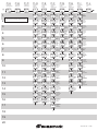
3) For an easy consultation of this manual, a table with all the
parameter visualizations is enclosed.
When it is desired to exit from configuration modify mode
proceed as follows:
a) Push "MENU" push-button until the "Configuration group
END is displayed.
b) Pushing ”s” or “t” push-button select the "YES" indication.
c) Push “MENU” push-button. The instrument terminates the
configuration modify mode, it preforms an automatic reset
and restarts in the run time mode.
* 6 = TC E
7 = TC N
8 = TC S
9 = TC R
10 = TC B
11 = TC G (or W)
12 = TC D (or W3)
13 = TC C (or W5)
14 = TC Ni-Ni18%Mo
* 15 = RTD Pt100
16 = TC L
17 = TC J
18 = TC K
19 = TC T
20 = TC U
21 = TC E
22 = TC N
23 = TC S
24 = TC R
25 = TC B
26 = TC G ( or W)
27 = TC D (or W3)
28 = TC C (or W5)
29 = TC Ni-Ni18%Mo
* 30 = RTD Pt100
CONFIGURATION GROUP 1 [C.dxx]
MAIN AND AUXILIARY INPUT CONFIGURATION
Push the FUNC push-button
C.d01- Line frequency
Upper display: CnF.1
Lower display: Ln.Fr
Range: 50 Hz
60 Hz
C.d02 - Main input type and range
Upper display: CnF.1
Lower display: ñ.In.t
Ranges:
* 1 = TC L
From -100 to 900
* 2 = TC J
From -100 to 1000
* 3 = TC K
From -100 to 1370
* 4 = TC T
From -200 to 400
* 5 = TC U
From -200 to 600
°C
°C
°C
°C
°C
GB 30
From
From
From
From
From
From
From
From
From
From
From
From
From
From
From
From
From
From
From
From
From
From
From
From
From
-100
-100
- 50
- 50
0
0
0
0
0
-200
-150
-150
-150
-330
-330
-150
-150
- 60
- 60
32
0
0
0
0
-330
to
to
to
to
to
to
to
to
to
to
to
to
to
to
to
to
to
to
to
to
to
to
to
to
to
800
1400
1760
1760
1820
2300
2300
2300
1100
850
1650
1830
2500
750
1110
1470
2550
3200
3200
3300
4170
4170
4170
2000
1560
°C
°C
°C
°C
°C
°C
°C
°C
°C
°C
°F
°F
°F
°F
°F
°F
°F
°F
°F
°F
°F
°F
°F
°F
°F
31 = Linear
From
0 to
20 mA
32 = Linear
From
4 to
20 mA
33 = Linear
From
0 to
5
V
34 = Linear
From
1 to
5
V
35 = Linear
From
0 to
10
V
36 = Linear
From
2 to
10
V
37 = Linear
From
0 to
60 mV
38 = Linear
From 12 to
60 mV
* For these ranges it is possible to select a read-out with one
decimal figure but the instrument could not display a
measure lower than -199.9 or higher than 999.9 and the
input range will be limited by it.
NOTES:
1) When a linear input is selected, the instrument set automatically the "readout initial scale value" [C.d05] equal to 0 and
the "readout final scale value" [C.d06] equal to 4000
2) When input type has been changed, the instrument
automatically forces:
- the "ñ.In.L" [C.d05], "SS.th" [C.I09] and "brG.L" [C.I03]
parameters to the new initial scale value,
- the "ñ.In.H" [C.d06] and "brG.H" [C.I04] parameter to the
new final scale value and
- the "ñ.In.d" [C.d03] parameter to "no decimal figure".
GB 31
C.d03 - Decimal point position
Upper display: CnF.1
Lower display: ñ.In.d
Ranges: _ _ _ _. no decimal figure
_ _ _ . _ one decimal figure
_ _ . _ _ two decimal figures
_ . _ _ _ three decimal figures
NOTES:
1) For main input type 1 to 6, 15 and 30 only the "no decimal
figure" and "one decimal figure" are selectable, the input
range is limited within -199.9 and 999.9 and it acts as an
input type changement.
2) For main input type 7 to 14 and 16 to 29 this parameter is
not available.
3) For linear input types (from 31 to 38) all positions are
available.
C.d04 - Square root extraction for main input
Upper display: CnF.1
Lower display: ñ.In.S
Ranges: dIS = square root extraction disabled
Enb = square root extraction enabled
NOTES:
1) This parameter is available only for main input type 31 to 38.
2) When the square root extraction is enabled the "ñ.In.L"
(read-out - initial scale value [C.d05]), "ñ.In.H" (read-out - full
scale value [C.d06]), "brG.L" (bargraph - initial scale value
[C.I03]), "brG.H" (bargraph - full scale value [C.I04]) and
"SS.th" (threshold to enable the soft start [C.I09]) parameter
values must be positive or equal to zero.
Enabling the square root extraction the instrument verify the
actual value of the "ñ.In.L", "ñ.In.H", "brG.L", "brG.H" and
"SS.th" parameters and force to zero the eventual negative
values.
C.d05 - Read-out- initial scale value
Upper display: CnF.1
Lower display: ñ.In.L
Ranges: - from -1999 to 9999 for linear input (Input range 31 to
38),
- from 0 to 9999 for linear input with square root
extraction,
- from initial range value to "ñ.In.H" (read-out- full
scale value C.d06]) for TC/RTD input
GB 32
NOTE: Changing the value of this parameter, the "brG.L"
(bargraph - initial scale value [C.I03]) and "rL" (set point low
limit [r.E12]) parameters will be realigned to it.
If a linear input is selected, also the “SS.th” (threshold for soft
start [C.I09]) will be realigned to it.
C.d06 - Read-out- full scale value
Upper display: CnF.1
Lower display: ñ.In.H
Ranges: - from -1999 to 9999 for linear input (Input range 31 to
38),
- from 0 to 9999 for linear input with square root
extraction,
- from "ñ.In.L" (read-out- initial scale value [C.d05]) to
full range value for TC/RTD input.
NOTES:
1) Changing the value of this parameter, the "brG.H" (bargraph
- full scale value [C.I04]) and "rH" (set point high limit [r.E13])
parameters will be realigned to it.
2) The programmed input span, in absolute value, must be
greater than:
300 °C or 550 °F for TC inputs
100°C or 200 °F for RTD inputs
100 digits for linear inputs.
C.d09 - Auxiliary input function
Upper display: CnF.1
Lower display: A.In.F
Range: nonE = Input not used
rSP = Input used as remote set point input
bIAS = Input used as bias for local set point
NOTES:
1) When auxiliary input option is not mounted the middle
display will show “no.Pr” (not present).
2) The parameter “L.r.O.ñ” [C.d16] will be forced to “n.ALG” if
“A.In.F” [C.d09]= “bIAS” and “A.I.Añ” [C.d14]= “Cnd.A”.
3) When "bIAS" is selected, the instrument uses as operative
set point the sum of the local set point with the value
measured by the auxiliary input scaled by "A.In.L" [C.D11]
and "A.In.H" [C.d12] parameters.
C.d07 - Main input - offset adjustment.
Upper display: CnF.1
Lower display: OFSt
Ranges: from -500 to 500.
NOTE: the decimal point will be automatically positioned as
selected for the main input.
Read-out
OFSt
Real curve
Adjusted
curve
Input
C.d08 - Filter on the displayed value
Upper display: CnF.1
Lower display: dS.FL
Ranges: from 0 (no filter) to 8 seconds.
NOTE: this is a first order digital filter applied to the read-out of
the main input.
GB 33
C.d10 - Auxiliary input type
This parameter will be skipped when the auxiliary input option
is not mounted or "A.In.F" (auxiliary input function [C.d09]) is
equal to "nonE".
Upper display: CnF.1
Lower display: A.In.t
Range: 0-20
= 0−20 mA
4-20
= 4−20 mA
0- 5
= 0− 5 V
1- 5
= 1− 5 V
0-10
= 0−10 V
2-10
= 2−10 V
C.d12 - Auxiliary input read-out full scale value
This parameter is available only when auxiliary input is
configured
Upper display: CnF.1
Lower display: A.In.H
Range: from -1999 to 9999
NOTE: the decimal point will be automatically positioned as
selected for the main input.
C.d13 - Filter on auxiliary input
This parameter is available only when auxiliary input is
configured
Upper display: CnF.1
Lower display: A.I.FL
Ranges: from 0 (no filter) to 8 seconds.
NOTE: this is a first order digital filter applied to the measured
value made by the auxiliary input.
C.d11 - Auxiliary input read-out Initial scale value
This parameter is available only when auxiliary input is
configured
Upper display: CnF.1
Lower display: A.In.L
Range: from -1999 to 9999
NOTE: the decimal point will be automatically positioned as
selected for the main input.
C.d14 - Auxiliary input activation mode
This parameter is available only when auxiliary input is
configured
Upper display: CnF.1
Lower display: A.I.Añ
GB 34
Range: norñ = The auxiliary input activation is controlled by
external contact, front key or serial link
Cnd.A= The auxiliary input activation is controlled by its
status (The device works with local set point
when auxiliary input is out of range, while it
works with remote set point (or bias) when it is
within range)
NOTE: The parameter “L.r.O.ñ” (local/remote set point
operative mode [C.d16]) will be forced to “n.ALG” if “A.In.F”
(auxiliary input function [C.d09]) is equal to “bIAS” and “A.I.Añ”
(auxiliary input activation mode [C.d14]) is equal to “Cnd.A”.
C.d15 - Auxiliary input safety condition
This parameter is available only when auxiliary input is
configured and "A.i.Añ" [C.d14] is equal to "norñ".
Upper display: CnF.1
Lower display: A.I.Sc
Range: nonE = when the auxiliary input is out of range, the
instrument operates as in presence of the min
or max auxiliary input value.
Cnd.A = when the auxiliary input is out of range, the
control output goes to safety value “SF.UL”
(output safety value [C.G08]).
GB 35
If servomotor open loop control drive is
configured the “Safety value” "SF.UL" [C.G08]
has no effect and the instrument operates in
accordance with “SF.Cn” (Output safety
condition [C.G07]) parameter setting.
NOTE: The “SF.Cn” (Output safety condition” [C.G07]) has the
priority on “A.I.Sc” (auxiliary input safety condition [C.d15]).
C.d16 - Local/remote set point operative mode
This parameter is available only when auxiliary input is
configured
Upper display: CnF.1
Lower display: L.r.O.ñ
Range: ALG = when the transfer from remote to local set
point is performed, the local set point value will
be aligned to last remote set point value.
n.ALG = when the transfer from remote to local set
point is performed, the local set point value will
not be changed (The programmed ramps Grd1
[r.E14] and Grd2 [r.E15] may be activated).
NOTES:
1) The selected local set point will be changed even if it is
software protected.
2) The parameter is forced to “n.ALG” if “A.In.F” (auxiliary input
function [C.d09]) is equal to “bIAS” and “A.I.Añ” (auxiliary
input activation mode [C.d14]) is equal to “Cnd.A”
CONFIGURATION GROUP 2 [C.Exx]
OUTPUTS CONFIGURATION
General note on configuration group 1
Exiting from the configuration group 1 the instrument verifies
automatically the programmed span for the linear input.
If it is wrong, the device will show:
C.E01 - OUT 1 function
Upper display: CnF.2
Lower display: O1.Fn
Range: nonE = Output not used
ñAin = Time proportional main control output
SECn = Time proportional secondary control output
ALr.1 = Alarm 1 output
Eun.1 = Event 1 output
C.E02 - OUT 2 function
Upper display: CnF.2
Lower display: O2.Fn
GB 36
Range: nonE
ñAin
SECn
ALr.2
Eun.2
= Output not used
= Time proportional main control output
= Time proportional secondary control output
= Alarm 2 output
= Event 2 output
C.E03 - OUT 3 function
When the option is not mounted the middle display will show
“no.Pr” (not present).
Upper display: CnF.2
Lower display: O3.Fn
Range: nonE = Output not used
ñAin = Time proportional main control output
SECn = Time proportional secondary control output
ALr.3 = Alarm 3 output
Eun.3 = Event 3 output
ñC.Sñ = Servomotor control drive as main control
output
SC.Sñ = Servomotor control drive as secondary control
output
GB 37
C.E04 - OUT 4 function
Upper display: CnF.2
Lower display: O4.Fn
Range: nonE = Output not used
ñAin = Time proportional main control output
SECn = Time proportional secondary control output
ALr.4 = Alarm 4 output
Eun.4 = Event 4 output
NOTES:
1) When option is not mounted the middle display will show
“no.Pr” (not present).
2) When servomotor control drive is hardware selected (see
"Output 3 and 4 selection" at pag. 20), the OUT 4 can be
used only as servomotor drive.
C.E05 - Servomotor type
This parameter will be available only when servomotor control
drive is configured (“CnF.2 - O3.Fn” [C.E03]= “ñC.Sñ” or
“SC.Sñ”).
Upper display: CnF.2
Lower display: Sñ.tP
Range: CLSd = Close loop type
NOTE: this selection is available only if
feedback circuitry is mounted and selected.
OPEn = Open loop type
C.E06 - Valve position indication
This parameter will be displayed only when open loop
servomotor control drive output is confi-gured.
Upper display: CnF.2
Lower display: FEEd
Range: Fb
= The valve position is measured and displayed
no.Fb = The valve position is not measured
NOTE: If the feedback option is not mounted, this parameter
will be forced to “no.Fb” (no feedback).
C.E07 - OUT 5 function
Upper display: CnF.2
Lower display: O5.Fn
Range: nonE = Output not used
ñAin = Main control output (linear)
SECn = Secondary control output (linear)
PV.rt = Process variable retransmission
SP.rt = Operative set point retransmission
NOTE: When the option circuitry is not mounted the middle
display will show “no.Pr” (not present).
C.E08 - OUT 5 range
This parameter will be available only when Out 5 is configured
("O5.Fn" [C.E07] different from "nonE")
Upper display: CnF.2
Lower display: O5.rn
Range: 0-20 = 0÷20 mA
4-20 = 4÷20 mA
C.E09 - OUT 5 retransmission initial scale value
This parameter will be available only when Out 5 function
[C.E07] is configured as “PV.rt” or “SP.rt”
Upper display: CnF.2
Lower display: O5.Lr
Range: From -1999 to 9999
NOTE: Decimal point is positioned as previously selected at
“CnF.1 - ñ.In.d” [C.d03])
C.E10 - OUT 5 retransmission full scale value
This parameter will be available only when Out 5 function
[C.E07] is configured as “PV.rt” or “SP.rt”
Upper display: CnF.2
Lower display: O5.Hr
Range: From -1999 to 9999
NOTE: Decimal point is positioned as previously selected at
“CnF.1 - ñ.In.d” [C.d03])
GB 38
C.E11 - OUT 5 filter on the retransmitted value
This parameter will be available only when OUT 5 is configured
as process variable retransmission ("O5.Fn" [C.E07] is equal to
“PV.rt”).
Upper display: CnF.2
Lower display: O5.FL
Range: From 0 (no filter) to 8 seconds
NOTE: this is a first order digital filter applied to the retransmitted output value.
C.E13 - OUT 6 range
This parameter will be available only when Out 6 is configured
("O6.Fn" [C.E12] different from "nonE")
Upper display: CnF.2
Lower display: O6.rn
Range: 0-20 = 0÷20 mA
4-20 = 4÷20 mA
C.E14 - OUT 6 retransmission initial scale value
This parameter will be available only when Out 6 function
[C.E12] is configured as “PV.rt” or “SP.rt”
Upper display: CnF.2
Lower display: O6.Lr
Range: From -1999 to 9999
NOTE: Decimal point is positioned as previously selected at
“CnF.1 - ñ.In.d” [C.d03].
C.E12 - OUT 6 function
Upper display: CnF.2
Lower display:
O6.Fn
Range: nonE = Output not used
ñAin = Main control output (linear)
SECn = Secondary control output (linear)
PV.rt = Process variable retransmission
SP.rt = Operative set point retransmission
NOTE: When the option circuitry is not mounted the middle
display will show “no.Pr” (not present).
GB 39
General note on configuration group 2
I) Exiting from the configuration group 2 the instrument verifies
automatically the congruence of all parameters. If a wrong
setting is detected, the device will show:
C.E15 - OUT 6 retransmission full scale value
This parameter will be available only when Out 6 function
[C.E12] is configured as “PV.rt” or “SP.rt”
Upper display: CnF.2
Lower display: O6.Hr
Range: From -1999 to 9999
NOTE: Decimal point is positioned as previously selected at
“CnF.1 - ñ.In.d” [C.d03])
C.E16 - OUT 6 filter on the
retransmitted value
This parameter will be available only when OUT 6 is configured
as process variable retransmission ("O6.Fn" [C.E12] is equal to
“PV.rt”).
Upper display: CnF.2
Lower display: O6.FL
Range: From 0 (no filter) to 8 seconds
NOTE: this is a first order digital filter applied to the retransmitted output value.
The group 2 parameter passes the congruence test when:
1) Only one of the 6 outputs is configured as main output
(“ñAin”)
2) Only one of the 6 outputs is configured as secondary
output (“SECn”)
3) If only one control output is configured, it should be the
main control output (“ñAin”)
4) The servomotor must be “close loop” type if it is one of
two control outputs.
NOTE: The instrument may be used as an indicator, so that this
test is satisfied even if no output is configured as control output
II) Exiting from the configuration group 2 also the following
actions are automatically performed:
A) The "Añ.UL” parameter ("Output value for auto to manual
GB 40
transfer" [C.G04]) will be forced to "bumpless" (“buñ”) if:
1) its value is < 0 and only one control output is configured;
2) servomotor open loop without feedback is configured.
B) The parameter “SF.Cn” ("Condition for output safety value"
[C.G07]) will be forced to "standard" (“Std.”) if it is not
complied with configured control output type
C) The parameter “SF.UL” ("Output safety value" [C.G08]) will
be forced to 0 if only one control output is configured and its
value is < 0.
D) The parameter “Fd.Fn” ("Out failure detection current
measurement" [C.I11]) will be forced to “nonE” if it is
assigned to a control output different from a time
proportional output.
E) The parameter “Fd.Ou” ("Out failure detection output
assignment" [C.I13]) will be forced to “nonE” if it is
assigned to an output configured as control output
F) The parameter “IP” ("Integral pre-load" [r.d05]) will be forced
to 50.0 if only one control output is configured and its value
is < 0
GB 41
CONFIGURATION GROUP 3 [C.Fxx]
CONTROL OUTPUT CONFIGURATION
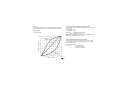
C.F01 - Split range
This parameter will be available only when two control outputs
are configured.
Upper display: CnF.3
Lower display: SPLt.
Range: dIS
= Split range feature is not required
Enb = Split range feature is required
NOTE about the split range.
This function allows you to drive by the same control action,
two physical outputs (two actuators) with different bias and
gain.
The relation between the Calculated Power Output and the
resulting real outputs are shown below:
Real PWR
Output
Real PWR
Output
First split
output (MAIN)
First split
output (MAIN)
100 %
100 %
0%
A
C
B
Standard curve
Standard curve
Second split
output
(Secondary)
Second split
output
(Secondary)
Calculated
100 % PWR Output
D
Calculated
100 % PWR Output
0%
33.3 %
where:
- for the first split output (MAIN)
Bias 1 = -A
Gain 1 = 100 / (B - A)
- For the second split output (SECONDARY)
Bias 2 = -C
Gain 2 = 100 / (D - C)
Where: A = 0 %
B = C = 33.3 %
D = 100 %
FOR EXAMPLE:
Let's suppose that the first split output operates from 0 % to
33.3 % of the calculated output while the second one operates
from 33.3 % to the 100 % of the calculated output.
GB 42
We will set:
Bias 1 = 0
Gain 1 = 100 / (33.3 - 0) = 3
Bias 2 = - 33.3
Gain 2 = 100 / (100 - 33.3) = 1,5
The bias and gain of the two split outputs are the following:
“ñC.bS” [C.F03] is the Bias 1 applied to the main output
“ñC.Gn” [C.F02] is the Gain 1 applied to the main output
“SC.bS” [C.F05] is the Bias 2 applied to the secondary output
“SC.Gn” [C.F04] is the Gain 2 applied to the secondary output
C.F02 - Main control output gain
This parameter will be available only when the split range is
enabled ("SPLt." [C.F01] = "Enb").
Upper display: CnF.3
Lower display: ñC.Gn
Range: from 0.50 to 5.00.
C.F05 - Secondary control output bias
This parameter will be available only when the split range is
enabled ("SPLt." [C.F01] = "Enb").
Upper display: CnF.3
Lower display: SC.bS
Range: from -100.0 to 100.0 % of the output span.
C.F06 - Main control output conditioning
This parameter will be available only when main control output
is configured.
Upper display: CnF.3
Lower display: ñC.Cn
Range: norñ = The control output is calculated by the PID
CñPL = The control output is complemented (100-PID
calculated value)
Ouic = The control output is conditioned to match a
“QUICK OPENING” flow characteristic
Eou = The control output is conditioned to match an
“EQUAL PERCENTAGE” flow characteristic
C.F03 - Main control output bias
This parameter will be available only when the split range is
enabled ("SPLt." [C.F01] = "Enb").
Upper display: CnF.3
Lower display: ñC.bS
Range: from -100.0 to 100.0 % of the output span.
C.F04 - Secondary control output gain
This parameter will be available only when the split range is
enabled ("SPLt." [C.F01] = "Enb").
Upper display: CnF.3
Lower display: SC.Gn
Range: from 0.50 to 5.00
NOTE about output conditioning
Sometimes non linear valves are used where a linear valve is
suitable.
In these cases, it is advisable to linearize the ratio between flow
rate and valve travel in order to obtain a better control of the
GB 43
process.
This instrument allows you to select an output linearization in
accordance with the two most common valve flow characteristics:
- Quick opening
- Equal percentage.
C.F07 - Main control output in engineering unit
This parameter will be available only when main control output
is configured.
Upper display: CnF.3
Lower display: ñ.SCL
Range: nO
= Scalable is not required
YES = Scalable is required
NOTE: This scaling allows you to display the output value in
engineering units instead of in percent.
C.F08 - Main output decimal point position
This parameter will be available only when "ñ.SCL" ("Main
control output in engineering units" [C.F07]) is set to "yES".
Upper display: CnF.3
Lower display: ñC.dP
Range: ——.
= No decimal figure
—.= One decimal figure
—.—
= Two decimal figures
GB 44
AFtr
C.F09 - Main output initial scale value
This parameter will be available only when "ñ.SCL" ("Main
control output in engineering units" [C.F07]) is set to "YES".
Upper display: CnF.3
Lower display: ñC.E.L
Range: from -199 to 999
= The functions listed at Note (**) are calculated
after to apply the action selected by “ñC.Cn”
(“Main control output conditioning” [C.F06])
parameter.
Note (**)
- "Main control output limiters" - for more details see [r.E04]
and [r.E05] parameters.
- "Main control output max rate of rise" (see [r.E06]).
- "Control output display value" - for more details see "Display
function" paragraph at pag. 62 and [C.F07], [C.F08], [C.F09]
and [C.F10] parameters.
- "Threshold for alarm on control output value" - for more
details see [r.F01], [r.F05] [r.F09] and [r.F13] parameters.
- The control output value displayed by bargraph.
C.F10 - Main output full scale value
This parameter will be available only when "ñ.SCL" ("Main
control output in engineering units" [C.F07]) is set to "YES".
Upper display: CnF.3
Lower display: ñC.E.H
Range: from -199 to 999
C.F11 - Main output auxiliary conditioning
This parameter will be available only when main control output
is configured and “ñC.Cn” ("Main control output conditioning"
[C.F06]) is different from “norñ”.
Upper display: CnF.3
Lower display: ñC.A.C
Range: bEFr = The functions listed at Note (**) are calculated
before to apply the action selected by “ñC.Cn”
("Main control output conditioning" [C.F06])
parameter.
GB 45
C.F12 - Secondary control output conditioning
This parameter will be available only when secondary control
output is configured.
Upper display: CnF.3
Lower display: SC.Cn
Range: norñ = The control output is calculated by the PID
CñPL = The control output is complemented (100-PID
calculated value)
Ouic = The control output is conditioned to match a
“QUICK OPENING” flow characteristic
Eou = The control output is conditioned to match an
“EQUAL PERCENTAGE” flow characteristic
For more details see also NOTE about output conditioning at
page 43.
GB 46
C.F13 - Secondary control output in engineering unit
This parameter will be available only when secondary control
output is configured.
Upper display: CnF.3
Lower display: S.SCL
Range: nO
= Scalable is not required
YES = Scalable is required
NOTE: This scaling allows to display the output value in
engineering units instead of in percent.
C.F14 - Secondary control output decimal point position
This parameter will be available only when "S.SCL" ("Secondary control output in engineering units" [C.F13]) is set to "YES".
Upper display: CnF.3
Lower display: SC.dP
Range: ——. = No decimal figure
—.- = One decimal figure
—.— = Two decimal figures
C.F15 - Secondary control output initial scale value
This parameter will be available only when "S.SCL" ("Secondary control output in engineering units" [C.F13]) is set to "YES".
Upper display: CnF.3
Lower display: SC.E.L
Range: from -199 to 999
C.F16 - Secondary control output full scale value
This parameter will be available only when "S.SCL" ("Secondary control output in engineering units" [C.F13]) is set to "YES".
Upper display: CnF.3
Lower display: SC.E.H
Range: From -199 to 999
AFtr
General note on configuration group 3
Exiting from the configuration group 3 the instrument automatically tests the "SPLt" parameter (Split range [C.F01]). When
"SPLt." parameter is enabled (= "Enb"), the instrument
performs the following actions:
1)
C.F17 - Secondary output auxiliary conditioning
This parameter will be available only when secondary control
output is configured and “SC.Cn” ("Secondary control output
conditioning" [C.F12]) is different from “norñ”.
Upper display: CnF.3
Lower display: SC.A.C
Range: bEFr = The functions listed at Note (**) are calculated
GB 47
before to apply the action selected by “SC.Cn”
("Secondary control output conditioning"
[C.F12]) parameter.
= The functions listed at Note (**) are calculated
after to apply the action selected by “SC.Cn”
(“Secondary control output conditioning”
[C.F12]) parameter.
2)
3)
If “Añ.UL” parameter ("Output value for AUTO to MAN
transfer [C.G04]) is lower than 0, it will be forced to “buñ“.
If the “SF.UL” parameter ("Output safety value" [C.G08])
is lower than zero, it will be forced to zero.
If the “IP” parameter ("Integral pre-load" [r.d05] is lower than
zero, it will be forced to 50.0.
CONFIGURATION GROUP 4 [C.Gxx]
AUXILIARY CONTROL CONFIGURATION
C.G03 - Manual function
This parameter will be available only when at least one control
output is configured
Upper display: CnF.4
Lower display: ñAn.F
Range: dIS
= Manual function disabled
Enb = Manual function may be enabled
C.G01 - Smart function
This parameter will be available only when at least one control
output is configured
Upper display: CnF.4
Lower display: Sñ.Fn
Range: dIS
= Smart function disabled
Enb = Smart function may be enabled
C.G02 - Control action type
This parameter will be available only when at least one control
output is configured
Upper display: CnF.4
Lower display: Cn.tP
Range: Pid
= The process is controlled by PID actions
Pi
= The process is controlled by PI actions
GB 48
C.G04 - Output value for AUTO to MAN transfer
This parameter will be available only when at least one control
output is configured and manual function is enabled (“ñAn.F”
[C.G03] = “Enb”)
Upper display: CnF.4
Lower display: Añ.UL
Range: - from 0.0 to 100.0 % of the output span if device is
configured with only one control output
- from -100.0 to 100.0 of the output span if device is
configured with two control outputs (split range
excluded).
Above the value 100.0 the display shows “buñ.” meaning that
the transfer from AUTO to MANUAL is bumpless (the
instrument set for MANUAL mode the same power output used
in AUTO mode)
NOTES:
1) When open loop servomotor control drive without valve
position indication is configured, this parameter is forced to
“buñ.” and it cannot be modified.
2) When open loop servomotor control drive with valve position
indication is configured and the transfer from AUTO to MAN
is required, the instrument is able to reach the value
programmed by this parameter using temporarily the valve
position value as a feedback.
C.G05 - MANUAL to AUTO transfer type
This parameter will be available only when at least one control
output is configured and manual function is enabled (“ñAn.F”
[C.G03] = “Enb”)
Upper display: CnF.4
Lower display: ñ.A.t.t
Range: buñ. = Bumpless balance transfer
buñ.b = Bumpless balanceless transfer (the operative
set point is aligned to the measure value)
NOTES:
1) The “alignment” is not performed if measure is in error
condition or Remote Set point is selected
2) The selected local set point will be changed even if it is
software protected.
GB 49
C.G06 - Device status at start up
This parameter will be available only when at least one control
output is configured and manual function is enabled (“ñAn.F”
[C.G03] = “Enb”).
Upper display: CnF.4
Lower display: St.Fn
Range: Auto = It starts always in auto mode
ñan = It starts always in manual mode with power
output set to 0
Cnd.A = It starts in the same way it was left prior to
power shut down (if in manual mode the power
output is set to 0)
Cnd.b = It starts in the same way it was left prior to
power shut down (if in manual mode the power
output will be equal to the last value prior to
power shut down).
C.G07 - Condition for output safety value
This parameter will be available only when at least one control
output is configured.
Upper display: CnF.4
Lower display: SF.Cn
Ranges:
- When no output is configured as open loop servomotor
control, "SF.Cn" can be set as follows:
Std. = No safety value (“standard setting” see chapter
ERROR MESSAGES).
Ov.Un = Safety value applied when the instrument
detect an overrange or underrange condition of
the main input.
OvEr = Safety value applied when the instrument
detect an overrange condition of the main
input.
Undr = Safety value applied when the instrument
detect an underrange condition of the main
input.
- When the open loop servomotor control is configured,
"SF.Cn" can be set as follows:
Std. = No safety value (“standard setting” see chapter
ERROR MESSAGES).
Cnd.A = When the instrument detects an overrange or
underrange condition of the main input, the
GB 50
servomotor is driven to its high limit position.
Cnd.b = When the instrument detects an overrange or
underrange condition of the main input, the
servomotor is driven to its low limit position.
Cnd.C = When the instrument detects an overrange or
underrange condition of the main input, the
action on servomotor is the complement of
“standard” setting.
C.G08 - Output safety value
This parameter will be available only when "SF.Cn" [C.G07] is
equal to “Ov.Un”, “OvEr” or “Undr”or the parameter “A.I.Sc”
("Auxiliary input safety condition" [C.d15]) is equal to “Cnd.A”
Upper display: CnF.4
Lower display: SF.UL
Range:
- from 0.0 to 100.0 if device is configured with one control
output;
- from -100.0 to 100.0 if device is configured with two control
outputs (split range excluded).
CONFIGURATION GROUP 5 [C.Hxx]
DIGITAL INPUT/OUTPUT CONFIGURATION
Hold = Input contact used to stop input sampling (Hold
function) (Stop sampling when logic level is
“1”)
ñ.rSt = Input contact used to reset (acknowledge)
alarm (Reset when logic level is “1”)
rE.dr = Input contact used for Reverse/Direct control
action selection (Direct when logic level is “1”)
C.H01 - Logic input 1 function
Upper display: CnF.5
Lower display: d1.Fn
Range: nonE = Input contact not used
SP1.2 = Input contact used for SP /SP2 set point
selection (see note 2)
SP3.4 = Input contact used for SP3/SP4 set point
selection (see note 2)
SP.L.r = Input contact used for Local/Remote set point
selection (Remote when logic level is “1”)
Au.ñA = Input contact used for Auto/Manual selection
(Manual when logic level is “1”)
O.LIñ = Input contact used for output limiter activation
(Output limited when logic level is “1”)
GB 51
NOTES:
1) When logic input circuits are not mounted the middle display
will show “no.Pr” (not present).
2) When one logic input is set to “SP.1.2” and no other logic
input is set to “SP.3.4”, the relation between the logic level
and the selected set point is the following:
Logic level 0 = SP
Logic level 1 = SP2
When one logic input is set to “SP.1.2” and a second logic
input is set to “SP.3.4”, the relation between the logic levels
and the selected set point is the following:
“SP.3.4”
“SP.1.2”
Set point
level
level
selected
0
0
SP
0
1
SP2
1
0
SP3
1
1
SP4
When one logic input is set to “SP.3.4” and no other logic
input is set to “SP.1.2”, the relation between the logic level
and the selected set point is the following:
Logic level 0 = SP
Logic level 1 = SP3
C.H02 - Logic input 1 contact status
This parameter will be available only when "d1.Fn" [C.H01] is
different from “nonE”.
Upper display: CnF.5
Lower display: d1.St
Range: CLSd = The input is at logic level “1” when contact is
closed
OPEn = The input is at logic level “1” when contact is
open
GB 52
C.H03 - Logic input 2 function
This parameter will be available only when input contact option
is fitted.
Upper display: CnF.5
Lower display: d2.Fn
Range: nonE = Input contact not used
SP1.2 = Input contact used for SP /SP2 set point
selection (see note 2)
SP3.4 = Input contact used for SP3/SP4 set point
selection (see note 2)
SP.L.r = Input contact used for Local/Remote set point
selection (Remote when logic level is “1”)
Au.ñA = Input contact used for Auto/Manual selection
(Manual when logic level is “1”)
O.LIñ = Input contact used for output limiter activation
(Output limited when logic level is “1”)
Hold = Input contact used to stop input sampling (Hold
function) (Stop sampling when logic level is
“1”)
ñ.rSt = Input contact used to reset (acknowledge)
alarm (Reset when logic level is “1”)
rE.dr = Input contact used for Reverse/Direct control
action selection (Direct when logic level is “1”)
NOTE: See also NOTE 2) of the "d1.Fn" ("Logic input 1
function" [C.H01]) parameter.
C.H04 - Logic input 2 contact status
This parameter will be available only when "d2.Fn" [C.H03] is
different from “nonE”.
Upper display: CnF.5
Lower display: d2.St
Range: CLSd = The input is at logic level “1” when contact is
closed
OPEn = The input is at logic level “1” when contact is
open
C.H05 Logic input 3 function
This parameter will be available only when input contact option
is fitted.
Upper display: CnF.5
Lower display: d3.Fn
Range: nonE = Input contact not used
SP1.2 = Input contact used for SP /SP2 set point
selection (see note 2)
SP3.4 = Input contact used for SP3/SP4 set point
selection (see note 2)
SP.L.r = Input contact used for Local/Remote set point
selection (Remote when logic level is “1”)
Au.ñA = Input contact used for Auto/Manual selection
(Manual when logic level is “1”)
GB 53
O.LIñ = Input contact used for output limiter activation
(Output limited when logic level is “1”)
Hold = Input contact used to stop input sampling (Hold
function) (Stop sampling when logic level is
“1”)
ñ.rSt = Input contact used to reset (acknowledge)
alarm (Reset when logic level is “1”)
rE.dr = Input contact used for Reverse/Direct control
action selection (Direct when logic level is “1”)
NOTE: See also NOTE 2) of the "d1.Fn" ("Logic input 1
function" [C.H01]) parameter.
C.H06 - Logic input 3 contact status
This parameter will be available only when "d3.Fn" [C.H05] is
different from “nonE”.
Upper display: CnF.5
Lower display: d3.St
Range: CLSd = The input is at logic level “1” when contact is
closed
OPEn = The input is at logic level “1” when contact is
open
C.H07 - Event 1 function
This parameter will be available only when OUT 1 is configured
as event annunciator ("O1.Fn" [C.E01] is equal to “Eun.1”).
Upper display: CnF.5
Lower display: E1.Fn
Range: ñ.In.E= Error condition (Over-Under-Open-Shrt) on
main input (Logic level “1” when error occurs)
Cj.Er = Error condition on CJ measurement (Logic
level “1” when error occurs)
A.In.E= Error condition (Over-Under-Open) on auxiliary
input (Logic level “1” when error occurs)
ñEA.E = Error condition on any measurement (Logic
level “1” when error occurs)
Au.ñA = Auto/manual mode annunciator (Logic level “1”
when device is in manual mode)
SP.L.r = Local/Remote set point annunciator (Logic
level “1” when remote set point is used)
GB 54
C.H08 - Event 1 contact status
This parameter will be available only when OUT 1 is configured
as event annunciator ("O1.Fn" [C.E01] is equal to “Eun.1”).
Upper display: CnF.5
Lower display: E1.St
Range: CLSd = The output is at logic level “1” when contact is
closed
OPEn = The output is at logic level “1” when contact is
open
C.H09 - Event 2 function
This parameter will be available only when OUT 2 is configured
as event annunciator ("O2.Fn" [C.E02] is equal to “Eun.2”).
Upper display: CnF.5
Lower display: E2.Fn
Range: ñ.In.E= Error condition (Over-Under-Open-Shrt) on
main input (Logic level “1” when error occurs)
Cj.Er = Error condition on CJ measurement (Logic
level “1” when error occurs)
A.In.E= Error condition (Over-Under-Open) on auxiliary
input (Logic level “1” when error occurs)
ñEA.E = Error condition on any measurement (Logic
level “1” when error occurs)
Au.ñA = Auto/manual mode annunciator (Logic level “1”
when device is in manual mode)
SP.L.r = Local/Remote set point annunciator (Logic
level “1” when remote set point is used)
C.H10 - Event 2 contact status
This parameter will be available only when OUT 2 is configured
as event annunciator ("O2.Fn" [C.E02] is equal to “Eun.2”).
Upper display: CnF.5
Lower display: E2.St
Range: CLSd = The output is at logic level “1” when contact is
closed
OPEn = The output is at logic level “1” when contact is
open
GB 55
C.H11 - Event 3 function
This parameter will be available only when OUT 3 is configured
as event annunciator ("O3.Fn" [C.E03] is equal to “Eun.3”).
Upper display: CnF.5
Lower display: E3.Fn
Range: ñ.In.E= Error condition (Over-Under-Open-Shrt) on
main input (Logic level “1” when error occurs)
Cj.Er = Error condition on CJ measurement (Logic
level “1” when error occurs)
A.In.E= Error condition (Over-Under-Open) on auxiliary
input (Logic level “1” when error occurs)
ñEA.E = Error condition on any measurement (Logic
level “1” when error occurs)
Au.ñA = Auto/manual mode annunciator (Logic level “1”
when device is in manual mode)
SP.L.r = Local/Remote set point annunciator (Logic
level “1” when remote set point is used)
C.H12 - Event 3 contact status
This parameter will be available only when OUT 3 is configured
as event annunciator ("O3.Fn" [C.E03] is equal to “Eun.3”).
Upper display: CnF.5
Lower display: E3.St
Range: CLSd = The output is at logic level “1” when contact is
closed
OPEn = The output is at logic level “1” when contact is
open
C.H13 - Event 4 function
This parameter will be available only when OUT 4 is configured
as event annunciator ("O4.Fn" [C.E04] is equal to “Eun.4”).
Upper display: CnF.5
Lower display: E4.Fn
Range: ñ.In.E= Error condition (Over-Under-Open-Shrt) on
main input (Logic level “1” when error occurs)
Cj.Er = Error condition on CJ measurement (Logic
level “1” when error occurs)
A.In.E= Error condition (Over-Under-Open) on auxiliary
input (Logic level “1” when error occurs)
GB 56
ñEA.E = Error condition on any measurement (Logic
level “1” when error occurs)
Au.ñA = Auto/manual mode annunciator (Logic level “1”
when device is in manual mode)
SP.L.r = Local/Remote set point annunciator (Logic
level “1” when remote set point is used)
C.H14 - Event 4 contact status
This parameter will be available only when OUT 4 is configured
as event annunciator ("O4.Fn" [C.E04] is equal to “Eun.4”).
Upper display: CnF.5
Lower display: E4.St
Range: CLSd = The output is at logic level “1” when contact is
closed
OPEn = The output is at logic level “1” when contact is
open
General notes on configuration group 5
1) Digital input function selection should be “consistent” with other
configuration parameters otherwise this digital input will remain
unused.
2) Changing menu the device will check that the same function is
not assigned to more than one digital input, otherwise the
display will show:
Upper display: CnF.5
Middle display: Err
Lower display: In.Ot.
CONFIGURATION GROUP 6 [C.Ixx]
OTHERS CONFIGURATION PARAMETERS
C.I01 - Green bargraph function
This parameter will be available for MKC models only.
Upper display: CnF.6
Lower display: G.brG
Range: Pr.Ur = the green bargraph will show the process
variable value
DEV. = the green bargraph will show the deviation
(measured value minus set point)
C.I02 - Orange bargraph function
This parameter will be available for MKC models only.
Upper display: CnF.6
Lower display: O.brG
Range: OP.SP= On bargraph is shown the operative set point
value
P.Out. = On bargraph is shown the process output
value
GB 57
C.I03 - Bargraph initial scale value
This parameter will be available only for MKC models when
“G.brG” [C.I01] is equal to “Pr.Ur” and/or “O.brG” [C.I02] is
equal to “OP.SP”.
Upper display: CnF.6
Lower display: brG.L
Range: From “ñ.In.L” ("Read-out initial scale value" [C.d05]) to
“ñ.In.H” ("Read-out full scale value [C.d06])
C.I04 - Bargraph full scale value
This parameter will be available only for MKC models when
“G.brG” [C.I01] is equal to “Pr.Ur” and/or “O.brG” [C.I02] is
equal to “OP.SP”.
Upper display: CnF.6
Lower display: brG.H
Range: From “ñ.In.L” ("Read-out initial scale value" [C.d05]) to
“ñ.In.H” ("Read-out full scale value [C.d06])
GB 58
C.I05 - Resolution of the deviation bargraph
This parameter will be available only for MKC models when
“G.brG” [C.I01] is equal to “DEV.”.
Upper display: CnF.6
Lower display: brG.d
Range: 1-2-5-10-20 or 50 = Digits per segment
C.I06 - Operative set point alignments at start up
Upper display: CnF.6
Lower display: SP.AL
Range: ALG = At start up the operative set point is aligned to
measure value and then it will reach the
selected set point with the programmed ramp
(“Grd1” [r.E14] and “Grd2” [r.E15]).
n.ALG = At start up the operative set point is equal to
the selected set point
NOTE:The “ALG” selection has no effect when the measure is
in error condition or Remote Set point is selected.
C.I07 - Set point display type
Upper display: CnF.6
Lower display: SP.dS
Range: Fn.SP = When device is in normal display mode and it
is performing a set point ramp, the middle
display will show the final set point value.
OP.SP= When device is in normal display mode and it
is performing a set point ramp, the middle
display will show the operative set point value.
NOTE: This selection has effect only when local set points are
used
C.I08 -
Servomotor behaviour when the output power is
limited
This parameter will be available only when the close loop
servomotor control drive is configured
Upper display: CnF.6
Lower display: Sr.bH
Range: bAL = When the PID output reaches the specific
output limits ("Main control output low limit"
[r.E04] or "Main control output high limit"
[r.E05] or "Secondary control output low limit"
[r.E08] or "Secondary control output high limit"
[r.E09]) the instrument will reach the respective
limit and than it will maintain the output relay in
open condition.
GB 59
n.bAL = When PID value is higher than "Main control
output high limit" [r.E05] or "Secondary control
output high limit" [r.E09] the OUT 3 (s) relay
contact is ever closed.
When PID value is lower than "Main control
output low limit" [r.E04] or "Secondary control
output low limit" [r.E08] the OUT 4 (t) relay
contact is ever closed.
C.I09 - Input threshold to enable the soft start
Upper display: CnF.6
Lower display: SS.th
Range: for TC/RTD ranges - within the input range;
for linear input - within “ñ.In.L” ("Read-out initial scale
value" [C.d05]) and ”ñ.In.H” ("Read-out full
scale value" [C.d06]).
NOTE: At start up if the measured value is lower than threshold
value, the device maintains the output power limiting (”ñ.OLL”
[r.E04], ”ñ.OLH” [r.E05], ”S.OLL” [r.E08] and ”S.OLH” [r.E09])
for a programmed time (“tOL” [rE.16]).
This function is called “soft start”
This threshold value has no effect if “tOL” [rE.16] = InF or when
one logic input is configured for output limiter activation
SC.On= Set “Fd.Fn” to “SC.On” when the load under test
is energized during the ON status of the secondary output (relay energized or SSR output status
1).
SC.OF= Set “Fd.Fn” to “SC.OF” when the load under test
is energized during the OFF status of the secondary output (relay de-energized or SSR output
status 0).
C.I10 - Time out selection
Upper display: CnF.6
Lower display: t.out
Range: tñ.10 = 10s time out
tñ.30 = 30s time out
NOTE: for more details see "NOTE 2" at page 26.
C.I11 - Out failure detection (OFD)
This parameter will be available only when the option is fitted
and the main and/or the secondary output is configured as time
proportional control output
Upper display: CnF.6
Lower display: Fd.Fn
Range: nonE = Function not provided
ñC.On = Set “Fd.Fn” to “ñC.On” when the load under
test is energized during the ON status of the
main output (relay energized or SSR output
status 1).
ñC.OF= Set “Fd.Fn” to “ñC.OF” when the load under
test is energized during the OFF status of the
main output (relay de-energized or SSR output
status 0).
GB 60
NOTE: When the option is not fitted the middle display will
show “no.Pr”
C.I12 - Current transformer full scale value
This parameter will be available only when “Fd.Fn” [C.I11] is
different from “nonE”
Upper display: CnF.6
Lower display: Fd.HS
Range: From 10 A to 100 A
C.I13 - Out failure detection - output assignment
This parameter will be available only when “Fd.Fn” [C.I11] is
different from “nonE”
Upper display: CnF.6
Lower display: Fd.Ou
Range: nonE = The "Out failure detection" alarm is signalled
only on display
OUt.1 = The "Out failure detection" alarm is signalled
on OUT 1
OUt.2 = The "Out failure detection" alarm is signalled
on OUT 2
OUt.3 = The "Out failure detection" alarm is signalled
on OUT 3
OUt.4 = The "Out failure detection" alarm is signalled
on OUT 4
NOTE: "Out failure detection "alarm annunciator cannot be
assigned to an output just configured as control output.
GB 61
CONFIGURATION GROUP END [C.Lxx]
END CONFIGURATION
This group will be displayed only when configuration modify
mode is enabled.
Upper display: ConF
Lower display: End
Range: nO
= with this selection the instrument comes back
to the first display of the configuration modify
mode
YES = this selection terminate the configuration
modify mode; the instrument preforms an
automatic reset and restarts the run time
mode.
Pushing ”s” or “t” push-button select the desired action and then
push “MENU” push-button.
RUN TIME MODE
If V101 is correctly set (see "Operative mode and hardware
lock" at pag. 22), and the configuration mode has been
terminated, the instrument will be in run time mode and in
"normal display mode" (see below).
During run time mode the instrument performs the loop control
and manages all the instrument functions (SMART, ALARMS,
etc.).
DISPLAY FUNCTION
When device is powered and is operating in automatic mode,
the upper display shows the process variable (the value will be
flashing if device is in hold status) and the middle display
shows the set point value (final or operative according to
“SP.dS” [C.I07] parameter setting).
We define the above condition as “normal display mode”.
The lower display will show:
a) at instrument start up, the control output value (the LED % is
lighted).
GB 62
NOTES:
In accordance with the configured output type, the control
output can be displayed in the following ways:
a.1) If the device is configured with servomotor control drive
only, the feedback position value is displayed in the
range -19.0 % to 120.0 % (the display is blank if open
loop servomotor without valve position indication has
been programmed)
a.2) If the device is configured with one control output (linear
or time proportional), the control output value is
displayed in the range 0 % to 100 %.
a.3) if the device is configured with two control outputs the
value of the MAIN output is shown on the two most
significant digits while the value of the SECONDARY
output is shown on the two less significant digits.
The decimal point between the two values will be
flashing.
NOTE: the graphic symbol “
“ shows that the
specific control output is > 100%.
Whenever one of the two outputs is a servomotor type,
the instrument shows, for this output, the feedback
position instead of the output in percent.
b) push the FUNC push-button; the lower display will show "
A." followed by the current consumed by the load under test
when the load is in ON condition (see also "OUT failure
detection").
c) Push FUNC push-button again, the lower display will show "
b." followed by the leakage current running in the load under
test when the load is in OFF condition (see also "OUT failure
detection").
d) Push FUNC push-button again, the lower display will show "
Fd." followed by the OUT failure detection alarm status:
OF
= no alarm
AL (flashing) = alarm
AL (steady) = acknowledged alarm
e) Push FUNC push-button again, the lower display will show "
ñ." followed by the MAIN control output value in the range
. “ shows
0.0 % (-19.0 % for feedback) to 99.9 % (“
that the control output is > 100.0 %) or within the scale
configured by “ñC.E.L” [C.F09] and “ñC.E.H” [C.F10].
NOTE: When the MAIN output is a servomotor type, the
instrument shows, for this output, the feedback position
instead of the output in percent.
GB 63
f) Push FUNC push-button again, the lower display will show "
S." followed by the SECONDARY control output value in the
range 0.0 % (-19.0 % for feedback) to 99.9 %
(“
. “ shows that the control output is > 100.0 %) or
within the scale configured by “SC.E.L” [C.F15] and “SC.E.H”
[C.F16].
NOTE: When the secondary output is a servomotor type, the
instrument shows, for this output, the feedback position
instead of the output in percent.
g) Push FUNC push-button again, the lower display will show
the value of the auxiliary input, if configured.
- Pushing FUNC push-button again, the display will come
back to the control output value indication.
All the seven types of visualization are not bound to a time out
unless OFD (output failure detection) is in not acknowledged
alarm condition.
In this situation, the instrument forces the indication described
at point d) and, if a different indication is required, it restores
this indication after time out (see “t.out” [C.I10]).
NOTES:
1) The previous informations will be displayed only if the
relative function has been previously configured.
2) After parameter modification or monitoring, the instrument
comes back to the "normal display mode" with, on the lower
display, the indication previously selected.
1
2
3
INDICATORS
°C
°F
ST
Lit when process variable is in Celsius degree.
Lit when process variable is in Fahrenheit degree.
Flashing when the first step of SMART algorithm is
activated.
Lit when the second step of SMART algorithm is
activated.
%
Lit when the lower display shows the output power value.
MAN Lit when device is in manual mode.
REM Lit when device is controlled by serial link.
RSP Lit when Remote Set point is used.
SPX Lit when an auxiliary Set point (SP2, SP3 or Sp4) is used.
Flashing when a temporary set point, from serial link, is
used.
GB 64
4
Lit when OUT 1 is used as control output and it is in ON
condition or when Event 1 is at logic level 1 or when alarm
1 is in alarm state and acknowledged.
Flashes when alarm 1 is in alarm state and it is not
acknowledged.
Lit when OUT 2 is used as control output and it is in ON
condition or when Event 2 is at logic level 1 or when alarm
2 is in alarm state and acknowledged.
Flashes when alarm 2 is in alarm state and it is not
acknowledged.
Lit when OUT 3 is used as control output and it is in ON
condition or when servomotor output increases or when
Event 3 is at logic level 1 or when alarm 3 is in alarm state
and acknowledged.
Flashes when alarm 3 is in alarm state and it is not
acknowledged.
Lit when OUT 4 is used as control output and it is in ON
condition or when servomotor output decreases or when
Event 4 is at logic level 1 or when alarm 4 is in alarm state
and acknowledged.
Flashes when alarm 4 is in alarm state and it is not
acknowledged.
BARGRAPH DESCRIPTION
On MKC model only, two 33 LED’s bargraphs are available.
On the right bargraph, with orange LED’s, it is possible to
show:
- the operative set point scaled as configured by “brG.L”
[C.I03] and “brG.H” [C.I04].
The “SP” LED, located on the base of the bargraph, is
lighted.
- the power output value.
The “%” LED, located on the top of the bargraph, is lit.
When the device has two process outputs, the central LED
(which is a two-color LED) become green. It divides the
bargraph into two parts: the MAIN process output is shown
on the upper part while the SECONDARY process output is
shown on the lower part.
If a process output is a servomotor type, the bargraph will
show the valve position instead of the power output (the first
or last LED’s is flashing when the feedback position is out of
range 0÷100).
GB 65
On the left bargraph, with green LED’s, it is possible to show:
- the process variable scaled as configured by “brG.L” [C.I03]
and “brG.H” [C.I04].
The “PV” LED, located on the base of the bargraph, is lit.
- The deviation error (PV - SP) with resolution configured at
“brG.d” [C.I05].
The “DEV” LED, located on the top of the bargraph, is lit.
When the deviation error indication is selected, the central
LED (which is a two-color LED) become orange. It devides
the bargraph is two parts: the positive error is shown on the
upper part while the negative error is shown on the lower
part.
The last LED will flash if deviation is out of range.
OUT FAILURE DETECTION FUNCTION (OFD)
The device is capable to measure and display:
- the current running in a load driven by a time proportional
control output (main or secondary programmable) when the
load is energized;
- the leakage current flowing through the load when the load is
de-energized.
If the instrument has been correctly set, it generates an alarm
when:
- the current running in the load (when the load is energized) is
lower than the "A.L.Fd" [r.C14] parameter value (It shows a
partial or total break down of the load, the break down of the
actuator or a power down due to a protection or a fuse
intervention);
- the leakage current (when the load is de-energized) is higher
than the "A.H.Fd" [r.C15] parameter value (It shows a short
circuit of the actuator).
The "Display function" paragraph describes how to show the
two current values.
The fault condition is shown on the lower display by the "Fd.AL"
indication ("AL" may be flashing or steady on in accordance
with acknowledge condition) and by the status of the assigned
output.
If the ON or OFF period is lower than 120 ms the relative
measurement couldn't be performed and the instrument will
show flashing the last measured value.
GB 66
DIRECT ACCESS TO THE SET POINT
When the device is in AUTO mode and in “Normal Display
Mode”, it is possible to access directly to the selected set point
modification (SP, SP2, SP3 or SP4).
Pushing s or t for more than 2 s, the set point will begin
changing.
The new set point value becomes operative since no pushbutton has been depressed at the end of 2 s time out.
The direct access to the set point is disabled if the run time
group 1 is software protected or remote set point is used.
MANUAL FUNCTION
The MANUAL mode function can be accessed (only if
configured) by depressing the MAN push-button for more than
1 sec or by acting on a logic input configured as "Au.ñA" (auto/
manual selection).
The command from keyboard is accepted and executed only if
the instrument is in "Normal Display Mode" while the command
from logic input is always accepted.
When in MANUAL mode the LED's MAN light up while the
middle display shows "ñ." followed by the main output values
(from 0.0 to 99.9%) and the lower display shows "S." followed
by the secondary output value (from 0.0 to 99.9%).
When the device is configured with one control output only and
this output is “Servo”, the display will show the current valve
position.
When the device has two control outputs and one of them is
“Servo”, during valve positioning the display will show the final
position of the valve and not the current position.
The control output and/or the feedback position can be
modified by using “s”and “t”.
GB 67
To come back to the AUTO mode, depress “MAN” push-button
for more then 1 sec. or toggle the logic input.
The transfer from AUTO to MANUAL is bumpless (this function
is not provided if an output value has been selected at
configuration parameter “Añ.UL” [C.G04]).
The transfer from MANUAL to AUTO is bumpless or bumpless
balanceless (the bumpless feature is not provided if integral
action is excluded).
If transfer from AUTO to MANUAL is performed during the first
part of SMART algorithm (TUNE) when returning in AUTO the
device will be forced automatically in the second part of the
SMART algorithm (ADAPTIVE).
At power up the device starts as configured at “St.Fn” [C.G06]
configuration parameter.
NOTES:
1) When auto/manual control mode is selected by logic input, at
power up the instrument will start in accordance with the
logic input status.
If the logic input status requires the manual mode, the
instrument will verify the “St.Fn” [C.G06] parameter setting
and if “St.Fn” [C.G06] is equal to "Auto", "ñan" or “Cnd.A” the
power output will be set to zero otherwise the power output
will be set equal to the last value prior to power shut down.
2) If the instrument is configured for one control output, the
control output is a servo motor type (close or open loop) and
device starts up in manual mode, the following action may
occur:
2.A) The valve remains in the same position if:
“St.Fn” [C.G06] = “ñan” or
“St.Fn” [C.G06] = “Cnd.A” or
“St.Fn” [C.G06] = “Cnd.b” and “Añ.UL” [C.G04] = “buñ.”
2.B) The valve will be moved to the value set in “Añ.UL” if
“St.Fn” [C.G06] = “Cnd.b” and “Añ.UL” [C.G04] is
different from “buñ.”
GB 68
SERIAL LINK
The device can be connected to a host computer by a serial
link.
The host can put the device in LOCAL (functions and
parameters are controlled via keyboard) or in REMOTE
(functions and parameters are controlled via serial link).
The REMOTE status is signalled by the REM LED.
This instrument allows to modify the operative and configuration parameters, via serial link.
The necessary conditions to implement this function are the
following:
1) the serial parameters (see Run time group 7) should be
properly configured.
2) the device must be in the run time mode.
3) when it is desired to modify configuration parameter, the dip
switch V101.3 should be set to "OFF" (configuration
parameter enabled)
During configuration parameter downloading the device goes in
open loop with all output in OFF state.
At the end of configuration procedure, the device performs an
automatic reset and then returns to close loop control.
LAMP TEST
When it is desired to verify the display efficiency, put the
instrument in "normal display mode" and push t and MENU
push-buttons for more than5 s.
The instrument will turn ON, with a 50 % duty cycle, all the
LEDs of the display (we define this function "LAMP TEST").
No time out is applied to the LAMP TEST.
When it is desired to come back to the normal display mode,
push any push-button.
During the LAMP TEST the instrument continues to control the
process.
SMART FUNCTION
It is used to automatically optimize the control action.
To enable the SMART function proceed as follows:
1) push the MENU push-button until "Gr. 2" run time parameter
group is shown.
2) push the FUNC push-button until "Sñrt" parameter is shown.
3) push s or t and set the "On" indication on the middle
display;
4) push the FUNC push-button.
GB 69
The ST LED will turn on or flashing according to the selected
algorithm.
When the smart function is enabled, it is possible to display but not
to modify the control parameters.
To disable the SMART function proceed as follows:
1) push the MENU push-button until "Gr. 2" run time parameter
group is shown.
2) push the FUNC push-button until "Sñrt" parameter is shown.
3) push s or t and set the "OFF" indication on the middle
display;
4) push the FUNC push-button.
The ST LED will turn off.
The instrument maintains the current set of control parameters
and it enables parameter modification.
NOTES : 1) When ON/OFF control is programmed (Pb=0), the
SMART function is disabled.
2) The SMART enabling/disabling can be protected
by safety key.
HOLD FUNCTION
By means of an logic input it is possible to stop the inputs
sampling keeping frozen the last measure values (main and
auxiliary input).
During measuring hold the instrument will continue to control
the process using the last measured values and the following
functions will be inhibited:
1) Local set point to remote set point transfer and viceversa
2) Manual to auto mode transfer
NOTE: The auto to manual transfer is allowed
The measure value on the upper display will be flash to indicate
the hold status
PARAMETER PROTECTION
Moving from one run time parameter group to another, the
instrument will show, at first, the group number (on the upper
display), the mnemonic code (on the lower display) and the
security status (on the middle display) of the group.
GB 70
The possible security status are:
Enb = the parameters of this group are not protected and they
may be modified;
inh
= the parameters of this group are ever protected and
they cannot be modified
- - - - = the parameters of this group are software protected.
In this case, using “s“ and “t” push-button set a value
equal to the security code programmed during the "Run
time security code " (see page 23) and then push
“FUNC”.
If the programmed value matches the security code the
parameters of this group can be modified otherwise
they remain protected.
ATTENTION: One software key protects one or more run time
parameter groups so that when the software key is inserted, it
is possible to modify the run time parameters of all groups.
The software protection will be automatically restored when the
instrument comes back to the "normal display mode" (by
"MENU" push-button pressure or by the time out).
RUN TIME PARAMETER MODIFICATION.
Run time group 1 [r.Axx]
Set point VALUES
By “MENU” push-button it is possible to start the run time
parameter modification by selecting desired run time parameter
group.
During the run time parameter modification, the upper display
shows the selected parameter group, the lower display shows
the mnemonic code of the selected parameter while the central
display shows the value or status assigned to the selected
parameter.
The parameter monitoring and modification are subjected to a
time out (see “t.out” [C.I10] parameter) after that the display
returns in “Normal display mode” and the eventual modification
on the last displayed parameter will be lost.
NOTES:
1) In the following pages we will describe all the parameter of
the instrument but it will show only the parameters related
with the specific hardware and in accordance with the
specific instrument configuration.
2) If all the parameters of a group are not available, the
instrument will not display this group.
3) For an easy consultation of the manual, it is accompanied
by a table with all the run time parameter visualization.
GB 71
r.A01 - Main set point.
Upper display: Gr.1
Lower display: SP
Range: from "rL" [r.E12] to "rH" [r.E13].
r.A02 - Set point 2
This parameter is available only when one of the logic inputs is
configured for SP/SP2 selection
Upper display: Gr.1
Lower display: SP2
Range: from "rL" [r.E12] to "rH" [r.E13].
r.A03 - Set point 3
This parameter is available only when one of the logic inputs is
configured for SP3/SP4 selection.
Upper display: Gr.1
Lower display: SP3
Range: from "rL" [r.E12] to "rH" [r.E13].
r.A04 - Set point 4
This parameter is available only when one of the logic inputs is
configured for SP/SP2 selection and another one for SP3/SP4
selection.
Upper display: Gr.1
Lower display: SP4
Range: from "rL" [r.E12] to "rH" [r.E13].
r.A05 - Group 1 default data loading.
Upper display: Gr.1
Lower display: dFLt.
Range: OFF = No loading data
ON = Loading data
GB 72
Run time group 2 [r.bxx]
SMART ENABLE/DISABLE
r.b01 - SMRT
This parameter is available when at least one control output is
configured and SMART function is enabled (“Sñ.Fn” [C.G01]=
“Enb”)
Upper display: Gr.2
Lower display: Sñrt
Range: OFF = SMART algorithm is deactivated
ON = SMART algorithm is activated
Set On or OFF to activate/deactivate the SMART algorithm.
Run time group 3 [r.Cxx]
ALARM THRESHOLD AND HYSTERESIS VALUE
r.C01 - Manual reset of the alarms
Upper display: Gr.3
Lower display: ñ.rSt
Range: ON/OFF
Change to ON and then depress “FUNC” key to reset/
acknowledge the alarm condition.
NOTES:
1) The reset/acknowledge function is always enabled.
2) When one of the logic input is configured as alarm reset,
both actions (of "ñ.rSt" parameter and of the logic input) are
active.
GB 73
r.C02 - Alarm 1 threshold
This parameter is available when alarm 1 is configured as
process, deviation, main power output or secondary power
output alarm (“A1.tP” [rF.01] = “Proc” or “dEV” or “ñAin” or
“SECn”)
Upper display: Gr.3
Lower display: AL1
Range: - in engineering units within the span limits for process
alarm;
- from -1000 to 1000 digits for deviation alarm;
- from 0.0% to 100.0 % for control output alarm.
NOTE: The span limits are configured by “ñ.In.L” [C.d05] and
“ñ.In.H” [C.d06].
r.C03 - Low threshold used when the
alarm 1 is a band alarm.
This parameter is available only when the alarm 1 is configured
as band alarm (“A1.tP” [rF.01] = “bAnd”)
Upper display: Gr.3
Lower display: bA1.L
Range: from 0 to -1000 digits.
r.C04 - high threshold used when the alarm 1 is a band
alarm.
This parameter is available only when the alarm 1 is configured
as band alarm (“A1.tP” [rF.01] = “bAnd”)
Upper display: Gr.3
Lower display: bA1.h
Range: from 0 to 1000 digits.
NOTE: The "bA1.L" and "bA1.h" values are algebraically
added to the operative set point in order to obtain the band
limits.
r.C05 - Alarm 2 threshold
This parameter is available when alarm 2 is configured as
process, deviation, main power output or secondary power
output alarm (“A2.tP” [rF.05] = “Proc” or “dEV” or “ñAin” or
“SECn”)
Upper display: Gr.3
Lower display: AL2
Range: - in engineering units within the span limits for process
alarm;
- from -1000 to 1000 digits for deviation alarm;
- from 0.0% to 100.0 % for control output alarms.
NOTE: The span limits are configured by “ñ.In.L” [C.d05] and
“ñ.In.H” [C.d06].
GB 74
r.C06 - Low threshold used when the alarm 2 is a band
alarm.
This parameter is available only when the alarm 2 is configured
as band alarm (“A2.tP” [rF.05] = “bAnd”)
Upper display: Gr.3
Lower display: bA2.L
Range: from 0 to -1000 digits.
r.C07 - high threshold used when the alarm 2 is a band
alarm.
This parameter is available only when the alarm 2 is configured
as band alarm (“A2.tP” [rF.05] = “bAnd”)
Upper display: Gr.3
Lower display: bA2.h
Range: from 0 to 1000 digits.
NOTE: The "bA2.L" and "bA2.h" values are algebraically
added to the operative set point in order to obtain the band
limits.
r.C08 - Alarm 3 threshold
This parameter is available when alarm 3 is configured as
process, deviation, main power output or secondary power
output alarm (“A3.tP” [rF.09] = “Proc” or “dEV” or “ñAin” or
“SECn”)
Upper display: Gr.3
Lower display: AL3
Range: - in engineering units within the span limits for process
alarm;
- from -1000 to 1000 digits for deviation alarm;
- from 0.0% to 100.0 % for control output alarms.
NOTE: The span limits are configured by “ñ.In.L” [C.d05] and
“ñ.In.H” [C.d06].
r.C09 - Low threshold used when the
alarm 3 is a band alarm.
This parameter is available only when the alarm 3 is configured
as band alarm (“A3.tP” [rF.09] = “bAnd”)
Upper display: Gr.3
Lower display: bA3.L
Range: from 0 to -1000 digits.
GB 75
r.C10 - high threshold used when the
alarm 3 is a band alarm.
This parameter is available only when the alarm 3 is configured
as band alarm (“A3.tP” [rF.09] = “bAnd”)
Upper display: Gr.3
Lower display: bA3.h
Range: from 0 to 1000 digits.
NOTE: The "bA3.L" and "bA3.h" values are algebraically
added to the operative set point in order to obtain the band
limits.
r.C11 - Alarm 4 threshold
This parameter is available when alarm 4 is configured as
process, deviation, main power output or secondary power
output alarm (“A4.tP” [rF.13] = “Proc” or “dEV” or “ñAin” or
“SECn”)
Upper display: Gr.3
Lower display: AL4
Range: - in engineering units within the span limits for process
alarm;
- from -1000 to 1000 digits for deviation alarm;
- from 0.0% to 100.0 % for control output alarms.
NOTE: The span limits are configured by “ñ.In.L” [C.d05] and
“ñ.In.H” [C.d06].
r.C12 - Low threshold used when the alarm 4 is a band
alarm.
This parameter is available only when the alarm 4 is configured
as band alarm (“A4.tP” [rF.13] = “bAnd”)
Upper display: Gr.3
Lower display: bA4.L
Range: from 0 to -1000 digits.
r.C13 - high threshold used when the alarm 4 is a band
alarm.
This parameter is available only when the alarm 4 is configured
as band alarm (“A4.tP” [rF.13] = “bAnd”)
Upper display: Gr.3
Lower display: bA4.h
Range: from 0 to 1000 digits.
NOTE: The "bA4.L" and "bA4.h" values are algebraically
added to the operative set point in order to obtain the band
limits.
GB 76
r.C14 - Output failure detection low alarm threshold
This parameter is available only when the option is present and
“Fd.Fn” [C.I10] is equal to “ñC.On” or “ñC.OF” or “SC.On” or
“SC.OF”.
Upper display: Gr.3
Lower display: A.L.Fd
Range: from 0 to "Fd.HS" [C.I12].
NOTES:
1) The device is in alarm status when the current, measured
during the ON status of the load, is lower than this threshold.
2) The OFD (output failure detection) alarm threshold resolution
values is equal to 0.1 A for range up to 25 A and 1 A for
range up to 100 A
3) The hysteresis on this threshold values is fixed to 1% of fsv
r.C15 - Output failure detection high alarm threshold
This parameter is available only when the option is present and
“Fd.Fn” [C.I10] is equal to “ñC.On” or “ñC.OF” or “SC.On” or
“SC.OF”.
Upper display: Gr.3
Lower display: A.H.Fd
Range: from 0 to "Fd.HS" [C.I12].
NOTES:
1) The device is in alarm status when the current, measured
during the OFF status of the load (leakage current), is higher
than this threshold.
2) The OFD (output failure detection) alarm threshold resolution
values is equal to 0.1 A for range up to 25 A and 1 A for
range up to 100 A
3) The hysteresis on this threshold values is fixed to 1% of fsv
r.C16 - Alarm 1 hysteresis
This parameter is available only when Out 1 is configured as
alarm output (“O1.Fn” [C.E01] = “ALr.1”)
Upper display: Gr.3
Lower display: HSA1
Range: from 1 to 200 digits
r.C17 - Alarm 2 hysteresis
This parameter is available only when Out 2 is configured as
alarm output (“O2.Fn” [C.E02] = “ALr.2”)
Upper display: Gr.3
Lower display: HSA2
Range: from 1 to 200 digits
GB 77
r.C18 - Alarm 3 hysteresis
This parameter is available only when Out 3 is configured as
alarm output (“O3.Fn” [C.E03] = “ALr.3”)
Upper display: Gr.3
Lower display: HSA3
Range: from 1 to 200 digits
r.C19 - Alarm 4 hysteresis
This parameter is available only when Out 4 is configured as
alarm output (“O4.Fn” [C.E04] = “ALr.4”)
Upper display: Gr.3
Lower display: HSA4
Range: from 1 to 200 digits
r.C20 - Group 3 default data loading.
Upper display: Gr.3
Lower display: dFLt.
Range: OFF = No loading data
ON = Loading data
Run time group 4 [r.dxx]
CONTROL PARAMETERS
r.d02 - Hysteresis (for ON/OFF control)
This parameter is available when Pb [r.d01]=0 (On/OFF control
action)
Upper display: Gr.4
Lower display: HYS
Range: from 0.1% to 10.0% of the input span.
NOTE: when SMART function is activated, all the parameters
calculated by SMART (Pb, Ti, Td and rCG) can not be
modified.
r.d01 - Proportional band
This parameter is available when at least one control output is
configured.
Upper display: Gr.4
Lower display: Pb
Range: from 0.5% to 999.0% of the input span.
Set 0.0% for On/OFF control action
NOTES:
1) The Pb resolution will be equal to 0.1% up to 10.0% and 1%
up to 999.0.
2) When device is working with SMART algorithm the “Pb”
value will be limited as selected by parameters “Pb.Hi”
[r.L02] and “Pb.Lo” [r.L01]
GB 78
r.d03 - Integral time
This parameter is available when at least one control output is
configured and Pb [r.d01] is different from 0.
Upper display: Gr.4
Lower display: ti
Range: from 00.01 to 20.00 mm.ss
Above this value the display blanks and the integral
action is excluded
NOTE: When device is working with SMART algorithm the “ti”
value will be limited as selected by “ti.Hi” [r.L04] and “ti.Lo”
[r.L03].
r.d04 - Derivative time
This parameter is available when at least one control output is
configured, “Cn.tP” [C.G02] is equal to “Pid” and "Pb" [r.d01] is
different from 0.
Upper display: Gr.4
Lower display: td
Range: From 00.00 to 10.00 mm.ss
NOTES:
1) When device is working with SMART algorithm and “Cn.tP”
[C.G02] is equal to “Pid”, the “td” value will be made equal
to a quarter of “ti” value.
2) When “Cn.tP” [C.G02] is equal to “Pi”, the derivative action is
excluded
r.d05 - Integral preload
This parameter is available when at least one control output is
configured and "Pb" [r.d01] is different from 0.
Upper display: Gr.4
Lower display: IP
Ranges:
- from 0.0 to 100.0 % of the output when device is configured
with only one control output
- from -100.0 to 100.0 % of the output when device is
configured with two control outputs (split range excluded)
GB 79
r.d06 - Relative secondary output gain
This parameter is available when two control outputs are
configured (split range excluded) and "Pb" [r.d01] is different
from 0.
Upper display: Gr.4
Lower display: r.Gn
Range: from 0.20 to 2.00
r.d07 -
Overlap/dead band between main and secondary
outputs
This parameter is available when two control outputs are
configured (split range excluded) and "Pb" [r.d01] is different
from 0.
Upper display: Gr.4
Lower display: OLAP
Range: from -20 to 50
NOTE: A negative value means a dead band while a positive
value means an overlap.
r.d08 - Control action
Upper display: Gr.4
Lower display: Cn.Ac
Range: rEv = reverse action
dir = direct action
REVERSE ACTION
Input
t
Output
Run time group 5 [r.Exx]
DIRECT ACTION
Input
AUXILIARY CONTROL PARAMETER
t
Output
t
t
NOTES:
1) When device is configured with two control outputs (split
range excluded) the control action is forced to reverse and it
cannot be modify.
2) When direct/reverse selection is performed by a logic input
this parameter allows you to monitor the current selected
action only.
r.E01 - Anti reset wind up
This parameter is available when at least one control output is
configured and "Pb" [r.d01] is different from 0.
Upper display: Gr.5
Lower display: ArW
Range: from 10% to 200% of the input span
r.d09 - Group 4 default data loading.
Upper display: Gr.4
Lower display: dFLt.
Range: OFF = No loading data
ON = Loading data
r.E02 - Servo motor travel time
This parameter is available when the open loop servomotor
control drive output is configured (“O3.Fn” [C.E03] is equal to
“ñC.Sñ” or “SC.Sñ” and “Sñ.tP” [C.E05] are equal to “OPEn”).
Upper display: Gr.5
Lower display: Sñ.tt
Range: from 0.12 to 3.00 m.ss
GB 80
r.E03 - Servo motor dead band
This parameter is available when the servomotor control drive
output is configured (“O3.Fn” [C.E03] is equal to “ñC.Sñ” or
“SC.Sñ” ).
Upper display: Gr.5
Lower display: Sñ.db
Range: from 1% to 50%
r.E04 - Main control output low limit
This parameter is available when one control output is
configured as main output.
Upper display: Gr.5
Lower display: ñ.OLL
Range: from 0.0 % (of the output span) to ñ.OLH [r.E05]
r.E06 - Main control output max rate of rise
This parameter is available when one control output is
configured as main output.
Upper display: Gr.5
Lower display: ñ.rñP
Ranges: from 0.1%/s to 25.0%/s.
Above this value the display shows “Inf” meaning that no limit is
imposed
NOTES:
1) This parameter will be active even if device is configured for
On/OFF control.
2) During the transfert from AUTO to MANUAL, if this action is
programmed as a not bumpless transfer, the “ñ.rñP” function
will be ignored and the output will step up to the value set by
“Añ.UL” [C.G04] parameter.
r.E05 - Main control output high limit
This parameter is available when one control output is
configured as main output.
Upper display: Gr.5
Lower display: ñ.OLH
Range: from ñ.OLL [r.E04] to 100.0 % of the output span
r.E07 - Main output cycle time.
This parameter is available when time proportional main control
output is configured.
Upper display: Gr.5
Lower display: ñC.CY
Range: from 1 to 200 s
GB 81
NOTES:
1) This parameter will be active even if device is configured for
On/OFF control.
2) During the transfer from AUTO to MANUAL, if this action is
programmed as a not bumpless transfer, the “S.rñP” function
will be ignored and the output will step up to the value set by
“Añ.UL” [C.G04] parameter.
r.E08 - Secondary control output low limit
This parameter is available when one control output is
configured as secondary control output.
Upper display: Gr.5
Lower display: S.OLL
Range: From 0.0 % of the output span to S.OLH [r.E09].
r.E09 - Secondary control output high limit
This parameter is available when one control output is
configured as secondary control output.
Upper display: Gr.5
Lower display: S.OLH
Range: from S.OLL [r.E08] to 100.0 % of the output span
r.E11 - Secondary output cycle time.
This parameter is available when a time proportional secondary
control output is configured.
Upper display: Gr.5
Lower display: SC.CY
Range: from 1 to 200 s
r.E10 - Secondary control output max rate of rise
This parameter is available when one control output is
configured as secondary control output.
Upper display: Gr.5
Lower display: S.rñP
Ranges: from 0.1%/s to 25.0%/s.
Above this value the display shows “Inf” meaning that no limit is
imposed
GB 82
r.E12 - Set point low limit.
Upper display: Gr.5
Lower display: rL
Range: From “ñ.In.L” [C.d05] to rH [r.E13].
NOTES: Whenever “ñ.In.L” [C.d05] has been modified, the
following occurs:
1) rL will be realigned to it;
2) if the set point values are out of the new limits, the set point
automatically assumes the default value.
r.E15 - Rate of change for negative set point variations
Upper display: Gr.5
Lower display: Grd2
Range: from 1 to 200 digits per minutes.
Above this value the display shows “Inf” and the transfer will be
a step change.
r.E13 - Set point high limit.
Upper display: Gr.5
Lower display: rH
Range: from rL [r.E12] to “ñ.In.H” [C.d06].
NOTES: Whenever “ñ.In.H” [C.d06] has been modified, the
following occurs:
1) rH will be realigned to it;
2) if the set point values are out of the new limits, "rH"
automatically assumes the default value.
r.E14 - Rate of change for
positive set point variations
Upper display: Gr.5
Lower display: Grd1
Range: from 1 to 200 digits per minute.
Above this value the display shows “Inf” and the transfer will be
a step change.
GB 83
r.E16 - Time out for the soft start
This parameter is available when at least one output is
configured as control output and no logic input is configured as
“Output limiter activator”.
Upper display: Gr.5
Lower display: tOL
Range: from 1 to 540 min.
Above this value the display shows “InF” and the limiting action
is always active.
NOTE: The tOL can be alwais modified but the new value will be
used only at the next device power up
r.E17 - External control for AUTO /MANUAL mode.
This parameter is available when one of the logic inputs is
configured for Auto/Manual selection.
Upper display: Gr.5
Lower display: E.Añ
Range: On
the Auto/Manual selection is made by logic input
only
OFF the Auto/Manual selection is made by “Man” key
or serial link only
r.E18 - External control for local/remote set point
selection
This parameter is available when one of the logic inputs is
configured for Local/Remote set point selection and “A.I.Añ”
[C.d14] is equal to “norñ”.
Upper display: Gr.5
Lower display: E.Lr
Range: On
the local/remote set point selection is made by
external contact only
OFF the local/remote selection is made by “RSP”
push-button or serial link only.
GB 84
r.E19 - External control for reverse/direct output action
selection
This parameter is available when one of the logic inputs is
configured for direct/reverse output action selection.
Upper display: Gr.5
Lower display: E.rd
Range: On
the reverse/direct selection is made by external
contact only
OFF the reverse/direct selection is made by “Cn.Ac”
[r.d08] parameter or serial link only.
r.E20 - Group 5 default data loading.
Upper display: Gr.5
Lower display: dFLt.
Range: OFF = No loading data
ON = Loading data
Run time group 6 [r.Fxx]
ALARM SETTING
r.F01 - Alarm 1 type
This parameter is available only when OUT 1 is configured as
alarm 1 output (“O1.Fn” [C.E01] = “ALr.1”)
Upper display: Gr.6
Lower display: A1.tP
Range: Proc = Alarm on process variable
bAnd = Band alarm on process variable
dEV = Deviation alarm on process variable
ñAin = Alarm on Main control output value
SECn = Alarm on Secondary control output value
NOTE: When alarm type has been changed the alarm
threshold will be forced to its default value and alarm status will
be cleared.
GB 85
r.F02 - Alarm 1 configuration
This parameter is available only when OUT 1 is configured as
alarm 1 output (“O1.Fn” [C.E01] = “ALr.1”)
Upper display: Gr.6
Lower display: A1.Cn
Range: H.A. = High alarm (outside band) with automatic
reset
L.A. = Low alarm (inside band) with automatic reset
H.A.Ac= High alarm (outside band) with automatic
reset and acknowledge
L.A.Ac= Low alarm (inside band) with automatic reset
and acknowledge
H.L. = High alarm (outside band) with manual reset
L.L. = Low alarm (inside band) with manual reset
NOTE: When alarm configuration has been changed, the alarm
status will be cleared.
r.F03 - Alarm 1 action
This parameter is available only when OUT 1 is configured as
alarm 1 output (“O1.Fn” [C.E01] = “ALr.1”)
Upper display: Gr.6
Lower display: A1.Ac
Range: dir
= direct action (Relay energized or SSr=1 in
alarm condition)
rEV = Reverse action (Relay energized or SSr=1 in
non alarm condition)
r.F04 - Alarm 1 stand by (mask) function
This parameter is available only when OUT 1 is configured as
alarm 1 output (“O1.Fn” [C.E01] = “ALr.1”)
Upper display: Gr.6
Lower display: A1.St
Range: OFF = Stand-by function disabled
On
= Stand-by function enabled
NOTES:
1) If the alarm is programmed as band or deviation alarm, this
function masks the alarm condition after a set point change
or at the instrument start-up until process variable reaches
the alarm threshold plus or minus hysteresis. If the alarm is
programmed as a process alarm or control output alarm, this
function masks the alarm condition at instrument start-up
until process variable reaches the alarm threshold plus or
minus hysteresis.
GB 86
2) The change from On to OFF has immediate effect, while the
change from OFF to On has effect at the next start up or set
point change.
r.F05 - Alarm 2 type
This parameter is available only when OUT 2 is configured as
alarm 2 output (“O2.Fn” [C.E02] = “ALr.2”)
Upper display: Gr.6
Lower display: A2.tP
Range: Proc = Alarm on process variable
bAnd = Band alarm on process variable
dEV = Deviation alarm on process variable
ñAin = Alarm on Main control output value
SECn = Alarm on Secondary control output value
NOTE: When alarm type has been changed the alarm
threshold will be forced to its default value and alarm status will
be cleared.
r.F06 - Alarm 2 configuration
This parameter is available only when OUT 2 is configured as
alarm 2 output (“O2.Fn” [C.E02] = “ALr.2”)
Upper display: Gr.6
Lower display: A2.Cn
Range: H.A.
= High alarm (outside band) with automatic
reset
L.A. = Low alarm (inside band) with automatic reset
H.A.Ac= High alarm (outside band) with automatic
reset and acknowledge
L.A.Ac= Low alarm (inside band) with automatic reset
and acknowledge
H.L. = High alarm (outside band) with manual reset
L.L. = Low alarm (inside band) with manual reset
NOTE: When alarm configuration has been changed, the alarm
status will be cleared.
r.F07 - Alarm 2 action
This parameter is available only when OUT 2 is configured as
alarm 2 output (“O2.Fn” [C.E02] = “ALr.2”)
Upper display: Gr.6
Lower display: A2.Ac
Range: dir
= direct action (Relay energized or SSr=1 in
alarm condition)
rEV = Reverse action (Relay energized or SSr=1 in
non alarm condition)
GB 87
r.F08 - Alarm 2 stand by (mask) function
This parameter is available only when OUT 2 is configured as
alarm 2 output (“O2.Fn” [C.E02] = “ALr.2”)
Upper display: Gr.6
Lower display: A2.St
Range: OFF = Stand-by function disabled
On
= Stand-by function enabled
NOTES:
1) If the alarm is programmed as band or deviation alarm, this
function masks the alarm condition after a set point change
or at the instrument start-up until process variable reaches
the alarm threshold plus or minus hysteresis. If the alarm is
programmed as a process alarm or control output alarm, this
function masks the alarm condition at instrument start-up
until process variable reaches the alarm threshold plus or
minus hysteresis.
2) The change from On to OFF has immediate effect, while the
change from OFF to On has effect at the next start up or set
point change
r.F09 - Alarm 3 type
This parameter is available only when OUT 3 is configured as
alarm 3 output (“O3.Fn” [C.E03] = “ALr.3”)
Upper display: Gr.6
Lower display: A3.tP
Range: Proc = Alarm on process variable
bAnd = Band alarm on process variable
dEV = Deviation alarm on process variable
ñAin = Alarm on Main control output value
SECn = Alarm on Secondary control output value
NOTE: When alarm type has been changed the alarm
threshold will be forced to its default value and alarm status will
be cleared.
r.F10 - Alarm 3 configuration
This parameter is available only when OUT 3 is configured as
alarm 3 output (“O3.Fn” [C.E03] = “ALr.3”)
Upper display: Gr.6
Lower display: A3.Cn
Range: H.A. = High alarm (outside band) with automatic
reset
L.A. = Low alarm (inside band) with automatic reset
H.A.Ac= High alarm (outside band) with automatic
reset and acknowledge
GB 88
L.A.Ac= Low alarm (inside band) with automatic reset
and acknowledge
H.L. = High alarm (outside band) with manual reset
L.L. = Low alarm (inside band) with manual reset
NOTE: When alarm configuration has been changed, the alarm
status will be cleared.
r.F11 - Alarm 3 action
This parameter is available only when OUT 3 is configured as
alarm 3 output (“O3.Fn” [C.E03] = “ALr.3”)
Upper display: Gr.6
Lower display: A3.Ac
Range: dir
= direct action (Relay energized or SSr=1 in
alarm condition)
rEV = Reverse action (Relay energized or SSr=1 in
non alarm condition)
r.F12 - Alarm 3 standby (mask) function
This parameter is available only when OUT 3 is configured as
alarm 3 output (“O3.Fn” [C.E03] = “ALr.3”)
Upper display: Gr.6
Lower display: A3.St
Range: OFF = Stand-by function disabled
On = Stand-by function enabled
NOTES:
1) If the alarm is programmed as band or deviation alarm, this
function masks the alarm condition after a set point change
or at the instrument start-up until process variable reaches
the alarm threshold plus or minus hysteresis. If the alarm is
programmed as a process alarm or control output alarm, this
function masks the alarm condition at instrument start-up
until process variable reaches the alarm threshold plus or
minus hysteresis.
2) The change from On to OFF has immediate effect, while the
change from OFF to On has effect at the next start up or set
point change
GB 89
r.F13 - Alarm 4 type
This parameter is available only when OUT 4 is configured as
alarm 4 output (“O4.Fn” [C.E04] = “ALr.4”)
Upper display: Gr.6
Lower display: A4.tP
Range: Proc = Alarm on process variable
bAnd = Band alarm on process variable
dEV = Deviation alarm on process variable
ñAin = Alarm on Main control output value
SECn = Alarm on Secondary control output value
NOTE: When alarm type has been changed the alarm
threshold will be forced to its default value and alarm status will
be cleared.
r.F14 - Alarm 4 configuration
This parameter is available only when OUT 4 is configured as
alarm 4 output (“O4.Fn” [C.E04] = “ALr.4”)
Upper display: Gr.6
Lower display: A4.Cn
Range: H.A. = High alarm (outside band) with automatic
reset
L.A. = Low alarm (inside band) with automatic reset
H.A.Ac= High alarm (outside band) with automatic
reset and acknowledge
L.A.Ac= Low alarm (inside band) with automatic reset
and acknowledge
H.L. = High alarm (outside band) with manual reset
L.L. = Low alarm (inside band) with manual reset
NOTE: When alarm configuration has been changed, the alarm
status will be cleared.
r.F15 - Alarm 4 action
This parameter is available only when OUT 4 is configured as
alarm 4 output (“O4.Fn” [C.E04] = “ALr.4”)
Upper display: Gr.6
Lower display: A4.Ac
Range: dir
= direct action (Relay energized or SSr=1 in
alarm condition)
rEV = Reverse action (Relay energized or SSr=1 in
non alarm condition)
GB 90
r.F16 - Alarm 4 stand-by (mask) function
This parameter is available only when OUT 4 is configured as
alarm 4 output (“O4.Fn” [C.E04] = “ALr.4”)
Upper display: Gr.6
Lower display: A4.St
Range: OFF = Stand-by function disabled
On
= Stand-by function enabled
NOTES:
1) If the alarm is programmed as band or deviation alarm, this
function masks the alarm condition after a set point change
or at the instrument start-up until process variable reaches
the alarm threshold plus or minus hysteresis. If the alarm is
programmed as a process alarm or control output alarm, this
function masks the alarm condition at instrument start-up
until process variable reaches the alarm threshold plus or
minus hysteresis.
2) The change from On to OFF has immediate effect, while the
change from OFF to On has effect at the next start up or set
point change
r.F17 -
OFD (Output Failure Detection)
alarm configuration
This parameter is available only when OFD option is configured
(“Fd.Fn” [C.I11] equal to “ñC.On” or “ñC.OF” or “SC.On” or
“SC.OF”).
Upper display: Gr.6
Lower display: Fd.Cn
Range: A.
= Alarm with automatic reset
A.Ac = Alarm with automatic reset and acknowledge
L.
= Alarm with manual reset
NOTE: When alarm configuration has been changed, the alarm
status will be cleared.
r.F18 -
OFD (Output Failure Detection)
alarm action
This parameter is available only when one output is configured
as OFD alarm annunciator (“Fd.Fn” [C.I11] equal to “ñC.On” or
“ñC.OF” or “SC.On” or “SC.OF” and “Fd.Ou” [C.I13] is different
from “nonE”).
Upper display: Gr.6
Lower display: Fd.Ac
Range: dir
= direct action (Relay energized or SSr=1 in
alarm condition)
rEV = Reverse action (Relay energized or SSr=1 in
non alarm condition)
GB 91
NOTE: When OFD output is in OR condition with an alarm or
an event output, the “Fd.Ac” parameter can only be monitored
but not modified and it assumes the same action defined (by
“Alarm Action” or “Event Logic Level”) for the alarm or the
event.
r.F19 - Group 6 default data loading.
Upper display: Gr.6
Lower display: dFLt.
Range: OFF = No loading data
ON = Loading data
Run time group 7 [r.Gxx]
SERIAL LINK PARAMETER
r.G03 - Serial link baud rate
This parameter is available only when “S.L.Pr” [r.G01] is
different from "OFF".
Upper display: Gr.7
Lower display: S.L.bd
Range: from 600 to 19200 baud (19200 baud is shown, on
display, as 19.20)
r.G01 - Serial interface protocol
Upper display: Gr.7
Lower display: S.L.Pr
Range: OFF = No serial interface
ñbUS = Modbus
jbUS = Jbus
NOTE: When serial interface circuit is not mounted, the middle
display will show “no.Pr”
r.G04 - Serial link byte format
This parameter is available only when “S.L.Pr” [r.G01] is
different from "OFF".
Upper display: Gr.7
Lower display: S.L.bF
Range: 8
= 8 bits without parity
8E
= 8 bits + even parity
8O = 8 bits + odd parity
r.G05 - Group 7 default data loading.
Upper display: Gr.7
Lower display: dFLt.
Range: OFF = No loading data
ON = Loading data
r.G02 - Serial link device address
This parameter is available only when “S.L.Pr” [r.G01] is
different from "OFF".
Upper display: Gr.7
Lower display: S.L.Ad
Range: from 1 to 255
GB 92
Run time group 8 [r.Hxx]
FEEDBACK POTENTIOMETER CALIBRATION
r.H02 - Servomotor low limit positioning
This parameter is available only when feedback potentiometer
calibration enabling [r.H01] is equal to On.
Upper display: Gr.8
Lower display: POS.L
Range: 0.0% to 100.0%
The middle display will show the valve position as a percentage
of the full input span.
By s and t push-button it is possible to modify the valve
position.
When the desired initial position has been reached, push the
FUNC push-button.
NOTE: The run time group 8 will be displayed only if the
instrument is in MANUAL mode.
r.H01 - Feedback potentiometer
calibration enabling
This parameter is available only when close loop servomotor
output or open loop servomotor output with valve position
indication is configured.
Upper display: Gr.8
Lower display: En.CL
Range: OFF = this selection disables the feedback potentiometer calibration and the instrument will come
back to the first display of the run time group 8.
On = this selection starts the feedback potentiometer
calibration.
NOTE: No time out will be applied during
feedback potentiometer calibration procedure.
GB 93
r.H03 - Feedback low limit calibration.
This parameter is available only when feedback potentiometer
calibration enabling [r.H01] is equal to On.
Upper display: Gr.8
Lower display: Fb.LC
Range: OFF = To skip calibration and hold the previous value
select OFF and then push FUNC
On
= To memorize the current position as feedback
low limit calibration select “On” and then push
FUNC
r.H04 - Servomotor high limit positioning
This parameter is available only when feedback potentiometer
calibration enabling [r.H01] is equal to On.
Upper display: Gr.8
Lower display: POS.H
Range: 0.0% to 100.0%.
The middle display will show the valve position as a percentage
of the full input span.
By s and t push-button it is possible to modify the valve
position.
When the desired final position has been reached, push the
FUNC push-button.
r.H05 - Feedback high limit calibration.
This parameter is available only when feedback potentiometer
calibration enabling [r.H01] is equal to ON.
Upper display: Gr.8
Lower display: Fb.HC
Range: OFF = To skip calibration and hold the previous value
select OFF and then push FUNC
On
= To memorize the current position as feedback
high limit calibration select “On” and then push
FUNC
GB 94
This procedure is now completed and the calibration values are
automatically checked.
If the calibrated feedback span is greater than 20 % of the
potentiometer input span, the instrument memorizes the new
values and comes back to the first display of the run time group
8.
Otherwise the old calibration values will be retained and the
display will show:
It will be necessary to repeat the feedback potentiometer
calibration procedure.
r.H6 - Group 8 default data loading.
Upper display: Gr.8
Lower display: dFLt.
Range: OFF = No loading data
On = loading data
Run time group "dF" [r.Ixx]
DEFAULT RUN TIME PARAMETER LOADING.
Run time group "Hd" [r.Lxx]
HIDDEN PARAMETERS - SMART LIMITS
r.I01 - Default run time parameter loading.
Default run time parameter loading of all run time parameters
(all groups exception made for group 8).
Upper display: Gr.dF
Lower display: dFLt.
Range: OFF = No loading data
On = the run time parameters of all groups
(exception made for group 8) will be forced to
their default values.
GB 95
NOTE: This group is accessible from every group by keeping
depress the “MENU” key for 8 secs.
r.L01 - Minimum value of proportional band calculated by
SMART algorithm.
This parameter is available only when smart function is
configured (“Sñ.Fn” [C.G01] = “Enb”)
Upper display: Gr.Hd
Lower display: Pb.Lo
Range: From 0.5% to “Pb.Hi” [r.L02].
NOTE: The resolution on “Pb.Lo” value will be equal to 0.1% up
to 10.0% and 1% up to 999.0%.
r.L02 - Maximum value of proportional band calculated by
SMART algorithm.
This parameter is available only when smart function is
configured (“Sñ.Fn” [C.G01] = “Enb”)
Upper display: Gr.Hd
Lower display: Pb.Hi
Range: from “Pb.Lo” [r.L01] to 999.0%
NOTE: The resolution on “Pb.Hi” value will be equal to 0.1% up
to 10.0% and 1% up to 999.0
r.L04 - Maximum value of integral time calculated by
SMART algorithm.
This parameter is available only when smart function is
configured (“Sñ.Fn” [C.G01] = “Enb”)
Upper display: Gr.Hd
Lower display: ti.Hi
Range: from “ti.Lo” [r.L03] to 20.00 mm.ss
r.L05 - Relative gain of the secondary output calculated
by SMART algorithm.
This parameter is available only when smart function is
configured (“Sñ.Fn” [C.G01] = “Enb”) and a secondary control
output (without split range) is configured.
Upper display: Gr.Hd
Lower display: rG.CL
Range: OFF = Smart algorithm does not calculate “r.Gn”
[r.d06] value.
On
= Smart algorithm calculates “r.Gn” [r.d06] value.
r.L03 - Minimum value of integral time calculated by
SMART algorithm.
This parameter is available only when smart function is
configured (“Sñ.Fn” [C.G01] = “Enb”)
Upper display: Gr.Hd
Lower display: ti.Lo
Range: from 00.01 mm.ss to “ti.Hi” [r.L04].
GB 96
r.L06 - Hidden group default data loading
Upper display: Gr.Hd
Lower display: dFLt.
Range: OFF = No loading data
On = loading data
ERROR MESSAGES
OVERRANGE, UNDERRANGE AND SENSOR LEADS
BREAK DETECTION
ON THE MAIN INPUT
The device is capable to detect a fault condition on the main
input (OVERRANGE or UNDERRANGE or SENSOR LEADS
BREAK).
When the process variable exceeds the full scale value
programmed by "ñ.In.t" [C.d02], an OVERRANGE condition will
be shown on the upper display as show in the following figure:
When the process variable is lower than the initial scale value
programmed by "ñ.In.t" [C.d02], an UNDERRANGE condition
will be shown on the upper display as show in the following
figure:
GB 97
In presence of an main input out-of-range condition, the control
outputs operate as follows:
a) When “SF.Cn” [C.G07] is set to “Std.”:
a.1) An OVERRANGE is detected and
- the device is set for one control output only, the output
will be forced to 0 % (if reverse action is programmed)
or to 100% (if direct action is programmed).
- the device has two control outputs, the “Main” output is
forced to 0 % and “Secondary” output is forced to 100%.
a.2) An UNDERRANGE is detected and
- the device is set for one output only, the output is
forced to 100 % (if reverse action is programmed) or
to 0 % (if direct action is programmed).
- the device has two control outputs, the “Main” output
is forced to 100 % and “Secondary” output is forced
to 0 %
b) With “SF.Cn” [C.G07] set to “Ov.Un”, when an overrange or
an underrange condition is detected, the power output is
forced to the safety value “SF.UL” [C.G08].
GB 98
c) When “SF.Cn” [C.G07] is set to “OvEr”
c.1) if an overrange condition is detected, the power output
is forced to the safety value “SF.UL” [C.G08]
c.2) if an underrange condition is detected the instrument will
operate as described at point a.2).
d) When “SF.Cn” [C.G07] is set to “Undr”
d.1) if an underrange condition is detected, the power
output is forced to the safety value “SF.UL” [C.G08]
d.2) if an overrange condition is detected the instrument will
operate as described at point a.1).
NOTE: IN ALL CASES ABOVE DESCRIBED THE OUTPUTS
WILL BE FURTHER INFLUENCED BY “OUTPUT CONDITIONING”
When servomotor open loop is configured, the “Condition for
output safety value” ("SF.Cn [C.G07]) acts as described below:
1) When “SF.Cn” [C.G07] is set to “Cnd.A” and an overrange or
an underrange condition is detected, the servomotor is
driven to its high limit position (OUT 3 “s” will be maintained
closed).
2) With “SF.Cn” [C.G07] is set to “Cnd.b” and an overrange or
an underrange condition is detected, the servomotor is
driven to its low limit position (OUT 4 “t” will be maintained
closed).
3) When “SF.Cn” [C.G07] is set to “Cnd.C” the out-of-range
condition acts on the control output as the complement of
effect described at point a).
These instruments are capable to detect, on the main input, the
sensor leads break condition.
When the sensor leads break condition is detected, the
instrument shows “OPEn” on the upper display.
Note: On the linear input the leads break can be detected only
for 4-20 mA, 1-5 V, 2-10 V, 0-60mV and 12-60 mV ranges.
GB 99
In addition, on RTD input a special test is provided to signal
“Shrt” when input resistance is less than 12 W (Short circuit
sensor detection).
When a fault condition different from overrange or underrange
is detected on the main input, the alarms,the power output and
the analog retransmissions operate as in presence of an
overrange condition.
ON THE AUXILIARY INPUT
When the remote set point signal exceeds the full scale value
programmed by "A.In.t" [C.d10], an OVERRANGE condition will
be shown on the lower display as shown in the following figure:
When the remote set point signal is lower than the initial scale
value programmed by "A.In.t" [C.d10], an UNDERRANGE
condition will be shown on the lower display as show in the
following figure:
These instruments are capable to detect, on the auxiliary input,
the sensor leads break condition.
When the sensor leads break condition is detected, the
instrument shows “OPEn” on the lower display.
NOTE: the leads break condition can be detected only if the
selected range has a zero elevation( 4/20 mA or 1/5 V or
2/10 V).
GB 100
NOTES:
1) The fault conditions on the auxiliary input will be displayed
only if the relative indication has been selected (see "Display
function" at page. 62).
2) When a fault condition different from overrange or underrange is detected on the auxiliary input, the alarms,the
power output and the analog retransmissions operate as in
presence of an underrange condition.
ERROR MESSAGES
At the end of each configuration parameter group modifiction
the instrument check the new parameters values.
At instrument start up in operative mode, all the parameters are
checked.
If an error is detected, the instrument will show:
- on the upper display,
the parameter family
CnF.x for configuration parameters
GRP. x for run time parameters
CAL
for calibration parameters
where x is the number of the specific group where the
error has been detected.
- on the midle display, the "Err" indication
- on the lower display,
- for configuration or run time parameter, it will show
the mnemonic code of the group with the wrong
parameter setting.
- for calibration parameter, it will show the mnemonic
code of the wrong calibration parameter.
The device resets automatically after a time out of 6 s (20 s if
serial link is enabled)
Configuration and run time parameter errors.
When one of this error is detected, following the procedures
described for standard parameter modification reach the group
with the wrong parameter setting and correct it (every
keystroke restarts the time out. The time out is disabled when
modify configuration parameters mode is enabled)
When the error is corrected push “MENU” until the device
resets (if in run mode) or end the modify configuration
parameters mode following the normal procedure.
Repeat the above described procedure if another error is
shown.
GB 101
Feedback potentiometer adjustment error
If this error is detected (span less than 20% of complete
potentiometer travel) push any key to load default calibration
parameters
Then remake the calibration following the normal procedure
(see Gr.8 [r.Hxx]).
Calibration parameter errors
The instrument will show on the lower display one of the
following indications:
ñ.I.tc
= main termocouple input calibration error
ñ.I.CJ = could junction compensation error
ñ.I.rt
= main RTD input calibration error
ñ.I.ñA = main mA input calibration error
ñ.I.5
= main 5V input calibration error
ñ.I.10
= main 10 V input calibration error
A.I.ñA = auxiliary mA input calibration error
A.I.5
= auxiliary 5V input calibration error
A.I.10 = auxiliary 10 V input calibration error
In.Ct
= current transformer input calibration error
FEEd
= electrical feedback input calibration error
05.ñA = output 5 mA calibration error
06.ñA = output 6 mA calibration error
When one of these errors is detected, contact your supplier.
Other errors
The instrument is also capable to detect the following errors:
E.100 Error during data saving in FRAM
E.110 Error in FRAM handling
E.500 Error during auto-zero measurement
E.501 Error during zero integrator measurement
E.502 Error during reference junction measurement. NOTE:
this error may be generated by an ambient temperature
higher than 70 °C (158 °F) or lower than -20 °C (-4 °F).
When one of these errors is detected, contact your supplier.
GB 102
Two errors, related with the preliminary hardware setting, are
detectable:
3.
wrong position of the V301 dip switch.
8.
wrong position of the V101 dip switch.
When one of these error is detected, the display blanks and the
error code is shown on most significant digit of the upper
display.
Remake V101 or V301 setting.
GENERAL INFORMATIONS
GENERAL SPECIFICATIONS
Case: Polycarbonate black color; self-extinguishing degree: V-0
according to UL 94.
Front protection: designed and tested for IP 65 (*) and NEMA
4X (*) for indoor locations (when panel gasket is installed).
(*) Test were performed in accordance with IEC 529,CEI 70-1
and NEMA 250-1991 STD.
Installation: panel mounting.
Rear terminal block: 32 screw terminals ( screw M3, for
cables from f 0.25 to f 2.5 mm2 or from AWG 22 to AWG 14 )
with connections diagram and safety rear cover.
Dimensions: according to DIN 43700
- 48 x 96 mm, depth 128 mm for PKC model.
- 96 x 96 mm, depth 128 mm for MKC model.
Weight: 500 g for PKC model.
600 g for MKC model.
Power supply:
- 100 V to 240 V AC 50/60 Hz (-15% to + 10% of the nominal
value).
- 24 V AC/DC (+ 10 % of the nominal value).
GB 103
Power consumption:
- 15 VA max. for PKC model
- 16 VA max for MKC model
Isolation voltage: 2600 V rms according to IEC 1010-1.
Display updating time: 500 ms.
Sampling time: 125 ms for linear inputs
250 ms for TC and RTD inputs.
Resolution: 30000 counts.
Accuracy: + 0,2% f.s.v.. + 1 digit @ 25 °C ambient temperature.
NOTE: for TC type B the accuracy is guaranteed
for temperature higher than 500 °C (950 °F).
Common mode rejection: 120 dB @ 50/60 Hz.
Normal mode rejection: 60 dB @ 50/60 Hz.
Electromagnetic compatibility and safety requirements:
This instrument is marked CE.
Therefore, it is conforming to council directives 89/336/EEC
(reference harmonized standard EN 50081-1 and EN 50082-2)
and to council directives 73/23/EEC and 93/68/EEC (reference
harmonized standard EN 61010-1).
Installation category: II
Temperature drift: (CJ excluded)
< 200 ppm/°C of span for mV and TC ranges 3, 4, 7, 18, 19, 22.
< 300 ppm/°C of span for mA/V
< 250 ppm/°C of span for TC range 1, 2, 5, 6, 8, 9, 10, 14, 16,
17, 20, 21, 23, 24, 25, 29.
< 350 ppm/°C of span TC ranges 11, 12, 13, 26, 27, 28.
< 500 ppm/°C of span for RTD.
Operative temperature: from 0 to 50 °C (+32 to 122 °F).
Storage temperature: -20 to +70 °C (-4 to 158 °F)
Humidity: from 20 % to 85% RH, non condensing.
INPUTS
A) THERMOCOUPLE
Type: J, K, T, E, N, S, R, B, L, U, G, D, C, Ni/Ni 18% Mo. °C/°F
selectable.
External resistance: 100 Ω max, maximum error 0,1% of
span.
Cold junction: automatic compensation from 0 to 50 °C.
Cold junction accuracy : 0.1 °C/°C
Input impedance: > 1 MΩ
Calibration : according to IEC 584-1 and DIN 43710 - 1977.
GB 104
T/C
type
L
J
K
T
U
E
N
S
R
B
G
D
C
Ni
L
J
K
T
U
E
Ranges
1
2
3
4
5
6
7
8
9
10
11
12
13
14
16
17
18
19
20
21
-100
-100
-100
-200
-200
-100
-100
- 50
- 50
0
0
0
0
0
-150
-150
-150
-330
-330
-150
/ 900
/ 1000
/ 1370
/ 400
/ 600
/ 800
/ 1400
/ 1760
/ 1760
/ 1820
/ 2300
/ 2300
/ 2300
/ 1100
/ 1650
/ 1830
/ 2500
/ 750
/ 1110
/ 1470
°C
°C
°C
°C
°C
°C
°C
°C
°C
°C
°C
°C
°C
°C
°F
°F
°F
°F
°F
°F
DIN 43710-1977
IEC 584-1
IEC 584-1
IEC 584-1
DIN 43710-1977
IEC 584-1
IEC 584-1
IEC 584-1
IEC 584-1
IEC 584-1
DIN 43710-1977
IEC 584-1
IEC 584-1
IEC 584-1
DIN 43710-1977
IEC 584-1
T/C
type
STANDARD RANGES TABLE
Ranges
Ranges
Input type
N 22 -150 / 2550 °F IEC 584-1
S 23 - 60 / 3200 °F IEC 584-1
R 24 - 60 / 3200 °F IEC 584-1
32 / 3300 °F IEC 584-1
B 25
0 / 4170 °F
G 26
0 / 4170 °F
D 27
0 / 4170 °F
C 28
0 / 2000 °F
Ni 29
NOTE: for TC type B the accuracy is guaranteed for temperature higher than 500 °C (950 °F).
B) RTD (Resistance Temperature Detector)
Input: for RTD Pt 100 Ω, 3-wire connection;
°C/°F selectable.
Measuring current: 140 mA typical.
Line resistance: automatic compensation up to 20 Ω/wire with no
measurable error.
GB 105
RTD Pt 100 Ω
15
- 200
/ + 850
°C
IEC 571
30
- 330 / + 1560
°F
C) LINEAR INPUTS
Read-out: keyboard programmable between -1999 and +9999.
Decimal point: programmable in any position
STANDARD RANGES TABLE
Input type
37
38
31
32
33
34
35
36
0 - 60 mV
12 - 60 mV
0 - 20 mA
4 - 20 mA
0- 5 V
1- 5 V
0 - 10 V
2 - 10 V
impedance
> 1 MΩ
<5Ω
> 200 kΩ
> 400 kΩ
AUXILIARY INPUT
Type: NOT isolated linear input.
Function: Programmable as remote set point input or bias on
the local set point.
Read-out: keyboard programmable between -1999 and +9999.
Temperature drift: < 300 ppm.
Sampling time: 500 ms.
STANDARD RANGES TABLE
Input type
0 - 20 mA
4 - 20 mA
0- 5 V
1- 5 V
0 - 10 V
2 - 10 V
impedance
Accuracy
<5Ω
> 200 kΩ 0.2 % + 1 digit
@ 25°C
> 400 kΩ
LOGIC INPUTS
The instrument may be supplied with 3 logic inputs each one of
them can be programmed as:
- Set point selection (SP-SP2)
- Set point selection (SP3-SP4)
- Local/remote set point selection
- Auto/manual selection
GB 106
- Output limiter activation
- Data Hold of the measured value
- Manual reset of the alarms
(acknowledge)
- Reverse/direct control action
Input type: Contact closure (voltage free).
Active logic level: Close or open programmable.
CURRENT TRANSFORMER INPUT FOR OUT FAILURE
DETECTION
The instruments equipped with this feature are capable, by
means of a CT, to detect and signal a possible failure of the
line driven by a control output programmed as a time proportioning output (see "OUT failure detection").
Input range: 50 mA AC.
Scaling: programmable from 10 A to 100 A (with 1 A step).
Resolution:
- for full scale up to 25 A: 0.1 A.
- for full scale from 26 A to 100 A: 1 A
Minimum duration of the period (ON or OFF) to perform the
measurement: 120 ms.
SET POINTS
This instrument allows to use up to 4 set points: SP, SP2, SP3 and
SP4.
The set point selection is possible only by logic input.
Set point transfer:
The transfer between one set point to another (or between two
different set point values) may be realized by a step transfer or
by a ramp with two different programmable rates of change
(ramp up and ramp down).
Slope value: 1 - 200 eng. unit/min or step.
Set points limiter: rL [r.E12] and rH [r.E13] parameters, programmable.
CONTROL ACTIONS
Algorithm: PID + SMART
Types:
- one control output (digital or analog output)
- one control output splitted on two outputs.
- two control outputs
NOTE: the outputs can be freely selected among analog, digital
or servo outputs.
GB 107
Digital output types:
Relay, SSR or TRIAC.
Digital output action type:
Proportional time
Analog output types: 20 mA.
Servomotor output:
Two relays with interlocked contact
Servomotor output type:
- Close loop
- Open loop with feedback for valve position indication only
- Open loop without feedback.
Proportional Band: programmable from 0.5% to 999.0% of the
input span.
Setting a PB equal to 0 the control action becomes ON/OFF.
Hysteresis (for ON/OFF control action): programmable from
0.1% to 10.0 % of the input span.
Integral time: programmable from 1 second to 20 minutes or
excluded.
Derivative time: programmable from 1 second to 10 minutes or
excluded.
Integral pre-load: programmable
- for one control output, from 0 to 100% of the output range.
- for two control outputs (split range excluded), from -100 % to
+100 % of the output range.
Anti reset windup: from 10 % to 200 % of the input span.
Main output cycle time: from 1 second to 200 seconds.
Secondary output cycle time: from 1 second to 200 seconds.
Relative secondary output gain: keyboard programmable
from 0.20 to 2.00 referred to the proportional band.
Overlap / dead band : keyboard programmable from - 20 %
(dead band) to + 50 % (overlap) of the proportional band.
Output limiters.
For the main and/or secondary control outputs it is possible to
set:
- output high limits
- output low limits
- output max. rate of rise.
AUTO/MANUAL mode: selectable by front push-button or logic
input.
OUTPUTS
Control output updating time :
- 125 ms when a linear input is selected
- 250 ms when a TC or RTD input is selected.
Action: direct/reverse programmable
Output level limiter:
- high and low limits for main control output
- high and low limits for secondary control output.
Out 1 and 2
Function: singularly programmable as
- Control output
- Alarm output
- Event output.
Type: Relay, SSR or TRIAC.
Out 1 and 2 - Relay
Relay type: SPDT
Contact rating: 3 A @ 250 V on resistive load.
GB 108
Out 1 and 2 - SSR
Type: not isolated voltage output
- Logic level 1:
14V @ 20 mA max.
24 V @ 1 mA.
- Logic level 0:
< 0.5 V D.C.
Contact rating: 3 A @ 250 V on resistive load.
Notes:
1) The commons of the out 3 and 4 are connected together
with the same rear terminal.
2) When OUT 3 and 4 are used as independent relay outputs
the addition of the two currents must not exceed 3 A.
Out 1 and 2 - TRIAC
Switching mode: isolated zero crossing type.
Rated current: from 50 mA to 1 A.
Rated voltage: from 24 VRMS to 240 VRMS -10% +15% (50-60
Hz).
Load type: resistive load only
I2t for external fuse: 128
Out 3 and 4
Function: singularly programmable as:
- Control output
- Alarm output
- Event output.
- Servomotor drive (Out 3 s, out 4 t)
Type: Relay .
Relay type: SPST
Servomotor output
Type: Two relays with interlocked contact (Out 3 and 4).
Servomotor output type:
- Close loop
- Open loop with feedback for valve position indication only
- Open loop without feedback.
Feedback potentiometer input: from 100 Ω to 10 kΩ.
Servomotor travel time: From 12 s to 3 minutes.
Servomotor dead band: From 1 % to 50 % of the feedback
span or of the valve travel time.
Analog outputs
Out 5 and 6
Function: Programmable as
- Control output
- Analog retransmission of the measured value
GB 109
- Analog retransmission of the operative set point.
Output type: Isolated output programmable as
- 0-20 mA
- 4-20 mA.
Scaling: programmable from -1999 to 9999.
Maximum load: 600 Ω.
Accuracy:
- 0.1 % when it is used as control output
- 0.05 % when it is used as analog retransmission. Note: a too
little range scaling can deteriorate the output accuracy.
Filter: It is possible to apply a first order digital filter on the
retransmitted value.
The time constant of the filter may be programmed within 0 and
8 s.
ALARMS
Alarm action: direct or reverse function programmable.
Alarm functions: each alarm can be configured as process
alarm, band alarm, deviation alarm, alarm on main or
secondary control output value.
Alarm reset: automatic or manual reset programmable on each
alarm.
Alarm masking: each alarm can be configured as masked
alarm or standard alarm.
GB 110
This function allows you to delete false indication at instrument
start up and after a set point change.
Process alarm:
Operative mode: Minimum or maximum programmable.
Threshold: programmable in engineering unit within the input
range.
Hysteresis: programmable in engineering units from 1 to 200
digits.
Band alarm
Operative mode: Inside or outside programmable.
Threshold: two thresholds programmable:
- Low - from 0 to -1000 digits.
- High - from 0 to +1000 digits.
Hysteresis: programmable in engineering units from 1 to 200
digits.
Deviation alarm
Operative mode: High or low programmable.
Threshold: programmable from - 1000 to +1000 digits.
Hysteresis: programmable in engineering units from 1 to 200
digits.
Alarm on the main output value
It is possible to obtain an alarm condition when the main control
output is lower or higher than a programmed value.
Operative mode: Minimum or maximum programmable.
Threshold: programmable from 0.1 to 100.0 % of the output.
Hysteresis: programmable from 0.1 to 20.0 %.
Alarm on the secondary output value
It is possible to obtain an alarm condition when the secondary
control output is lower or higher than a programmed value.
Operative mode: Minimum or maximum programmable.
Threshold: programmable from 0.1 to 100.0 % of the output.
Hysteresis: programmable from 0.1 to 20.0 %.
EVENTS
All digital outputs are programmable as events.
In this case they are used as input error annunciator or as
instrument status indicator.
Event type:
- Error condition on the main input (overrange, underrange,
open or short circuit).
- Error condition on the auxiliary input.
- Error condition on both inputs.
- Auto/Man mode annunciator
- Local/remote set point annunciator.
AUXILIARY POWER SUPPLY
Type: 24 V DC + 20% not isolated.
Max. current: 25 mA.
GB 111
SERIAL INTERFACE
Types: RS 485 isolated.
Protocol type: MODBUS, JBUS.
Baud rate: programmable from 600 to 19200 BAUD.
Byte format: 8 bit.
Parity: even, odd or none programmable.
Stop bit: one.
Address: from 1 to 255.
Output voltage levels: according to EIA standard.
NOTE: The EIA standard establishes that by RS-485 interface
it is possible to connect up to 30 devices with one remote
master unit.
The serial interface of these instruments is based on “High
input impedance” transceivers; this solution allows you to
connect up to 127 devices (based on the same transceiver
type) with one remote master unit.
GB 112
MAINTENANCE
1) REMOVE POWER FROM THE POWER SUPPLY TERMINALS AND FROM RELAY OUTPUT TERMINALS
2) Remove the instrument from case.
3) Using a vacuum cleaner or a compressed air jet (max. 3 kg/
cm2) remove all deposit of dust and dirt which may be
present on the louvres and on the internal circuits trying to
be careful for not damage the electronic components.
4) To clean external plastic or rubber parts use only a cloth
moistened with:
- Ethyl Alcohol (pure or denatured) [C2H5OH] or
- Isopropil Alcohol (pure or denatured) [(CH3)2CHOH] or
- Water (H2O)
5) Verify that there are no loose terminals.
6) Before re-inserting the instrument in its case, be sure that it
is perfectly dry.
7) re-insert the instrument and turn it ON.
The default parameter loading procedure for the selected
group is terminated.
DEFAULT PARAMETERS
DEFAULT RUN TIME PARAMETERS
B) When it is desired to load the default value of all the run
time parameters (exception made for "Run rime group
8"[r.Hxx]), proceed as follows:
B.1) By MENU pushbutton, select the "Run time group dF"
[r.Ixx].
B.2) Push the FUNC pushbutton.
The middle and lower display will show:
A complete and consistent set of run time parameters is
memorized in the instrument. These data are the typical values
loaded in the instrument prior to shipment from factory.
This instrument allows you to load the default value of a single
run time parameter group or to load all the run time parameters
(exception made for "Run time group 8" [r.Hxx]).
A) When it is desired to load the default parameter of a single
group, proceed as follows:
A.1) By MENU pushbutton, select the desired run time
parameter group.
A.2) By FUNC pushbutton, select the last parameter of the
selected group.
The middle and lower display will show:
B.3) By s or t pushbuttons, select the "On" indication on
the central display.
B.4) Push the FUNC pushbutton.
The central display will show:
and then it will show:
A.3) By s or t pushbuttons, select the "On" indication on
the central display.
A.4) Push the FUNC pushbutton.
The central display will show:
The default parameter loading procedure of all run time
parameters is terminated.
A. 1
The following is a list of the default run time parameters loaded
during the above procedure:
AL3
Run time group 1 [r.Axx]
PARAMETER
DEFAULT VALUE
SP
= Set point low limit ("rL" [r.E12])
SP2
= Set point low limit ("rL" [r.E12])
SP3
= Set point low limit ("rL" [r.E12])
SP4
= Set point low limit ("rL" [r.E12])
bA3.L
bA3.h
AL4
bA4.L
bA4.h
A.L.Fd
A.H.Fd
HSA1
HSA2
HSA3
HSA4
Run time group 3 [r.Cxx]
PARAMETER
DEFAULT VALUE
ñ.rSt
= OFF
AL1
= Initial range value (for process alarm)
= 0 (for deviation alarm)
= 0.0 (for control output alarm)
bA1.L
=0
bA1.h
=0
AL2
= Initial range value (for process alarm)
= 0 (for deviation alarm)
= 0.0 (for control output alarm)
bA2.L
=0
bA2.h
=0
= Initial range value (for process alarm)
= 0 (for deviation alarm)
= 0.0 (for control output alarm)
=0
=0
= Initial range value (for process alarm)
= 0 (for deviation alarm)
= 0.0 (for control output alarm)
=0
=0
= Initial scale value
= Final scale value
=1
=1
=1
=1
Run time group 4 [r.dxx]
PARAMETER
DEFAULT VALUE
Pb
= 4.0 %
HYS
= 0.5 %
ti
= 4.00 mm.ss
td
= 1.00 mm.ss
IP
= 50.0 (If only one control output is configured).
0.0 (If two control outputs, without split
range, are configured).
A. 2
r.Gn
OLAP
Cn.Ac
E.Lr
E.rd
= 1.00
=0
= rEV
= On
= On
Run time group 6 [r.Fxx]
PARAMETER
DEFAULT VALUE
A1.tP
= Proc
A1.Cn
= H.A.
A1.Ac
= rEV
A1.St
= OFF
A2.tP
= Proc
A2.Cn
= H.A.
A2.Ac
= rEV
A2.St
= OFF
A3.tP
= Proc
A3.Cn
= H.A.
A3.Ac
= rEV
A3.St
= OFF
A4.tP
= Proc
A4.Cn
= H.A.
A4.Ac
= rEV
A4.St
= OFF
Fd.Cn
= A.
Fd.Ac
= rEV
Run time group 5 [r.Exx]
PARAMETER
DEFAULT VALUE
ArW
= 100%
Sñ.tt
= 1.00 m
Sñ.db
= 5%
ñ.OLL
= 0.0%
ñ.OLH
= 100.0%
ñ.rñP
= Inf
ñC.CY
= 15 s (If relay output)
2 s (If SSR output)
S.OLL
= 0.0%
S.OLH
= 100.0%
S.rñP
= Inf
SC.CY
= 15 s (If relay output)
2 s (If SSR output)
rL
= Initial range value
rH
= Final range value
Grd1
= Inf
Grd2
= Inf
tOL
= Inf
E.Añ
= On
A. 3
Run time group 7 [r.Gxx]
PARAMETER
DEFAULT VALUE
S.L.Pr
= ñbUS
S.L.Ad
=1
S.L.bd
= 19.20
S.L.bF
=8
DEFAULT CONFIGURATION
PARAMETERS
A complete and consistent set of configuration parameters is
memorized in the instrument. These data are the typical values
loaded in the instrument prior to shipment from factory.
When it is desired to load the default value of all the configuration parameters, proceed as follows:
Run time group 8 [r.Hxx]
The default calibration data are the complete potentiometer
travel.
AFTER THE DEFAULT DATA LOADING OF THIS GROUP, IT
IS NECESSARY TO PERFORM THE PROPER CALIBRATION
If the instrument starts in configuration mode, push the MENU
pushbutton.
If the instrument starts in run time mode, by keeping depressed
the MENU push-button for more than 5 seconds the instrument
will show:
Run time group Hd [r.Lxx]
PARAMETER
DEFAULT VALUE
Pb.Lo
= 1.0%
Pb.Hi
= 300.0%
ti.Lo
= 00.20 mm.ss
ti.Hi
= 20.00 mm.ss
rG.CL
= OFF
NOTE: If no push-button is depressed for more than 10 s (or 30
s according to "CnF.6" "t.out" [time out selection" C.I10]
parameter setting), the instrument returns automatically to the
normal display mode.
By s or t push-button select "ñodF."
A. 4
NOTES:
1) When modify mode is started, the instrument stops the
control and:
- sets control outputs to OFF;
- turned OFF the bargraph displays (MKC only);
- sets analog retransmissions to the retransmitted initial
scale value;
- sets alarms in no alarm condition;
- sets events to OFF;
- disables the serial link;
- the time out will be removed.
2) When the modify mode is disabled by V101 (SW3), the s or
t push-button pressure has no effect.
The default parameter loading procedure of all configuration
parameters is terminated.
The following is a list of the default configuration parameters
loaded during the above procedure:
TABLE 1
Push MENU pushbutton again and select the "Default
configuration group" [C.Cxx].
By s or t push-button select the desired configuration
parameter set ("tb.1" or "tb.2")
Push MENU pushbutton again
The central display will show:
PARAM.
Ln.Fr
ñ.In.t
ñ.In.d
ñ.In.S
ñ.In.L
ñ.In.H
OFSt
dS.FL
A.In.F
and then the display will show:
A. 5
Configuration group 1 [C.dxx]
VALUE
NOTES
50
Hz
3
TC K with °C
——.
(No decimal figure)
dIS
Disabled
- 100
°C
1370
°C
0
°C
0
(No filter)
RSP
Remote set point
A.In.t
A.In.L
A.In.H
A.I.FL
A.I.Añ
A.I.Sc
L.r.O.ñ
PARAM.
O1.Fn
O2.Fn
O3.Fn
O4.Fn
Sñ.tP
FEEd
O5.Fn
4-20
0
1000
0
norñ
nonE
n.ALG
mA
°C
°C
(No filter)
O5.rn
O5.Lr
O5.Hr
O5.FL
O6.Fn
O6.rn
O6.Lr
O6.Hr
O6.FL
Configuration group 2 [C.Exx]
VALUE
NOTES
ñAin
If servo motor drive is not mounted
ALr.1
If servo motor drive or linear output
is mounted
ALr.2
nonE
If option is not mounted
ñC.Sñ
If servo control motor drive is
mounted
ALr.3
If option is mounted
nonE
If option is not mounted
ALr.4
If option is mounted
CLSd
If feedback circuitry is mounted
OPEn
If feedback circuitry is not mounted
no.Fb
nonE
If option is not mounted
ñAin
If option is mounted
PARAM.
SPLt.
ñC.Gn
ñC.bS
SC.Gn
SC.bS
ñC.Cn
ñ.SCL
ñC.dP
ñC.E.L
ñC.E.H
ñC.A.C
SC.Cn
A. 6
4-20
0
1000
0
nonE
PV.rt
4-20
0
1000
0
4-20 mA
°C
°C
No filter
If option is not mounted
If option is mounted
4-20 mA
°C
°C
(No filter)
Configuration group 3 [C.Fxx]
VALUE
NOTES
dIS
2.00
-50.0
2.00
0.0
norñ
nO
——.
(No decimal figure)
0
100
bEFr
norñ
S.SCL
SC.dP
SC.E.L
SC.E.H
SC.A.C
nO
——.
0
100
bEFr
E1.Fn
E1.St
E2.Fn
E2.St
E3.Fn
E3.St
E4.Fn
E4.St
(No decimal figure)
PARAM.
Sñ.Fn
Cn.tP
ñAn.F
Añ.UL
ñ.A.t.t
St.Fn
SF.Cn
SF.UL
Configuration group 4 [C.Gxx]
VALUE
NOTES
Enb
PId
Enb
buñ.
buñ.
Cnd.b
Std.
0.0
PARAM.
d1.Fn
d1.St
d2.Fn
d2.St
d3.Fn
d3.St
Configuration group 5 [C.Hxx]
VALUE
NOTES
SP1.2
CLSd
SP3.4
CLSd
ñ.rSt
CLSd
ñ.In.E
CLSd
ñEA.E
CLSd
Au.ñA
CLSd
SP.L.r
CLSd
Configuration group 6 [C.Ixx]
VALUE
NOTES
DEv
P.Out
-100
°C
1370
°C
10
°C
n.ALG
OP.SP
bAL
-100
°C
tñ.10
nonE
If option is not mounted or main
control output is linear
ñC.On
If option is mounted
Fd.HS
25
PARAM.
G.brG
O.brG
brG.L
brG.H
brG.d
SP.AL
SP.dS
Sr.bH
SS.tr
t.out
Fd.Fn
A. 7
Fd.Ou
nonE
PARAM.
O1.Fn
TABLE 2
PARAM.
Ln.Fr
ñ.In.t
ñ.In.d
ñ.In.S
ñ.In.L
ñ.In.H
OFSt
dS.FL
A.In.F
A.In.t
A.In.L
A.In.H
A.I.FL
A.I.Añ
A.I.Sc
L.r.O.ñ
Configuration group 1 [C.dxx]
VALUE
NOTES
60
Hz
18
(TC K with °F)
——.
(No decimal figure)
dIS
-150
2500
0
0
RSP
4-20
32
1832
0
norñ
nonE
n.ALG
O2.Fn
O3.Fn
O4.Fn
Disabled
°F
°F
°F
(No filter)
Remote set point
mA
°F
°F
(No filter)
Sñ.tP
FEEd
O5.Fn
O5.rn
O5.Lr
O5.Hr
O5.FL
O6.Fn
O6.rn
O6.Lr
A. 8
Configuration group 2 [C.Exx]
VALUE
NOTES
ñAin
If servo motor drive is not mounted
ALr.1
If servo motor drive or linear output
are mounted
ALr.2
nonE
If option is not mounted
ñC.Sñ
If servo control motor drive is
mounted
ALr.3
If option is mounted
nonE
If option is not mounted
Alr.4
If option is mounted
CLSd
If feedback circuitry is mounted
OPEn
If feedback circuitry is not mounted
no.Fb
nonE
If option is not mounted
ñAin
If option is mounted
4-20
4-20 mA
32
°F
1832
°F
0
No filter
nonE
If option is not mounted
PV.rt
If option is mounted
4-20
4-20 mA
32
°F
O6.Hr
O6.FL
PARAM.
SPLt.
ñC.Gn
ñC.bS
SC.Gn
SC.bS
ñC.Cn
ñ.SCL
ñC.dP
ñC.E.L
ñC.E.H
C.A.C
SC.Cn
S.SCL
SC.dP
SC.E.L
SC.E.H
SC.A.C
1832
0
°F
(No filter)
Configuration group 3 [C.Fxx]
VALUE
NOTES
dIS
2.00
-50.0
2.00
0.0
norñ
nO
——.
(No decimal figure)
0
100
bEFr
norñ
nO
——.
(No decimal figure)
0
100
bEFr
A. 9
PARAM.
Sñ.Fn
Cn.tP
ñAn.F
Añ.UL
ñ.A.t.t
St.Fn
SF.Cn
SF.UL
Configuration group 4 [C.Gxx]
VALUE
NOTES
Enb
PId
Enb
buñ.
buñ.
Cnd.b
Std.
0.0
PARAM.
d1.Fn
d1.St
d2.Fn
d2.St
d3.Fn
d3.St
E1.Fn
E1.St
E2.Fn
E2.St
E3.Fn
E3.St
Configuration group 5 [C.Hxx]
VALUE
NOTES
SP1.2
CLSd
SP3.4
CLSd
ñ.rSt
CLSd
ñ.In.E
CLSd
ñEA.E
CLSd
Au.ñA
CLSd
E4.Fn
E4.St
SP.L.r
CLSd
Configuration group 6 [C.Ixx]
VALUE
NOTES
DEv
P.Out
-150
°F
2500
°F
10
°F
n.ALG
OP.SP
bAL
-150
°F
tñ.10
nonE
If option is not mounted or main
control output is linear
ñC.On
If option is mounted
Fd.HS
25
Fd.Ou
nonE
PARAM.
G.brG
O.brG
brG.L
brG.H
brG.d
SP.AL
SP.dS
Sr.bH
SS.tr
t.out
Fd.Fn
A. 10
A. 11
ALPHANUMERIC INDEX OF THE DISPLAY
INDICATIONS
ALARM 3 TYPE ....................................................... 88
ALARM 4 ACTION .................................................. 90
ALARM 4 CONFIGURATION .................................. 89
ALARM 4 STANDBY FUNCTION ........................... 90
ALARM 4 TYPE ....................................................... 89
ALARM 1 THRESHOLD .......................................... 73
ALARM 2 THRESHOLD .......................................... 74
ALARM 3 THRESHOLD .......................................... 75
ALARM 4 THRESHOLD .......................................... 75
Run time group 3 - ALARM THRESHOLD AND
HYSTERESIS VALUE ............................................. 73
ANTIRESET WINDUP ............................................. 80
HIGH THRESHOLD USED WHEN ALARM 1
IS A BAND ALARM ................................................. 74
LOW THRESHOLD USED WHEN ALARM 1
IS A BAND ALARM ................................................. 73
HIGH THRESHOLD USED WHEN ALARM 2
IS A BAND ALARM ................................................. 74
LOW THRESHOLD USED WHEN ALARM 2
IS A BAND ALARM ................................................. 74
HIGH THRESHOLD USED WHEN ALARM 3
IS A BAND ALARM ................................................. 75
LOW THRESHOLD USED WHEN ALARM 3
IS A BAND ALARM ................................................. 75
RUN TIME PARAMETERS
Run time group 5 - AUXILIARY CONTROL
PARAMETER ................................................. page 80
OUTPUT FAILURE DETECTION HIGH
ALARM THRESHOLD ............................................. 76
OUTPUT FAILURE DETECTION LOW ALARM
THRESHOLD .......................................................... 76
Run time group 6 - ALARM SETTING ..................... 85
ALARM 1 ACTION .................................................. 86
ALARM 1 CONFIGURATION .................................. 85
ALARM 1 STANDBY FUNCTION ........................... 85
ALARM 1 TYPE ....................................................... 85
ALARM 2 ACTION .................................................. 87
ALARM 2 CONFIGURATION .................................. 86
ALARM 2 STANDBY FUNCTION ........................... 87
ALARM 2 TYPE ....................................................... 86
ALARM 3 ACTION .................................................. 88
ALARM 3 CONFIGURATION .................................. 88
ALARM 3 STANDBY FUNCTION ........................... 89
B. 1
HIGH THRESHOLD USED WHEN ALARM 4
IS A BAND ALARM ................................................. 76
LOW THRESHOLD USED WHEN ALARM 4
IS A BAND ALARM ................................................. 76
CONTROL ACTION ................................................ 79
Run time group 4 - CONTROL PARAMETER ......... 78
EXTERNAL CONTROL OF AUTO/MAN
MODE ...................................................................... 84
EXTERNAL CONTROL OF LOCAL/REMOTE
SETPOINT SELECTION ......................................... 84
EXTERNAL CONTROL OF REVERSE/DIRECT
OUTPUT ACTION SELECTION .............................. 84
FEEDBACK POTENTIOMETER
CALIBRATION ENABLING ..................................... 93
Run time group 8 - FEEDBACK
POTENTIOMETER CALIBRATION ........................ 93
FEEDBACK HIGH LIMIT CALIBRATION ................ 94
FEEDBACK LOW LIMIT CALIBRATION ................. 93
OFD ALARM ACTION ............................................. 91
OFD ALARM CONFIGURATION ............................ 91
RATE OF CHANGE FOR POSITIVE
SETPOINT VARIATION .......................................... 83
RATE OF CHANGE FOR NEGATIVE
SETPOINT VARIATION .......................................... 83
Run time Menu hidden SMART LIMIT VALUE ........ 95
ALARM 1 HYSTERESIS ......................................... 77
ALARM 2 HYSTERESIS ......................................... 77
ALARM 3 HYSTERESIS ......................................... 77
ALARM 4 HYSTERESIS ......................................... 77
HYSTERESIS .......................................................... 78
INTEGRAL PRE-LOAD ........................................... 79
MAIN CONTROL OUTPUT HIGH LIMIT ................. 81
MAIN CONTROL OUTPUT LOW LIMIT .................. 81
MAIN CONTROL OUTPUT MAX RATE
OF RISE .................................................................. 81
MANUAL RESET (ACKNOWLEDGE) OF
THE ALARMS ......................................................... 73
MAIN OUTPUT CYCLE TIME ................................. 81
DEAD BAND/OVERLAP BETWEEN MAIN
AND SECONDARY OUTPUT ................................. 79
PROPORTIONAL BAND ......................................... 78
MAX VALUE OF PROPORTIONAL BAND
CALCULATED BY THE SMART ALGORITHM ....... 96
MIN VALUE OF PROPORTIONAL BAND
CALCULATED BY THE SMART ALGORITHM ....... 96
POSITIONING OF SERVO AT HIGH LIMIT ........... 94
POSITIONING OF SERVO AT LOW LIMIT ............ 93
RELATIVE SECONDARY OUTPUT GAIN .............. 79
B. 2
RELATIVE GAIN OF THE SECONDARY OUTPUT
CALCULATION BY SMART ALGORITHM ............. 96
SETPOINT HIGH LIMIT .......................................... 83
SETPOINT LOW LIMIT ........................................... 82
SERIAL LINK DEVICE ADDRESS .......................... 92
SERIAL LINK BAUDE RATE .................................. 92
SERIAL LINK BYTE FORMAT ................................ 92
SERIAL INTERFACE PROTOCOL ......................... 92
SECONDARY CONTROL OUTPUT
HIGH LIMIT ............................................................. 82
SECONDARY CONTROL OUTPUT
LOW LIMIT .............................................................. 82
SECONDARY CONTROL OUTPUT
MAX RATE OF RISE ............................................... 82
SECONDARY OUTPUT CYCLE TIME ................... 82
SERVO MOTOR DEAD BAND ............................... 81
SERVO MOTOR TRAVEL TIME ............................. 80
Run time group 2 - SMART ENABLE/DISABLE ..... 72
SMRT ENABLED OR DISABLED ........................... 72
MAIN SETPOINT .................................................... 71
SETPOINT 2 ........................................................... 71
SETPOINT 3 ........................................................... 71
SETPOINT 4 ........................................................... 71
Run time group 7 - SERIAL LINK PARAMETER .... 92
Run time group 1 - SETPOINT VALUES ................ 71
DERIVATIVE TIME ................................................. 79
INTEGRAL TIME ..................................................... 78
MAX VALUE OF INTEGRAL TIME VALUE
CALCULATED BY THE SMART ALGORITHM ....... 96
MIN VALUE OF INTEGRAL TIME VALUE
CALCULATED BY THE SMART ALGORITHM ....... 96
TIMEOUT FOR SOFT START ................................ 83
B. 3
CONFIGURATION PARAMETERS
LOGIC INPUT 2 FUNCTION ................................... 52
LOGIC INPUT 2 CONTACT STATUS ..................... 53
LOGIC INPUT 3 FUNCTION ................................... 53
LOGIC INPUT 3 CONTACT STATUS ..................... 53
FILTER ON THE DISPLAYED VALUE ................... 33
EVENT 1 FUNCTION .............................................. 54
EVENT 1 CONTACT STATUS ................................ 54
EVENT 2 FUNCTION .............................................. 54
EVENT 2 CONTACT STATUS ................................ 55
EVENT 3 FUNCTION .............................................. 55
EVENT 3 CONTACT STATUS ................................ 56
EVENT 4 FUNCTION .............................................. 56
EVENT 4 CONTACT STATUS ................................ 56
OUTPUT FAILURE DETECTION ............................ 60
PRIMARY CURRENT OF THE CURRENT
TRANSFORMER ..................................................... 60
OUTPUT FAILURE DETECTION OUTPUT ASSIGNEMENT ...................................... 61
VALVE POSITION INDICATION ............................. 38
GREEN BARGRAPH FUNCTION ........................... 57
Configuration group 5 - DIGITAL INPUT/OUTPUT
CONFIGURATION .................................................. 51
Configuration group 1 - MAIN/AUXILIARY INPUT
CONFIGURATION .................................................. 30
AUXILIARY INPUT ACTIVATION MODE ............... 34
FILTER ON AUXILIARY INPUT VALUE ................. 34
AUXILIARY INPUT SAFETY CONDITION .............. 35
AUXILIARY INPUT FUNCTION .............................. 33
AUXILIARY INPUT READ-OUT
INITIAL SCALE VALUE .......................................... 34
AUXILIARY INPUT READ-OUT
FULL SCALE VALUE .............................................. 34
AUXILIARY INPUT TYPE ....................................... 33
Configuration group 4 - AUXILIARY CONTROL
OUTPUT CONFIGURATION ................................... 47
OUTPUT VALUE FOR AUTO TO
MANUAL TRANSFERT ........................................... 48
RESOLUTION OF THE DEVIATION
BARGRAPH ............................................................ 58
BARGRAPH FULL SCALE VALUE ......................... 58
BARGRAPH INITIAL SCALE VALUE ..................... 58
Configuration group 3 CONTROL OUTPUT
CONFIGURATION .................................................. 41
CONTROL ACTION TYPE ...................................... 47
LOGIC INPUT 1 FUNCTION ................................... 51
LOGIC INPUT 1 CONTACT STATUS ..................... 52
B. 4
LOCAL/REMOTE SETPOINT
OPERATING MODE ............................................... 35
LINE FREQUENCY ................................................. 30
MANUAL/AUTO TRANSFER TYPE ........................ 48
DECIMAL POINT POSITION .................................. 31
READOUT FULL SCALE VALUE ........................... 32
READOUT INITIAL SCALE VALUE ........................ 32
SQUARE ROOT EXTRACTION
FOR MAIN INPUT ................................................... 31
MAIN INPUT TYPE AND RANGE ........................... 30
MAIN CONTROL OUTPUT IN ENG. UNIT ............. 44
MANUAL FUNCTION .............................................. 48
MAIN CONTROL OUTPUT AUXILIARY
CONDITIONING ...................................................... 45
MAIN CONTROL OUTPUT BIAS ............................ 42
MAIN CONTROL OUTPUT CONDITIONING ......... 43
MAIN CONTROL OUTPUT DECIMAL POINT
POSITION ............................................................... 44
MAIN OUTPUT FULL SCALE VALUE .................... 44
MAIN OUTPUT INITIAL SCALE VALUE ................. 44
MAIN CONTROL OUTPUT GAIN ........................... 42
ORANGE BARGRAPH FUNCTION ........................ 57
OUT 1 FUNCTION .................................................. 36
OUT 2 FUNCTION .................................................. 36
OUT 3 FUNCTION .................................................. 37
OUT 4 FUNCTION .................................................. 37
OUT 5 FILTER ON THE
RETRANSMITTED VALUE ..................................... 39
OUT 5 FUNCTION .................................................. 38
OUT 5 RETRANSMISSION
FULL SCALE VALUE .............................................. 38
OUT 5 RETRANSMISSION
INITIAL SCALE VALUE .......................................... 38
OUT 5 RANGE ........................................................ 38
OUT 6 FILTER ON THE
RETRANSMITTED VALUE ..................................... 40
OUT 6 FUNCTION .................................................. 39
OUT 6 RETRANSMISSION
FULL SCALE VALUE .............................................. 39
OUT 6 RETRANSMISSION
INITIAL SCALE VALUE .......................................... 39
OUT 6 RANGE ........................................................ 39
MAIN INPUT OFFSET ADJUSTMENT ................... 33
Configuration group 6
OTHER CONFIGURATION PARAMETER ............. 57
Configuration group 2
OUTPUT CONFIGURATION ................................... 36
B. 5
SECONDARY CONTROL OUTPUT
IN ENG. UNIT .......................................................... 46
SECONDARY CONTROL OUTPUT AUXILIARY
CONDITIONING ...................................................... 46
SECONDARY CONTROL OUTPUT BIAS .............. 42
SECONDARY CONTROL OUTPUT
CONDITIONING ...................................................... 45
SECONDARY CONTROL OUTPUT DECIMAL
POINT POSITION ................................................... 46
SECONDARY CONTROL OUTPUT
FULL SCALE VALUE .............................................. 46
SECONDARY CONTROL OUTPUT
INITIAL SCALE VALUE .......................................... 46
SECONDARY CONTROL OUTPUT GAIN ............. 42
CONDITION FOR OUTPUT SAFETY VALUE ........ 49
OUTPUT SAFETY VALUE ...................................... 50
SMART FUNCTION ................................................ 47
SERVOMOTOR TYPE ............................................ 37
OPERATIVE SETPOINT ALIGNEMENT
AT START UP ......................................................... 58
SETPOINT DISPLAY TYPE .................................... 59
SPLIT RANGE ......................................................... 41
SERVO BEHAVIOR WHEN THE POWER
OUTPUT IS LIMITED .............................................. 59
INPUT THRESHOLD TO ENABLE THE
SOFT START .......................................................... 59
DEVICE STATUS AT START UP ........................... 49
TIMEOUT SELECTION ........................................... 60
B. 6
B. 7
Ero Electronic S.r.l.
Via E. Mattei, 21
28100 Novara
Italy
Tel. +39 0321481111
Fax +39 0321481112
[email protected]
BENELUX
ERO Electronic Benelux SA/NV
Rue Val Notre Dame 384
MOHA 4520 (WANZE)
Tel. 085-274080
Fax 085-274081
[email protected]
BRASIL
ERO ELECTRONIC DO BRASIL Industria
e Comercio Ltda.
Rua Garibaldi, 659 - Conj. 202
90035-050 PORTO ALEGRE
Tel. 051-2214888
Fax 051-2214734
[email protected]
CHINA
TIANJIN VEGA COMPANY Ltd
(TAIF)
Hebei District
300232 TIANJIN
Tel. 022-26273296
Fax 022-26273297
FRANCE
ERO Electronic SARL
Zac du Chêne
34, Rue du 35éme Régiment d’Aviation
69673 BRON CEDEX
Tel. 0478267979
Fax 0478267800
SPAIN
ERO ELECTRONIC IBERICA
Calle La granja, 74
Pol. Ind. Alcobendas
MADRID
Tel. 091-6618194
Fax. 091-6619093
GERMANY
ERO Electronic GmbH
Ottostrasse 1
65549 LIMBURG A.D. LAHN
Tel. 06431-95680
Fax 06431-57493
U.K.
ERO U.K.
Unit 1, Cygnet Trading Estate
Faraday Close
Durrington, Worthing
WEST SUSSEX BN13 3RQ
Tel. 01903-693322
Fax. 01903-693377
NETHERLAND
ERO Electronic Nederland
Ganieelan 4
2404 CH Alphen a/d Rijn
Tel. 0172-420400
Fax. 0172-420395
[email protected]
SOUTH AFRICA
ERO Electronic S.A. Pty Ltd
Airgro House
1343, Spokeshave Avenue
Stormill Ext 2 ROODEPOORT
Tel. 011-4742278/9
Fax 011-4749404
P.O. Box 43112
Industria 2042
[email protected]
U.S.A.
AMERICAN ERO Electronic Corp
BARRINGTON, ILL. 60010
Tel. 0847-382-0881
Fax 0847-382-0240
U.S.A.
BARBER COLMAN
Industrial Instruments Div.
P.O. BOX 2940
Loves Park, IL - 31132 - 2940
Tel. 0815-637-3000
Fax 0815-637-5341
[email protected]
r.A
r.b
r.C
- Run time
- Group 2
- Smart
- Run time
- Group 1
- Set points
r.d
- Run time
- Group 3
- Alarms
- Run time
- Group 4
- control param.
r.E
- Run time
- Group 5
- Aux. control param.
r.F
- Run time
- Group 6
- Alarm setting
r.G
- Run time
- Group 7
- Serial link param.
r.H
r.I
- Run time
- Group 8
- Feedback poten.
calibration
r.L
- Run time
- Group dF
- Default param.
Normal
display
mode
- Run time
- Menu hidden
- Smart limits
(**)
1
Main
Set point
2
Set point 2
SMART
enabled
or
disabled
Manual
Reset
of the
alarms
Proport.
band
Anti
reset
windup
Alarm 1
type
Serial
link
protocol
Enable
potent.
calibration
Default
run time
param.
loading
Min. Pb
calcolated
by smart
Hysteresis
(ON/OFF
control)
Servomotor
travel
time
Alarm 1
config.
Serial
link
address
Servo
low limit
positioning
Max. Pb
calcolated
by smart
Set point 3
Lower
threshold
when AL1
is a band
alarm
Integral
time
Servomotor
dead
band
Alarm 1
action
Serial
link
baude
rate
Feedback
low limit
calibration
Min. Ti
calcolated
by smart
4
Set point 4
Higher
threshold
when AL1
is a band
alarm
Derivative
time
Main
control
output
low limit
Alarm 1
Standby
function
Serial
link
byte
format
Servo
high limit
positioning
Max. Ti
calcolated
by smart
5
Group 1
default data
loading
Alarm 2
threshold
Integral
preload
Main
control
output
high limit
Alarm 2
type
Group 7
default
data
loading
Feedback
high limit
calibration
RCG
calcolated
by smart
6
Lower
threshold
when AL2
is a band
alarm
Relative
gain of
the
secondary
output
Main
output
max.
rate of
rise
Alarm 2
configuration
Group 8
Default
data loading
Group
hidden
default
data loading
7
Higher
threshold
when AL2
is a band
alarm
Overlap
dead
band
Main
output
cycle
time
Alarm 2
action
3
Alarm 1
threshold
(**) When a run time parameter group is selected,
by keeping depressed for more than 8 seconds
the MENU pushbutton, the display will show:
Control
action
Second.
control
output
low limit
Alarm 2
Standby
function
Group 4
default
data
loading
Second.
control
output
high limit
Alarm 3
type
8
Alarm 3
threshold
9
Lower
threshold
when AL3
is a band
alarm
10
Higher
threshold
when AL3
is a band
alarm
Second.
control
output
max. rate
of rise
Alarm 3
configuration
11
Alarm 4
threshold
Second.
control
output
cycle
time
Alarm 3
action
12
Lower
threshold
when AL4
is a band
alarm
Set point
low limit
Alarm 3
Standby
function
13
higher
threshold
when AL4
is a band
alarm
Set point
high limit
Alarm 4
type
14
OFD
low alarm
threshold
Rate of
change
positive
Set point
variac.
Alarm 4
configuration
15
OFD
high alarm
threshold
Rate of
change
negative
Set point
variac.
Alarm 4
action
16
Alarm 1
hysteresis
Time
out for
soft start
Alarm 4
Standby
function
17
Alarm 2
hysteresis
External
control for
AUTO/
MAN
mode
OFD Alarm
configuration
18
Alarm 3
hysteresis
External
control for
local/
remote
set point
OFD Alarm
action
19
Alarm 4
hysteresis
External
control for
reverse/
direct
selection
Group 6
Default
data loading
20
Group 3
default
data
loading
Group 5
default
data
loading
Use the MENU pushbutton for
horizontal scrolling (
).
Use the FUNC pushbutton for
vertical scrolling ( ).
Use the MAN pushbutton for
going back to the previous display
MKC - PKC
C.A
- Configuration
- Starting selection
C.b
- Configuration
- Safety code
C.C
- Configuration
- Default config.
C.d
C.E
- Configuration
- Group 1
- Meas. input
C.F
- Configuration
- Group 2
- Outputs
- Configuration
- Group 3
- Control out conf.
C.G
- Configuration
- Group 4
- Aux. cont. out conf.
C.H
- Configuration
- Group 5
- Digital I/O conf.
C.I
C.L
- Configuration
- Group 6
- Other conf.
- Configuration
- End
(*)
Logic
input 1
function
Green
bargraph
function
Control
action
type
Logic
input 1
contact
status
Orange
bargraph
function
Main
control
output
bias
MANUAL
function
Logic
input 2
function
Bargraph
initial scale
value
Out 4
function
Second.
control
output
gain
Output
value for
AUTO/
MAN
transfert
Logic
input 2
contact
status
Bargraph
full scale
value
5
Readout
initial
scale
value
Servomotor
type
Second.
control
output
bias
MANUAL
to AUTO
transfert
type
Logic
input 3
function
Resolution
of the
deviation
bargraph
6
Readout
full scale
value
Valve
position
indication
Main
control
output
conditioning
Device
status
at start
up
Logic
input 3
contact
status
Operative
set point
alignement
at start up
7
Offset
on the
main
input
Out 5
function
Main
control
output in
eng. units
Condition
for output
safety
value
Event 1
Function
Set point
display
type
8
Filter
on the
displayed
value
Out 5
range
Main
output
decimal
point
position
Output
safety
value
Event 1
contact
status
Servo
behaviour
when power
output is
limited
9
Auxiliary
input
function
Out 5
retransm.
initial
scale
value
Main control
output
initial scale
readout
Event 2
function
Threshold
to enable
the soft start
10
Auxiliary
input
type
Out 5
retransm.
full scale
value
Main control
output
final scale
readout
Event 2
contact
status
Time
out
selection
11
Readout
initial
scale
value for
aux. input
Out 5
filter
on the
retransm.
value
Main control
output
auxiliary
conditioning
Event 3
function
12
Readout
full scale
value for
auxiliary
input
Out 6
function
Secondary
control
output
conditioning
Event 3
contact
status
13
Filter on
auxiliary
input
Out 6
range
Secondary
control
output in
engineering
units
14
Auxiliary
input
activation
mode
Out 6
retransm.
initial
scale
value
Secondary
control output
decimal point
position
15
Auxiliary
input
safety
condition
Out 6
retransm.
full scale
value
Secondary
control output
initial scale
readout
16
Local/
remote
set point
operating
mode
Out 6
filter
on the
retransm.
value
Secondary
control output
final scale
readout
1
Line
frequency
Out 1
function
Split
range
Smart
function
Input
type
Out 2
function
Main
control
output
gain
3
Decimal
point
position
Out 3
function
4
Square
root
extraction
for main
input
2
(*) With the instrument in normal display mode,
by keeping depressed the MENU pushbutton
for more than 5 seconds the instrument will show:
17
Event 4
function
Output
failure detec.
Primary
current
of the current
transformer
Out failure
detection
output
assignement
Event 4
contact
status
Secondary
control output
auxiliary
conditioning
18
19
20
170.APP.XKC.000
04-99/B