1
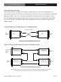
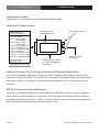
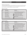
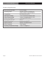
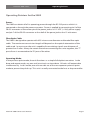
Communications Specialties’ Fiberlink® 5002
User’s Manual
Fiberlink®
5002 Series
RS-232 Digital Data
Transmission System
World Headquarters
55 Cabot Court
Hauppauge, New York 11788 USA
Tel: (631) 273-0404
Fax: (631) 273-1638
[email protected]
commspecial.com
Fiberlink® 5002 Series
Contents
Contents
General Information . . . . . . . . . . . . . . . . . . . . . . . . . . . . . . . . . . . . . . . . . . . . . . . . . . . . . . . 3
Installation Guide. . . . . . . . . . . . . . . . . . . . . . . . . . . . . . . . . . . . . . . . . . . . . . . . . . . . . . . . . . 4
Interface Connections. . . . . . . . . . . . . . . . . . . . . . . . . . . . . . . . . . . . . . . . . . . . . . . . . . . . . . 5
5002 Set to DTE. . . . . . . . . . . . . . . . . . . . . . . . . . . . . . . . . . . . . . . . . . . . . . . . . . . . . . . 5
5002 Set to DCE. . . . . . . . . . . . . . . . . . . . . . . . . . . . . . . . . . . . . . . . . . . . . . . . . . . . . . . 5
Technical Specifications. . . . . . . . . . . . . . . . . . . . . . . . . . . . . . . . . . . . . . . . . . . . . . . . . . . . 6
Operating Pointers. . . . . . . . . . . . . . . . . . . . . . . . . . . . . . . . . . . . . . . . . . . . . . . . . . . . . . . . . 7
Troubleshooting. . . . . . . . . . . . . . . . . . . . . . . . . . . . . . . . . . . . . . . . . . . . . . . . . . . . . . . . . . . 8
Maintenance and Repairs . . . . . . . . . . . . . . . . . . . . . . . . . . . . . . . . . . . . . . . . . . . . . . . . . . 9
Warranty . . . . . . . . . . . . . . . . . . . . . . . . . . . . . . . . . . . . . . . . . . . . . . . . . . . . . . . . . . . . . . . . 10
Page 2
Fiberlink® 5002 Series User’s Manual
General Information
Fiberlink® 5002 Series
General Information
The Fiberlink 5002 is a solid state “optical modem” that transmits RS-232 type data. It is
designed to operate, error free, over distances of more than 2 miles via standard multimode
fiber optic cable. The unit is ideal for extending the normal transmission range of most
RS-232 compatible equipment and accessories and may be user-configured to either the
DCE or DTE mode. The 5002 can be used to implement a point-to-point or a drop-andrepeat system.
Typical Point-to-Point System Configuration
Fiber Optic Cable
To
RS-232
Port
5002
T
T
P
P
R
R
5002
To
RS-232
Port
Operating Power May Be Applied Through The
"P" Port or Through The DB-25 Connector Pins
Typical Drop-and-Repeat System Configuration
To System
Host
RS-232
Port
To
RS-232
Port
T
5002 Set to
Point-to-Point P
R
R
T
T
5002 Set to
P
Drop-and-Rpt
R
P
5002 Set to
Drop-and-Rpt
To
RS-232
Port
5002 Set to
Drop-and-Rpt
To
RS-232
Port
R
Fiber Optic Cable
P
T
Operating Power May Be Applied Through The
"P" Port or Through The DB-25 Connector Pins
Note that the 5002 unit connected to the system Host does not repeat optically received data.
All other units re-transmit both optically received and locally generated data.
Fiberlink® 5002 Series User’s Manual
Page 3
Installation Guide
Fiberlink® 5002 Series
Installation Guide
Following are installation instructions for the Fiberlink 5002:
Individual Transceivers:
DB-25 Signal/
Power Connector
Access port for
DCE/DTE Switch
Pin 1 = Case
Pin 2= Xmit (DTE)
Rec (DCE)
Pin 3= Rec (DTE)
Xmit (DCE)
Pin 4= Jumped to 5
Pin 5= Jumped to 4
Pin 6= Jumped to 8/20
Pin 7= Common
Pin 8= Jumped to 6/20
Pin 9= +12 +10% VDC
Pin 20= Jumped to 6/8
No Connection to
all other pins
See table on next Page
Optical Connectors
External Power
Connector
Install Internal Jumper
for "Drop and Repeat"
Operation
Internal Jumper Pin Setting for Drop and Repeat Operation
For “Drop and Repeat” operation, the case must be snapped open and the internal “D/R”
jumper installed. When this is done, the unit will accept, repeat and output any data within
the loop in which it is installed. For point-to-point operation, the “D/R” jumper must be
removed.
DB-25 Connector Considerations
The 5002 is provided with an industry standard male DB-25 connector. For those applications where a female connector is required, Communications Specialties offers a male-tofemale converter (part number 113024). This device plugs directly into the existing connector and extends the overall length of the unit by ¾ inch.
Page 4
Fiberlink® 5002 Series User’s Manual
Fiberlink® 5002 Series
Interface Connections
Interface Connections
The following tabulation indicates what to look for if the system does not operate properly.
It assumes that correct operating power (12 VDC) has been applied to either pin 9 of the
DB-25 connector or to the coaxial power connector (not both).
5002 set to DTE
Pin
Description
Function
1
Chassis Ground
Chassis Ground
2
Transmit Data
(input) Data to be transmitted on fiber
3
Receive Data
(output) Data received from fiber
4
Request to Send
Connected to pin 5 internally
5
Clear to Send
Connected to pin 4 internally
6
Data Set Ready
Connected to pins 8/20 internally
7
Signal Ground
Signal Ground
8
Data Carrier Detect
Connected to pins 6/20 internally
20
Data Terminal Ready
Connected to pins 6/8 internally
5002 set to DCE
Pin
Description
Function
1
Chassis Ground
Chassis Ground
2
Receive Data
(input) Data received from fiber
3
Transmit Data
(output) Data to be transmitted on fiber
4
Request to Send
(input) Connected to pin 5 internally
5
Clear to Send
(output) Connected to pin 4 internally
6
Data Set Ready
Connected to pins 8/20 internally
7
Signal Ground
Signal Ground
8
Data Carrier Detect
Connected to pins 6/20 internally
20
Data Terminal Ready
Connected to pins 6/8 internally
Fiberlink® 5002 Series User’s Manual
Page 5
Fiberlink® 5002 Series
Technical Specifications
Technical Specification
Data Transmission Rate
Operating Mode
Compatibility
Input Signal Voltage
Output signal Voltage
Optical Loss Budget
Operating Wavelength
Optical Connectors
Signal Connector
Power Connector
Operating Temperature Range
Page 6
DC to 120 Kb/s
Simplex, Duplex, Asynchronous
Point-to-Point, Drop and Repeat
RS-232D, DCE or DTE
+ 5 to +30 volts per EIA RS-232D
+ 5 to +10 volts per EIA RS-232D
15 dB typical 62.5u Fiber
850 nm
Industry standard ST
Industry standard DB-25P
2-Pin Coaxial
-35 to +75 degrees, C
Fiberlink® 5002 Series User’s Manual
Fiberlink® 5002 Series
Operating Pointers
Operating Pointers for the 5002
Power:
The 5002 can obtain all of its operating power through the RS-232 port to which it is
connected or through the power connector. Power is applied by connecting pin 9 of the
DB-25 connector or the center pin of the power jack to a +12 VDC (+ 10%) power supply
and pin 7 of the DB-25 connector or the shell of the power jack to the 12 volt return.
Fiber Optic Cable:
The 5002 is designed to operate with 62.5 micron core diameter multimode fiber optic
cable. The maximum transmission length will depend on the optical attenuation of the
cable used. In most cases the unit is capable of transmitting signals over distances of
greater than 2 miles. Always be certain that when connecting two units together, the “T”
port of one is connected to the “R” port of the other.
Operating Mode:
In the point-to-point mode, the unit functions as a simple full duplex transceiver. In the
drop-and-repeat mode, any one unit (at a time) can input data. All units will output data
simultaneously. In this mode, one unit must be set to the non-repeat or point-to-point
mode to prevent loop lock-up. This unit is usually connected to the host or loop controller.
Fiberlink® 5002 Series User’s Manual
Page 7
Fiberlink® 5002 Series
Troubleshooting
Troubleshooting
Remember to check attenuation of the fiber optic cable. The system will only operate
properly if these specifications fall within the range of the system’s loss budget.
Multimode fiber optic cable contains an optical fiber with a light carrying “core” that is
only .0025 inches (62.5 microns) in diameter. Single mode fiber optic cable has an even
smaller “core,” only .00032 to .0004 inches (8-10 microns). This is smaller than a human hair!
Therefore, any minute particles of dirt or dust can easily block the fiber from accepting or
radiating light. To prevent this from happening, always use the provided dust caps when
ever optical connectors are exposed to air. It is also a good idea to gently clean the tip of an
optical connector with a lint-free cloth moistened with alcohol whenever dust is suspected.
An optical power meter, such as the Fiberlink® 6615, a visible light source, such as the
Fiberlink® 6610, and a Three Wavelength Light Source, such as the Fiberlink® 6620, can
greatly assist and expedite troubleshooting of fiber optic transmission systems and are
recommended tools all installers should have available.
Finally, although multimode and single mode devices may look the same, they will not
operate properly together. Using the wrong device or fiber can easily add more attenuation
than specified, resulting in poor overall performance. It should be noted that some of our
fiber optic products support both single mode and multimode fiber in the same unit.
If, after reviewing the above possibilities, the system is still not operating, please contact
the Customer Service Department for further assistance. If you suspect your problem is
caused by the optics or the fiber optic cable, and you have an optical power meter, please
take the appropriate measurements prior to contacting support.
Page 8
Fiberlink® 5002 Series User’s Manual
Fiberlink® 5002 Series
Maintenance and Repairs
Maintenance and Repairs
The Fiberlink® 5002 Series has been manufactured using the latest semiconductor devices
and techniques that electronic technology has to offer. They have been designed for long,
reliable and trouble-free service and are not normally field repairable.
Should difficulty be encountered, Communications Specialties maintains a complete
service facility to render accurate, timely and reliable service of all products.
The only maintenance that can be provided by the user is to ascertain that optical
connectors are free of dust or dirt that could interfere with light transmission and that
electrical connections are secure and accurate. Please see the Troubleshooting section of
this manual for additional information.
An optical power meter, such as the Fiberlink® 6615, a visible light source, such as the
Fiberlink® 6610, and a Three Wavelength Light Source, such as the Fiberlink® 6620, can
greatly assist and expedite troubleshooting of fiber optic transmission systems and are
recommended tools all installers should have available.
All other questions or comments should be directed to our Customer Service Department.
It should be noted that many “problems” can easily be solved by a simple telephone call.
If you suspect your problem is caused by the optics or the fiber optic cable, and you have
an optical power meter, please take the appropriate measurements prior to contacting
support.
Fiberlink® 5002 Series User’s Manual
Page 9
Fiberlink® 5002 Series
Warranty
Communications Specialties, Inc. (CSI) warrants that, for a period of three years after
purchase by the Buyer, this product will be free from defects in material and workmanship
under normal use and service. A Return Material Authorization (RMA) number must be
obtained from CSI before any equipment is returned by the Buyer. All materials must be
shipped to CSI at the expense and risk of the Buyer.
CSI’s obligation under this warranty will be limited, at its option, to either the repair or
replacement of defective units, including free materials and labor. In no event shall CSI be
responsible for any incidental or consequential damages or loss of profits or goodwill.
CSI shall not be obligated to replace or repair equipment that has been damaged by fire,
war, acts of God, or similar causes, or equipment that has been serviced by unauthorized
personnel, altered, improperly installed, or abused.
RMA numbers and repairs can be obtained from:
Communications Specialties, Inc.
55 Cabot Court
Hauppauge, NY 11788 USA
Tel: (631) 273-0404
Fax: (631) 273-1638
RMA numbers can also be obtained from our web site: commspecial.com
Please have your serial number available.
Page 10
Fiberlink® 5002 Series User’s Manual
Fiberlink® 5002 Series
Fiberlink® 5002 Series User’s Manual
Page 11
Communications Specialties’ Fiberlink® 5002
User’s Manual
Fiberlink®
5002 Series
RS-232 Digital Data
Transmission System
World Headquarters
55 Cabot Court
Hauppauge, New York 11788 USA
Tel: (631) 273-0404
Fax: (631) 273-1638
[email protected]
commspecial.com
©2012 Communications Specialties, Inc.
All Rights Reserved.
Fiberlink and the starburst logo are
registered trademarks of
Communications Specialties, Inc.
CSI and the triangle designs are trademarks
of Communications Specialties, Inc.
P/N 102181 Rev. F