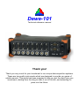
1
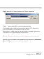
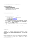
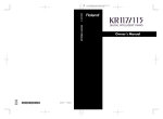
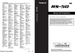
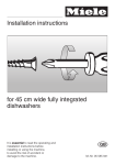
Dewe-101
Technical reference manual
Thank you!
Thank you very much for your investment in our unique data acquisition systems.
These are top-quality instruments which are designed to provide you years of
reliable service. This guide has been prepared to help you get the most from your
investment, starting from the day you take it out of the box, and extending for
years into the future.
DEWE-101
1 Table of contents
1 Table of contents............................................................................... 2
2 Safety Instructions............................................................................. 3
Restriction of Hazardous Substances .................................................. 6
3 Main system ...................................................................................... 9
3.1
Front side connectors ......................................................... 9
3.2
Back side connectors ........................................................ 10
3.3
Connector description ....................................................... 11
3.3.1 Power supply input ....................................................... 11
3.3.2 GPS display connector ................................................. 12
3.3.3 EPAD connector ........................................................... 12
3.3.4 SYNC connector ........................................................... 13
3.3.5 USB interface connectors (Universal serial bus) .......... 13
3.3.6 Ethernet LAN connector ............................................... 13
3.3.7 Power supply for accessories ....................................... 14
3.3.8 VGA connector ............................................................. 14
3.3.9 Analog input connector ................................................. 15
3.3.10 CAN1 / CAN2 input connector ...................................... 15
3.3.11 Counter / Digital input ................................................... 16
3.3.12 Ground connector ......................................................... 16
3.3.13 DEWE 101 power status LED ...................................... 16
3.4
Typical sensor connection ................................................ 17
3.5
Bridge sensor connection ................................................. 19
4 Specifications .................................................................................. 21
5 Using DEWE 101 in Dewesoft ........................................................ 31
5.1
Hardware setup ................................................................. 31
5.2
Using analog/counter/digital/CAN inputs .......................... 34
6 Firmware upgrade ........................................................................... 36
Page 2
Dewe101 Technical reference manual
2 Safety Instructions
The information contained in this document is subject to change without notice.
DEWESOFT d.o.o.. (DEWESOFT) shall not be liable for any errors contained in
this document. DEWESOFT MAKES NO WARRANTIES OF ANY KIND WITH
REGARD TO THIS DOCUMENT, WHETHER EXPRESS OR IMPLIED.
DEWESOFT SPECIFICALLY DISCLAIMS THE IMPLIED WARRANTIES OF
MERCHANTABILITY AND FITNESS FOR A PARTICULAR PURPOSE.
DEWESOFT shall not be liable for any direct, indirect, special, incidental, or
consequential damages, whether based on contract, tort, or any other legal
theory, in connection with the furnishing of this document or the use of the
information in this document.
Warranty Information:
A copy of the specific warranty terms applicable to your DEWESOFT product and
replacement parts can be obtained from your local sales and service office.
Support
Please contact:
DEWESOFT d.o.o.
Gabrsko 11a
1420 Trbovlje
SLOVENIA
Tel.: +386 356 25 300
Fax: +386 356 25 301
Web: http://www.dewesoft.org
The telephone hotline is available
Monday to Friday between
08:00 and 15:00 CET (GMT +1:00)
Page 3
Printing version 1.0 •NOV25, 2009
DEWE-101
Restricted Rights Legend:
Use Slovenian law for duplication or disclosure.
DEWESOFT d.o.o.
Gabrsko 11a
1420 Trbovlje
Slovenia
Printing History:
Version 1.0.0
Released NOV25 , 2009
Copyright © 2009 DEWESOFT d.o.o.
This document contains information which is protected by copyright. All rights
are reserved. Reproduction, adaptation, or translation without prior written
permission is prohibited, except as allowed under the copyright laws.
All trademarks and registered trademarks are acknowledged to be the property of
their owners.
Page 4
Dewe101 Technical reference manual
Safety symbols in the manual:
WARNING
Calls attention to a procedure, practice, or condition that could
cause body injury or death.
CAUTION Calls attention to a procedure, practice, or condition that could
possibly cause damage to equipment or permanent loss of data.
WARNINGS
The following general safety precautions must be observed during all
phases of operation, service, and repair of this product. Failure to comply
with these precautions or with specific warnings elsewhere in this manual
violates safety standards of design, manufacture, and intended use of the
product. DEWESOFT d.o.o. assumes no liability for the customer’s failure
to comply with these requirements.
All accessories shown in this document are available as option
and will not be shipped as standard parts.
Page 5
Printing version 1.0 •NOV25, 2009
DEWE-101
Environmental Considerations
Information about the environmental impact of the product.
Product End-of-Life Handling
Observe the following guidelines when recycling a DEWESOFT system:
System and Components Recycling
Production of these components required the extraction and use of natural
resources. The substances contained in the system could be harmful to your
health and to the environment if the system is improperly handled at it's end of
life! Please recycle this product in an appropriate way to avoid an unnecessary
pollution of the environment and to keep natural resources.
This symbol indicates that this system complies with the European
Union’s requirements according to Directive 2002/96/EC on waste
electrical and electronic equipment (WEEE). Please find further
information about recycling on the DEWESOFT web site
www.dewesoft.org
Restriction of Hazardous Substances
This product has been classified as Monitoring and Control equipment, and is
outside the scope of the 2002/95/EC RoHS Directive. However we take care
about our environment and the product is lead free.
Page 6
Dewe101 Technical reference manual
Safety instructions for all DEWESOFT systems
•
•
•
•
•
•
•
•
•
The DEWESOFT data acquisition systems may only be installed by experts.
Read your manual before operating the system.
Observe local laws when using the instrument.
Ground the equipment: For Safety Class 1 equipment (equipment having a
protective earth terminal), a non interruptible safety earth ground must be
provided from the mains power source to the product input wiring terminals
or supplied power cable.
DO NOT operate the product in an explosive atmosphere or in the presence
of flammable gases or fumes.
DO NOT operate damaged equipment: Whenever it is possible that the
safety protection features built into this product have been impaired, either
through physical damage, excessive moisture, or any other reason,
REMOVE POWER and do not use the product until safe operation can be
verified by service-trained personnel. If necessary, return the product to
DEWESOFT sales and service office for service and repair to ensure that
safety features are maintained.
Keep away from live circuits: Operating personnel must not remove
equipment covers or shields. Procedures involving the removal of covers or
shields are for use by service-trained personnel only. Under certain
conditions, dangerous voltages may exist even with the equipment switched
off. To avoid dangerous electrical shock, DO NOT perform procedures
involving cover or shield removal unless you are qualified to do so.
No modifications are allowed at the instrument. The fuse in the power
module has to be replaced by the same type. For continued protection
against fire, replace the line fuse(s) only with fuse(s) of the same voltage
and current rating and type. DO NOT use repaired fuses or short-circuited
fuse holder labels and print on the power module may not be removed.
DO NOT service or adjust alone. Do not attempt internal service or
adjustment unless another person, capable of rendering first aid and
resuscitation, is present.
Page 7
Printing version 1.0 •NOV25, 2009
DEWE-101
•
•
•
•
•
•
•
•
DO NOT substitute parts or modify equipment: Because of the danger of
introducing additional hazards, do not install substitute parts or perform any
unauthorized modification to the product. Return the product to DEWESOFT
sales and service office for service and repair to ensure that safety features
are maintained.
Before opening the instrument (experts only) or exchanging the fuse in the
power module disconnect power!
Don’t touch internal wiring!
Don’t use higher supply voltage than specified!
Use only original plugs and cables for harnessing.
You may not connect higher voltages than rated to any connectors.
The power-cable and -connector serve as Power-Breaker. The cable must
not exceed 10 feet, disconnect function must be possible without tools.
Safety of the operator and the unit depend on following these rules.
Page 8
Dewe101 Technical reference manual
3 Main system
3.1
Front side connectors
1
2
3
4
5
6
7
Connector overview:
1 Analog input
2 Counter / Digital input
3 Can1 / Can2 input
4 AD Card status LED
5 Ground connector
6 DEWE 101 power status LED
7 Power-on button
Page 9
Printing version 1.0 •NOV25, 2009
DEWE-101
3.2
Back side connectors
8
9
10
11
12
Connector overview:
8 Power supply input
9 GPS display connector
10 EPAD connector
11 SYNC connector
12 USB interface connectors
13 Ethernet LAN connector
14 Power supply for accessories
15 VGA connector
16 GPS antenna connector
17 WLAN antenna connector
Page 10
Dewe101 Technical reference manual
13
14
15
16
17
3.3
3.3.1
Connector description
Power supply input
Power supply input
Input:
Input range:
Input frequency:
Max.input current:
1
3
2
6 - 36Vdc
DC
10A
Pin Assignment
1: V+
2: GND
3: Remote on
System will power on when you press Power on button OR apply V+ voltage to
Remote on pin. To power off system, press Power on button.
Mating connector: LEMO FGG.1B.303.CLAD52
Page 11
Printing version 1.0 •NOV25, 2009
DEWE-101
3.3.2
GPS display connector
The GPS display connector offers the possibility to connect VGPS display to
DEWE-101.
Mating connector: LEMO FGJ.1B.304.CLLD52
4
1
2
3
3.3.3
Pin Assignment
1: +5V
2: GND
3: TX
4: RX
EPAD connector
To connect DEWETRON EPAD modules to the system. EPAD connector is
internally connected to COM2 port.
Mating connector: LEMO FGG.1B.304.CLAD52
1
4
3
2
Pin Assignment
1: RS-485 A
2: RS-485 B
3: +12V
4: GND
Page 12
Dewe101 Technical reference manual
3.3.4
SYNC connector
Mating cable connector: LEMO FGG.00.304.CLAD27Z
1
4
3
2
3.3.5
Pin Assignment
1: Clk
2: Trig
3: PPS
4: GND
USB interface connectors (Universal serial bus)
The USB interface connector meets standard USB pin assignment
3.3.6
Ethernet LAN connector
The DEWE-101 system supports 10/100 BaseT Ethernet with standard RJ45
connector.
Page 13
Printing version 1.0 •NOV25, 2009
DEWE-101
3.3.7
Power supply for accessories
To supply your accessories with power supply input voltage. Voltage is available
when DEWE-101 is running.
Mating cable connector: LEMO FGG.1B.302.CLAD52
1
Pin Assignment
1: V+
2: GND
2
3.3.8
VGA connector
The VGA connector offers the possibility to connect a CRT or other standard
VGA displays to the system.
Pin Assignment
1: Red video
2: Green video
3: Blue video
4: 5: Ground
6: Red video ground
7: Green video ground
8: Blue video ground
9: +5V
10: Ground
11: 12: Data line
13: H-Sync
14: V-Sync
15: Clock
Page 14
Dewe101 Technical reference manual
3.3.9
Analog input connector
9-pin D-SUB female connector for analog input:
5
3
4
9
8
2
7
1
6
Pin Assignment
1: EXC+
2: IN+
3: Sense4: AGND
5: +12V
6: Sense+
7: IN8: EXC9: TEDS
3.3.10 CAN1 / CAN2 input connector
9-pin D-SUB male connector for CAN bus:
1
3
2
6
7
4
8
5
9
Pin Assignment
1: +5V
2: CAN_LOW
3: DGND
4: RES
5 :RES
6: DGND
7: CAN_HIGH
8: RES
9: +12V
Page 15
Printing version 1.0 •NOV25, 2009
DEWE-101
3.3.11 Counter / Digital input
Counter input (mating cable connector: LEMO FGG.1B.307.CLAD52)
7
1
6
2
5
3
4
Pin Assignment
1: IN0/A
2: IN1/B
3: IN2/Z
4: RES
5: +5V
6: +12V
7: DGND
3.3.12 Ground connector
For some kind of measurements, it’s necessary to give the system an additional
ground connection
3.3.13 DEWE 101 power status LED
Status LED indicates current system state (look at table below):
LED indicator
OFF
Green blinking at
startup
Green
Description
System powered down
System starting
Normal operation
Red blinking at
startup
System preheating at cold enviroment ( < 0°C)
Red
Heating / Cooling (Depends on enviromental
temperature)
Page 16
Dewe101 Technical reference manual
3.4
Typical sensor connection
For correct measurements, it is highly recommended to ground the DEWE-101
with GND banana plug on the side.
Sensor with differential output powered by the module
Connector
9
2
7
5
4
Sensor
TEDS
TEDS
IN+
+
Current measurement
9
2
Output
IN+12V
-
7
+
5
Power
GND
-
Sensor
Connector
4
TEDS
4...20mA
IN+
IN-
50 Ohm
4...20mA
Output
+12V
GND
SHD
Loop powered measurement
Connector
5
2
7
4
+12V
+4...20mA
Output
-
IN+
IN-
GND
Sensor with common ground
Sensor
Connector
5
2
50 Ohm
7
4
+12V
IN+
Vdd
Output
IN-
GND
GND
Page 17
Printing version 1.0 •NOV25, 2009
DEWE-101
Single ended connection
Connector
5
2
7
4
Sensor
+12V
IN+
+ Floating
- Output
IN-
Power
supply
GND
Potentiometer sensor connection
1 EXC+
Sense+
6
2
IN+
Sense3 EXC8
7 INGND
4
SHD
Important: If sensors or other signal sources with isolated external power supply
are used, ground signals of DEWE-101 and external power supply should be
connected over connector GND wire or over “common GND” input on housing to
prevent common-mode voltage problems.
Page 18
Dewe101 Technical reference manual
3.5
Bridge sensor connection
Full bridge:
6-wire sensor connection
4-wire sensor connection
EXC+
1 Sense+
6
EXC+
1 Sense+
6
2 IN+
2 IN+
Sense3 EXC8
7 INGND
4
Sense3 EXC8
7 INGND
4
SHD
SHD
Half bridge:
3-wire sensor connection
EXC+
1 Sense+
6
2
EXC+
1 Sense+
6
IN+
Sense3
EXC8
7 INGND
4
3-wire sensor connection
2
SHD
IN+
Sense3
EXC8
7 INGND
4
SHD
Note: Bridge completion needs to be done in the connector.
Page 19
Printing version 1.0 •NOV25, 2009
DEWE-101
Quarter bridge:
3-wire sensor connection
1 EXC+
Sense+
6
2 IN+
Sense3
8 EXC7 IN4 GND
Note: Bridge completion needs to be done in the connector.
Page 20
Dewe101 Technical reference manual
SHD
4 Specifications
Analog inputs
Number of channels
Inputs
ADC type
Sampling rate
Input type
Input ranges
Sensor supply
Overvoltage protection
Dynamic range
DC accuracy 10 V range
1 V range
100 mV range
10 mV range
Input impedance
CMRR
Maximum common mode
voltage
Signal to noise
0.1kS/s to 51.2kS/s
51.2ks/s to 102.4kS/s
102.4kS/s to 200kS/s
8
Voltage, bridge (IEPE, temperature
with adapters)
24 bit sigma delta with
anti-aliasing filter (see section ADC)
simultaneous 200kS/sec sampling
rate
Differential
±10V, ±1V, ±100mV, ±10mV
12V, 400mA sensor supply
±5V ±0.1% bridge sensor supply
±70V input protection
107dB@ ±10V range
0,1% of value +1 mV
0,1% of value +0.5 mV
0,1% of value +0.1 mV
0,1% of value +0.1 mV
20MΩ||47pF(differential)
10MΩ||33pF(common mode)
>80dB (see section CMRR)
±13V
105dB
100dB
75dB
Page 21
Printing version 1.0 •NOV25, 2009
DEWE-101
Counter/Digital inputs
Number of channels
Modes
Counter timebase
Counter resolution
Compatibility
Configuration
Input low level
Input high level
Overvoltage protection
CAN bus
Number of ports
Interface type
Special applications
Galvanic isolation
Bus pin fault protection
ESD protection
General specifications
Power supply
Maximum sensor power
consumption
Maximum power
consumption
Physical dimensions
Weight
Operating temperature
Storage temperature
Humidity
8 counters/24 digital input, fully
synchronized with analog
counting, waveform timing, encoder,
tacho, geartooth sensor
50MHz
32-bit
TTL/CMOS
Pull-up with 100kΩ
-0,7V to 0.7V
2V to 5V
±30V input protection
2
CAN 2.0B, up to 1 MBit/sec
OBDII, J1939, CAN output
Not isolated
±36V
8kV
6-36 V DC
6W
50W
24.5 x 14.5 x 7 cm
2 kg
-20 to 60 deg. C
-40 to 85 deg. C
95% RH non condensing @ 60°C
Page 22
Dewe101 Technical reference manual
Analog input configuration:
Block diagram of analog input (all analog inputs are identical):
IN+
ADC
IN-
AGND
AGND
Input
Termination
Overvoltage
Protection
Pre-filter
Differential
Amplifier
A/D
Converter
The high input impedance (10MΩ ground referenced) has no distortion influence
on the measured signal.
ADC:
The DEWE-101 uses 8 delta-sigma A/D converters. If you sample with a data
rate of 102.4 kS/s, the ADC actually samples the input signal with 13.1072 MS/s
(multiply the data rate with 128) and produces 1-bit samples which are applied to
the digital filter. The filter expands the data to 24-bits and rejects signal parts
greater than 51.2 kHz (Nyquist frequency). It also re-samples the data to the
more conventional rate of 102.4 kS/s.
A 1-bit quantizer introduces many quantization errors to the signal. The 1-bit,
13.1072 MS/s from the ADC carry all information to produce 24-bit samples at
102.4 kS/s. The delta-sigma ADC converts from high speed to high resolution by
adding much random noise to the signal. In this way the resulting quantization
noise is restricted to frequencies above 100 kHz. This noise is not correlated with
the useful signal and is rejected by the digital filter.
ADCs can only represent signals of a limited bandwidth. The maximum frequency
you can represent is the half of the sampling rate. This maximum frequency is
also called Nyquist frequency. The bandwidth between 0 Hz and the Nyquist
frequency is called Nyquist bandwidth. Signals exceeding this frequency range
can not be converted correctly by the sampler.
Page 23
Printing version 1.0 •NOV25, 2009
DEWE-101
For example, the sample rate is 1000 S/s, the Nyquist frequency is 500 Hz. If the
input signal is a 375 Hz sine wave, the resulting samples represent a 375 Hz sine
wave. If a 625 Hz sine wave is sampled, the resulting samples represent a 375
Hz sine wave too. This happens because signals exceeds the Nyquist frequency
(500 Hz). The represented frequency of the sine wave is the absolute value of the
difference between the input frequency and the closest integer multiple of the
sampling rate (in this case 1000 Hz).
When the sampler modulates frequencies out of the Nyquist bandwidth back to
the 0 to 500 Hz baseband it is called aliasing. Signals which are not pure sine
wave can have many components (harmonics) above the Nyquist frequency.
These harmonics are erroneously aliased back to the baseband, added to parts
of the accurately sampled signal and produces a distorted data set. To block
frequencies out of the Nyquist bandwidth, a lowpass filter is applied to the signal
before it reaches the sampler.
Each input channel has its two pole anti-alias lowpass filter with a cutoff
frequency of about 250 kHz. The very high cutoff frequency allows an extremely
flat frequency response in the bandwidth of interest and a small phase error. The
analog filter precedes the analog sampler. The analog sampler operates at 256
times the selected sample rate for rates below 51.2 kS/s, 128 times for rates
between 51.2 kS/s and 102.4 kS/s. For rates over 102.4 kS/s the oversampling is
64 times. That means, the ADC operates at 13.1072 MS/s if you select a sample
rate of 102.4 kS/s (128 * 102.4 kS/s).
The 1-bit oversampled data is passed to a digital anti-aliasing filter. This filter has
no phase error and an extremely flat frequency response. It also has an
extremely sharp roll-off near the cutoff frequency (0.38 to 0.494 times the sample
rate) and the rejection above 0.5465 times the sample rate is greater than 92 dB.
The output stage of the digital filter resamples higher frequencies to 24-bit
samples.
The digital filter passes only signal components within the Nyquist bandwidth or
within multiples of the Nyquist bandwidth of 64, 128 or 256 times (depending on
sampling rate). The analog filter rejects most noise near these multiples. The
following diagrams show the frequency response of the input circuitry.
Page 24
Dewe101 Technical reference manual
Sample rate 0.1kS/s to 51.2kS/s:
Sample rate 51.2kS/s to 102.4kS/s:
Page 25
Printing version 1.0 •NOV25, 2009
DEWE-101
Sample rate 102.4kS/s to 200kS/s:
The ADC samples at 64, 128 or 256 times the data rate (depending on the
adjusted sample rate). Frequency components above one half of the
oversampling rate (> 32, 64 or 128) can alias. Most of this frequency range is
rejected by the digital filter. The filter can not reject components that lie close to
integer multiples of the oversampling rate because it can not differentiate these
components from components between 0 Hz and the Nyquist frequency. That
means, if the sample rate is 100 kS/s and a signal component is between 50 kHz
and 12.8 MHz (128 x 100 kHz), this signal will be aliased into the passband
region of the digital filter and is not rejected. The analog filter removes these
components before they get to the digital filter and the sampler.
If aliasing is caused by a clipped or overranged waveform, (exceeding the voltage
range of the ADC) it can’t be rejected with any filter. The ADC assumes the
closest value to the actual value of the signal in its digital range when the signal
is clipping. The result of clipping is also a sudden change in the signal slope and
results in corrupt digital data with high-frequency energy. This energy is spread
over the complete frequency spectrum and is aliased back into the baseband. Do
not allow the signal to exceed the input range to avoid this.
Page 26
Dewe101 Technical reference manual
Idle channel noise (input terminated with 50Ω):
Page 27
Printing version 1.0 •NOV25, 2009
DEWE-101
Spectral noise - 50Ω termination – 8 averages – 16k lines@50kS/s:
Spectral noise - 50Ω termination – 10 averages – 16k lines@100kS/s:
Spectral noise - 50Ω termination – 10 averages – 16k lines@200kS/s:
Page 28
Dewe101 Technical reference manual
CMRR:
All 8 analog channels of the DEWE-101 are fully differential inputs with resistance
of 10MΩ||10pF. The input voltage range is ±10V, ±1V, ±100mV and ±10mV.
Because of the differential input structure, the difference of the input
(Ch x(+) – Ch x(-)) will be shown as the result of the measurement. Although the
input is protected for input voltages to ±70V, the common voltage range of each
input is limited to about ±13V. If the input voltage exceeds this range, the result is
not valid even when the difference input voltage is lower than current input range.
These voltage ranges will be clipped and introduced as large errors that can be
easily identified in frequency spectrum. The figure bellow show the allowable
common-mode input voltages for various input voltages and measurement
ranges.
Example:
Many signal sources (function generators) and power supplies are floating sources. That means that
they are isolated from each other and from AC power line. If we connect a sensor with differential
output and floating power supply to measurement device, then GND of sensor and measurement
device can have different voltage potential. This is what the measurement device see as commonmode voltage. This common-mode voltage can range from few volts to few hundred volts, but in
almost all cases this renders the measurement. To prevent this effect, GND signals of the sensor and
measurement device need to be directly connected. That way we eliminate common-mode voltage.
On DEWE-101 this connection is possible over connector GND wire or over “Common GND”
receptacle on the housing.
Page 29
Printing version 1.0 •NOV25, 2009
DEWE-101
Counter and digital inputs:
The DEWE-101 is suited with synchronous 32-bit advanced counter and digital
inputs. In addition to the basic counter function like simple event counting,
up/down counting and gated event counting also period time, pulse width, twoedge separation, frequency and all encoder measurements are supported. All
counter inputs can also be used as digital inputs. In addition to the basic counter
input selections, ADC Clock can also be used as counter source. The figure
bellow shows the block diagram of the counter and input overvoltage protection.
Page 30
Dewe101 Technical reference manual
5 Using DEWE 101 in Dewesoft
5.1
Hardware setup
To enable analog input and counter in Dewesoft, go to System – Hardware setup
and choose Dewesoft USB device.
Page 31
Printing version 1.0 •NOV25, 2009
DEWE-101
To enable CAN bus, please go to Can section and select Dewesoft USB device
in CAN section. Make sure that the Hardware clock check box is enabled.
Page 32
Dewe101 Technical reference manual
To enable GPS, please go to GPS section.
In systems with 100Hz GPS, select “Javad GPS” in GPS device section and
COM1 in Com port section.
In systems with 1Hz GPS, select “NMEA compatible GPS” in GPS device section,
COM1 in Com port section, and select 38400 in Baud rate section.
Other cards are valid, but this registration comes with each system.
Page 33
Printing version 1.0 •NOV25, 2009
DEWE-101
5.2
Using analog/counter/digital/CAN inputs
The use of analog inputs, CAN inputs and digital interface is the same as with all
other DAQ devices, which are supported in Dewesoft. Please consult Dewesoft
user’s manual for more information.
If MSI adapters are used, they will be automatically recognized in the amplifier
interface.
Page 34
Dewe101 Technical reference manual
When acquiring data and the USB connection is lost, the acquisition will stop. In
this case reconnect the unit and restart the acquisition with reconnect button.
In this case (if the data was being stored, the gap will be filled in with missing
data).
Page 35
Printing version 1.0 •NOV25, 2009
DEWE-101
6 Firmware upgrade
Please download the latest firmware from Dewesoft web site. Then run “USB
Firmware Upgrade Tool” program.
Part 1: Select DEWEsoft USB in the “Device” combo box.
Press “...” button, select BT_xxx_DW101.fwu file and click Open.
Press Upload button and wait until progress bar reaches 100%. Please don’t
interrupt this operation. Upload takes several minutes.
When upload is finished, press OK and new firmware is uploaded on the device.
If this fails for any reason, repeat Part 1 again.
Now go to Part2…
Page 36
Dewe101 Technical reference manual
Part2: Select DW101 Power Controller in the “Device” combo box.
Press “...” button, select DW101_xxx.fwu file and click Open.
Press Upload button and wait until progress bar reaches 100%. Please don’t
interrupt this operation. Upload takes less than a minute.
When upload is finished, press OK and new firmware is uploaded on the device.
If this fails for any reason, repeat Part 2 again until OK.
Warning: The system may become unusable if upgrade process is interrupted.
When the process is finished, close upgrade tool, shut down DW101, disconnect
power for 10s, reconnect power and power up system.
Page 37
Printing version 1.0 •NOV25, 2009