1
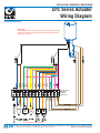
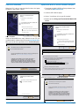
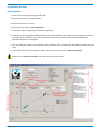
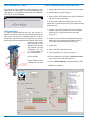
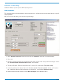
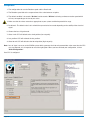
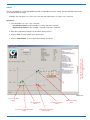
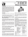
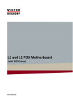
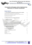
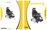
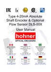
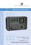
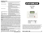
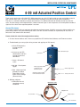
INSTALLATION / OPERATION / MAINTENANCE
CPC
MODEL
4-20 mA Actuated Position Control
Thank you for purchasing a CLA-VAL CPC. With appropriate care, this CPC will provide accurate and reliable control of
your valve for many years. The CPC is built with the latest technology using only very high quality components.
The CPC is a 4-20 mA standalone actuated control which is PC calibrated and able to remotely control any CLA-VAL
valve. The pilot setting can be adjusted with a standard 4-20 mA signal. It also incorporates a 4-20 mA position feedback
signal to cross check if the requested position is reached.
General Disclaimer
In accordance with our policy of continuous development and improvement, CLA-VAL reserves the right to modify or improve these products at any time without prior notice. CLA-VAL assumes no liability or responsibility for any errors or
omissions in the content of this document.
Please review this manual thoroughly before starting
1. Visit our internet address and, if necessary, update the CPC with the latest Software and Firmware versions.
2. Troubleshooting at start up (after wiring actuator and applying 24 VDC power).
CPC
a. View LED diagnostics
located on top of
actuator.
Maintenance port
b. At start-up, the LED
should remain red for 5
seconds than turn to
solid Green
Led indicator
c. Green - OK normal
status.
d. No light - Check power
supply.
e. Red - High torque limit
probably exceeded
Power down and up
again. Excess voltage
(above 32 volts).
Power supply cable
moulded 10 meter
standard execution
Security High Sensor
Input/Output cable moulded
10 meter standard execution
3. Blinking red/green
a. Calibration was not
completed correctly
recalibrate.
Security Low Sensor
Maintenance cable
Adaptable side
PC Connection
Adapter socket
CPC Connection
INSTALLATION / OPERATION / MAINTENANCE
CPC Series Actuator
Wiring Diagram
Wiring Connections
IMPORTANT!
Before applying power, connect cable 3 and 4 to terminal strip as shown.
Also connect: turquoise, pink, and purple wires. Note jumper between
terminals 4, 11 and 13.
Terminal strip not
supplied for
Illustration
purpose only
*
*DO NOT WIRE 24 VDC POWER
CLA-VAL
Page 2
P.O. Box 1325 • Newport Beach, CA 92659-0325 • Phone: 949-722-4800 • Fax: 949-548-5441 • E-mail: [email protected] • Website cla-val.com
© Copyright
Cla-Val 2011 Printed in USA Specifications subject to change without notice.
N-CPC Series Actuator Wiring Diagram
Download Wiring Diagram from website:
(www.cla-val.com)
Electrical Specifications
Electrical Power:
• 24 VDC, 6 / 10 / 15 rpm / sizes
300 mA max. load draw
85 mA stand-by (no load draw)
Other Specifications
Operating Pressure: PN 16 bar standard
Operation Type: Continuous Control
Operating Temperature Range: -10°C to +80°C
Power Protection:
• Max. 32 VDC over voltage
Max. 1000 mA torque load
Reverse polarity & short circuit
80°C stop @ high temperature
Led Display:
Protection: IP68 standard allowing full immersion
(solenoid, junction box, sensor, not
included in IP68)
Interface: Plug & Play / NT / 2000 / XP / Vista
• Green LED
Default Mode
Electrical Connection:
• 2 x Moulded 10 m cables
Troubleshooting:
Refer to user manual for Led diagnostics
(red-green-blinking)
Power Supply:
• 24 VDC +/- 10%, min. 20 mA, normal 60 mA, max. 1 A
Input Command:
Remote Command Failure:
Options available: maintain current position, go to
4 mA position, go to 20 mA position
• 4-20 mA (2 wires)
• 2 x dry contact (manual positioning)
Input 4-20 mA Protection:
• Max. 32 VDC over voltage
Optocoupler isolation @ CMR 100 V
(CMR: common mode rejection)
Insulated (2 wires)
Output feedback:
• 4-20 mA (Output charge ≤ 500 Ω
• 2 x programmable position alarms
Output 4-20 mA Protection:
• Max. 32 VDC over voltage
(The input dry contact and 4-20 mA output have the
same common or earth but are not individually
Isolated
Page 3
Installation Instructions
3. The CPC should be mounted in the vertical position.
4. All installation, adjustment and maintenance should be carried out by a competent electrician.
5. Do not exceed the maximum ratings given in the specifications and printed on the label.
6. The electrical connections should be made as described in the user’s manual.
7. Before any maintenance operation the main power should be turned off.
Do not attempt to open the product as this will invalidate the warranty!
Software / Firmware Updates
For Software updates please visit our web site at www.cla-val.com:
1. Select "Actuators and Controls" to find the latest Software (PC) & Firmware (actuator internal software) updates.
2. Follow instructions to download automatically.
3. All the software is multi-language. Only the installation Software is in French or English.
Firmware Update (Actuator internal Software)
1. Before updating the Firmware, save program to laptop.
2. Connect the USB cable to the USB connection on laptop.
3. Connect the CPC to the USB cable.
4. Select "Read Parameters" to read CPC settings and record output parameters.
5. Select "Firmware update" in "Parameters".
6. Open the corresponding ".hex" file.
7. Select "Read Parameters" to check that the Firmware has been updated.
Page 4
USB Driver Installation
Update USB driver or install in another USB port
When the CPC cable is connected the first time, the laptop
will detect it and request a driver.
Hardware Update Wizard
1. Download the Multi-USB Driver Setup software from
our web site www.cla-val.com.
2. Connect USB cable to laptop.
Welcome to the Hardware Update
Wizard
3. Select: "Install from a list or specific location".
This wizard helps you install software for:
4. Browse to file: C\Program Files\CLA-VAL\Multi-USB
Driver
USB Device
If your hardware came with an installation CD or
floppy disk, insert it now.
Hardware Update Wizard
Welcome to the Hardware Update
Wizard
What do you want the wizard to do?
Install the software automatically (Recommended)
This wizard helps you install software for:
Install from a list or specific location (Advanced)
USB Device
Click Next to continue
< Back
Next >
If your hardware came with an installation CD or
floppy disk, insert it now.
Cancel
Select "Cancel".
Install the "Multi-USB driver setup" software on your PC (you
can download this software from the internet www.cla-val.com).
When you see this message below, select "Continue Anyway".
What do you want the wizard to do?
Install the software automatically (Recommended)
Install from a list or specific location (Advanced)
Hardware Update Wizard
!
Click Next to continue
< Back
The software you are installing for this hardware
Completing the Hardware Update
Wizard
CLA-VAL Muliti-USB Interface
Next >
Cancel
Hardware Update Wizard
This wizard has finished installing the software for
Cla-Val Multi-USB Interface
has not passed Windows Logo Testing to verify it compatbility with
Windows XP. (Tell me why this testing is important)
Please choose your search and installation options.
Search for the best driver in these locations
Continuing your installation of this software may impair or
distabilize the correct operation of your system either
immediately or in the future. Microsoft strongly recommends
that you stop this installation now and contact the hardware
vendor for software that has padded Windows Logo testing.
Use the check boxed below to limit or expand the default search, which includes local paths and
removable media. The best driver found will be installed.
Search removable media (floppy, CD-Rom...)
Include this location in the search
C:\Program Files\CLA-VAL\Muliti-USB Driver Setup
Browse
Click Finish to close the wizard
Donʼt search. I will choose the driver to install
Continue Anyway
STOP Installation
Choose this option to select the device driver from a list. Windows does not guarantee that the
driver you choose will be the best match for your hardware
Hardware Update Wizard
< Back
Completing the Hardware Update
Wizard
Next >
Cancel
Microsoft Validation press "Continue Anyway".
This wizard has finished installing the software for
Cla-Val Multi-USB Interface
Hardware Update Wizard
!
The software you are installing for this hardware
Completing the Hardware Update
Wizard
CLA-VAL Muliti-USB Interface
This wizard has finished installing the software for
Cla-Val Multi-USB Interface
has not passed Windows Logo Testing to verify it compatbility with
Windows XP. (Tell me why this testing is important)
Continuing your installation of this software may impair or
distabilize the correct operation of your system either
immediately or in the future. Microsoft strongly recommends
that you stop this installation now and contact the hardware
vendor for software that has padded Windows Logo testing.
Click Finish to close the wizard
< Back
Finish
Cancel
Click Finish to close the wizard
Installation is complete
Continue Anyway
STOP Installation
Page 5
Hardware Update Wizard
If you are connected to one or more CPC’s or another e-Line
product, click on "View All" then select the CPC you would
like to communicate with from the list (see picture below) then
click once on left mouse button.
The name of product, Firmware version and serial number
are displayed.
Please wait while the wizard installs the software
CLA-VAL Muliti-USB Intervace
e-line list
CPC : (8)..>907060023
Setting a system restore point and backing up old files in case
your system needs to be restored in the future.
< Back
Next >
X
Product
Name
Cancel
Firmware
Version
Serial
Number
View All
Hardware Update Wizard
Cancel
Completing the Hardware Update
Wizard
This wizard has finished installing the software for
Cla-Val Multi-USB Interface
Click Finish to close the wizard
< Back
Finish
Cancel
Configuration Mode
To open e-Drive Software when not connected to the actuator, the e-Line list will be empty. Click "Cancel" to launch. The
software will open so that the various windows can be viewed
to become familiar with the programming.
e-line list
X
View All
Cancel
Page 6
Programming Windows
Display Window
1. Connect CPC to the laptop using the USB cable.
2. Start the e-Drive/CPC CLA-VAL Software.
3. Select the CPC in the e-Line list.
4. Select language and click "Read parameters".
5. On the right side the configuration information is displayed.
6. On the top general information including the date of the latest calibration, the average & total working time since the
first power up, the number of starts, the serial number, the Firmware version and the maximum and minimum
recorded temperature are displayed.
7. Click on continuous reading if you would like see the position of CPC, set point (mA) and feedback position (mA and
units).
8. If you would like to manually change the setting, write your setting and click on "Override Setpoint".
Display pressure values
Activated continuous
reading
Activated override
set point
Page 7
Display Set point and
feedback position
Configuration information
General
information
Improper use of "Override Set Point" may cause damage to your system.
Static Calibration (0% - 100%)
0-100% Calibration without System Pressure
The “Set range” allows calibration in either dynamic or static
mode. When the “Set Range” is clicked, the following message appears. If you would like to proceed with calibration,
click "OK", if not click "Cancel".
e-line list
X
1. Isolate and remove pressure from the valve assembly.
2. Remove plug as shown in figure 1.
3. Open e-Drive / CPC Software then go to "Set Range"
tab and click OK on the menu.
You are going to put the e-Drive / CPC in calibration Mode (Led Blinks Red/Green
OK
4. Select "Static Calibration" Mode and check "CPC
Motor" box is checked and select trim size from the drop
down menu (3).
Cancel
Initial preparation:
It is highly recommended that the valve and actuator assembly is isolated by closing upstream and downstream isolation valves and pressure is removed from valve. If this is
not possible, consult the factory. The objective is to remove
the site plug and visually determine the position of the “orifice
coupling” with respect
to the “stem tube”. They
should be flush with no
gap between the two
assemblies (see Fig.
1). The procedure for
Orifice coupling
this is shown below:
Plug
No gap between
orifice coupling
and stem tube
5. Using the "Increase actuator"/ "Decrease actuator"
Buttons, adjust the position of the “orifice coupling”
until there is no gap (flush) with the stem tube
(See Fig. 1)
6. Select the valve size to be calibrated from the drop
down menu (3) to determine the number of turns
required to achieve full opening of the valve.
7. Select units.
8. Enter 4 mA value and 20 mA value.
9. Turns to low point (1): Enter the number ‘1’.
Orifice coupling
10.Turns to high point (2): Enter the “Number of turns”
value for the valve selected (4) minus ‘1’.
No gap between orifice
coupling and stem tube
11. Select "Write Set Range" to upload settings to CPC.
Calibration is complete
Stem tube
Fig. 1
(3)
(1)
(4)
(2)
Page 8
Calibration - Variable Range
Calibration Mode to a specific process WITH System pressure.
Initial preparation:
This calibration mode is for field installations where water pressure is available and you want to control flow over a specific
range of positions.
Now you are in the calibration, please enter the required settings.
1. Select "Dynamic Calibration" mode and ensure that the "CPC Motor" check box is checked (Enabled).
2. Select units.
3. Enter the required setting Value at 4 mA point and Value at 20 mA point. Look at the position on the display and use
the "Increase actuator / Decrease actuator" button, until it reaches.
4. The low position point. When the low position point is reached click on the button "Low point setting".
5. Look at the position on the display and use the "Increase actuator / Decrease actuator" button, until it reaches
the high position.When the high position point is reached click on the button "High point setting".
6. When all values have been entered, click on "Write Set Range". Your calibration is done.
Page 9
Configuration
1. The configuration tab sets the Rotation speed and the Dead band.
2. The Rotation speed affects the response time of the valve between set-points.
3. The default condition is 0 seconds "On-time" and 0 seconds "Off-time" achieving continuous rotation speed which
will vary corresponding to the size of your valve.
4. Make sure that the values entered are appropriate to your system to minimize potential for surge.
5. Dead band - The default value is 0.1 mA which may need to be increased depending on the stability of the electrical
signal.
6. Choose the loss of signal mode.
7. Go to 4 mA: CPC will default to the 4 mA position (low set point).
8. Last position: CPC will maintain the last position.
9. Go to 20 mA: CPC will default to the 20 mA position (high set point).
Note: Loss of signal can occur on the SCADA system which generates the 4-20 mA command but at the same time the CPC
can stay powered, so it is important to select the right option. When you have finished your configuration, click on
"Write Configuration".
Your CPC is configured.
Page 10
Alarms
The CPC incorporates a LOW and HIGH Alarm with an adjustable hysteresis setting. The low and High alarm levels
are activated within the range:
Example: 10% low alarm = 4 + (10% x 16) = 5.6 mA. 90% High alarm = 4 + (90% x 16) = 18.4 mA.
Hysteresis:
1. The calculation is: 4 + (2% x 16) = 0.32 mA.
Low alarm hysteresis in this example = 5.6 mA + 0.32 mA = 5.92 mA.
High alarm hysteresis in this example = 18.4 mA - 0.32 mA = 18.08 mA.
2. Enter the requested percentage, for the alarms and hysteresis.
3. Click on "Test" to close or open your contact relay.
Adjustment of alarms high, low
level and hysteresis alarm level
2%
4. Click on "Write Alarms" (1) once your alarm settings are correct.
(1)
LIN040UE-07
"Low Level" alarm
range
"Low Level" alarm
value
"Low Level" hysteresis alarm
value
"High Level" alarm
range
"High Level" alarm
value
"High Level" hysteresis
alarm range
Page 11
Your complete source for top quality
automatic control valves
and related products
GLOBAL HEADQUARTERS
P.O. Box 1325
Newport Beach, CA 92659-0325
Phone: (949) 722-4800
1-800-942-6326
Fax: (949) 548-5441
E-mail: [email protected]
WESTERN REGION
11626 Sterling Avenue, Suite F
Riverside, CA 92503
Phone: (951) 687-9145
1-800-247-9090
Fax: (951) 687-9954
E-mail: [email protected]
CLA-VAL CANADA
4687 Christie Drive
Beamsville, Ontario
Canada L0R 1B4
Phone: (905) 563-4963
Fax: (905) 563-4040
E-mail: [email protected]
SOUTHERN REGION
11500 NW Freeway Suite #200Q
Houston, TX 77092
Phone: (713) 681-9559
1-800-336-7171
Fax: (713) 681-9779
E-mail: [email protected]
CLA-VAL EUROPE
Chemin dés Mesanges 1
CH-1032 Romanel/Lausanne
Switzerland
Phone: 41-21-643-15-55
Fax: 41-21-643-15-50
E-mail: [email protected]
NORTHERN REGION
P.O. Box 863
Elgin, IL 60121
280 Willard Avenue
Elgin, IL 60120
Phone: (847) 697-1413
1-800-238-7070
Fax: (847) 697-5549
E-mail: [email protected]
CLA-VAL UK
Dainton House, Goods Station Road
GB - Tunbridge Wells
Kent TN1 2 DH
England
Phone: 44-1892-514-400
Fax: 44-1892-543-423
E-mail: [email protected]
CLA-VAL FRANCE
Porte du Grand Lyon 1
ZI de Champ du Périer
France - 01700 Neyon
Phone: 33-4-72-25-92-93
Fax: 33-4-72-25-04-17
E-mail: [email protected]
EASTERN REGION
6911 Richmond Highway, Suite 444
Alexandria, VA 22306
Phone: (703) 721-1923
1-800-451-3030
Fax: (703) 721-1927
E-mail: [email protected]
CLA-VAL PACIFIC REGION
306 Port Hills Road, (Level Two)
Woolston, Christchurch, 8022
New Zealand
Phone: (64) 39644860
Fax: (64) 39644876
E-mail: [email protected]
www.cla-val.com • 800.942.6326
N-CPC (R-3/2011)