1
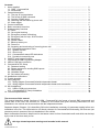
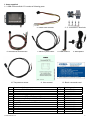
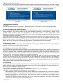
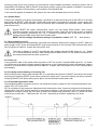
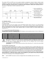
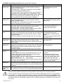
CommandCall® CC1
GSM communication module
User & Installations Manual
Order Number
206300322700
PC Setup 1.4
Controll SW 1.14
Contents
1. Items supplied
...........................................................................
1.1. GSM CommandCall
...........................................................................
1.2. Accessories
...........................................................................
2. General description
...........................................................................
2.1. The way of communication
...........................................................................
2.2. The format of SMS command
...........................................................................
2.3. Content of SMS report
...........................................................................
2.4. Switching ON the heater by phone call
...........................................................................
2.5. Alarm trigger
...........................................................................
3. Control commands
...........................................................................
4. Basic commands overview
...........................................................................
5. Supplementary functions
...........................................................................
5.1. Panic
...........................................................................
5.2. Car engine blocking
...........................................................................
5.3. Emergency release of blocking
...........................................................................
5.4. Emergency ask for help - SOS function
...........................................................................
5.5. Monitoring
...........................................................................
5.6. System Reset
...........................................................................
5.7. Back up battery cut
...........................................................................
5.8. Power cut
...........................................................................
5.9. Accepting and terminating of incoming phone call
...........................................................
5.10. Exceeded temperature limits
...........................................................................
5.11. Speaker volume
...........................................................................
5.12. Short circuit
...........................................................................
5.13. CommandCall status LED indications
...........................................................................
5.14. Periodical connectivity test
...........................................................................
6. ON/OFF push button functions
...........................................................................
7. CommandCall USB Programming Adapter
...........................................................................
8. USB to COM port conversion
...........................................................................
9. CommandCall PC Setup
...........................................................................
9.1. Password setting
...........................................................................
9.2. Phone numbers for sending SMS reports
...........................................................................
9.3. SMS settings
...........................................................................
9.4. Variables range
...........................................................................
9.5. Set values processing
...........................................................................
10. Installations instructions
...........................................................................
11. Trouble shooting
...........................................................................
12. Wiring diagram
...........................................................................
12.1. Wiring diagram CommandCall with independent heater
...................................................
12.2. Wiring diagram CommandCall with independent heater and accessories
....................
13. SW Installations
...........................................................................
13.1. USB to COM port conversion
...........................................................................
13.2. CommandCall PC Setup Installation
...........................................................................
14. Technical specifications
...........................................................................
2
2
3
3
3
3
4
4
4
5
11
11
11
11
11
11
11
12
12
12
12
12
13
13
13
13
14
15
15
16
18
18
18
19
19
20
21
22
22
23
24
24
28
30
The structure of this manual
This manual describes single functions of GSM CommandCall, the format of control SMS commands and
reports sent to the user, unit controls via installed in the vehicle and gives mounting instructions for unit
installation in the vehicle and its connection with the independent heater.
Separate chapter (Chapter 13) is describing SW tools installations necessary for parameter setting before unit
installation in the car. This information is not directly relevant for CommandCall functionality, SW tools are just
necessary tools in process of the unit installation in the vehicle.
Basic commands overview is helpful tool for the heater control in form of standard credit card which can be kept
by the user all the time ready to use.
this sign shows important warnings and remarks in this manual
CommandCall CC1
1
1. Items supplied
1.1. GSM CommandCall CC1 consist of following parts:
1. Control unit
2. Heater wire harness
6. Accessories wire harness
7. ON/OFF push button
10. Temperature sensor
8. GSM antenna
11. User manual
Item Item description
CommandCall CC1- full set
1
Control unit
2
Heater wire harness
3
Connector body Tyco 6P (terminals)
4
Connector body Tyco 6P (receptacles)
5
Terminal receptacle (Junior-Power-Timer)
6
Accessories wire harness
7
ON/OFF push button with LED indication
8
GSM antenna
9
Microphone
10 Temperature sensor
11 User & installation manual
12 Basic commands card
CommandCall CC1
3.- 5. Connectors / terminals
9. Microphone
12. Basic commands card
Qty
1
1
1
1
1
4
1
1
1
1
1
1
1
Ordering code
206300322700
206300329000
206300801101
929505-2
929504-2
927775-3
206300801102
206300328400
206300321100
206300321000
206300324900
N-206300322700-002
N-206300322700-201
2
1.2. Accessories
The CommandCall CC1 functionality may be extended added with following parts:
4/5. Blocking relay
1. USB Programming Adapter
Item
1
2
3
4
5
6
2. GSM window antenna
Item description
CommandCall USB Programming Adapter
GSM window antenna
Speaker
Blocking relay 12V / 30A
Blocking relay 24V / 20A
Relay wire harness
3. Speaker
Qty
1
1
1
1
1
1
6.Relay wire harness
Ordering code
206300001700
206300321101
206300320002
2-1393302-2
5-1393302-1
0-0999017-1
2. General description
GSM communication module CommandCall is used for transfer of control commands and reports between the
user and the vehicle via SMS of GSM network. Unit transfers information gained from built in vehicle alarm,
enables control and monitoring of the status of independent heater in vehicle via SMS commands and reports,
measuring actual in car temperature, monitoring of in car activities via phone call with the vehicle (for example
when car alarm is triggered) and to switch ON the heater by phone call.
Integrated part of the CommandCall is built in GSM module (phone) supporting SIM 3V cards of any GSM
mobile operator at 900 &1800 MHz. In the system may be used any post-paid or prepaid SIM card. In the case
of using prepaid SIM card it is important to watch SIM card validity (expiration) and keeping necessary credit
available on the card to be sure the system is ready to send SMS report to the user when needed. Some mobile
operators offer the feature of automatic maintenance of minimal credit.
GSM communication module CommandCall CC1 can be used in any type of vehicle due to its voltage auto
sensing feature (auto sensing 12 / 24V).
CommandCall is not an ALARM, it is GSM communication module used for transfer of commands
and reports for independent heater control in the vehicle.
CommandCall can be connected to built in car alarm and then alarm signals can be taken in
consideration and the user can be informed accordingly.
2.1. The way of communication
The user communicates with in the car installed unit via sending and receiving SMS or by making phone call.
The format of sent commands is described in the table „Control commands“ (Chapter 3). Format of the
commands is fixed, the format (text) of SMS reports which CommandCall sends to the user may be set during
the unit installation. All parameters except PIN code of SIM card may be changed / set during standard
operation by specific SMS command.
2.2. The format of SMS command
The format of SMS commands has fixed syntax: „password“ „command code“ „command parameter“, while
„password“
consist of 4 digits
„command code“
consist of one to three digits
„command parameter“ is specific for each command and can contain phone number, time information,
requested temperature value, ...
CommandCall CC1
3
For commands code with leading zero(s) may be used in „short“ version, e.g. with leading
zero(s) omitted. For example the command „003“ can be used in short version as „3“.
In between the password, command code and command parameter no separator is used (comma,
space, ...).
User password is factory set to the value 1234. By setting checkbox „Password disable“ in
CommandCall PC Setup it is possible to disable using user password in the system and then all SMS
commands starts directly with the command code (in such case the password is not used at all).
User password is possible to change any time by using SMS command „284“ or in PC Setup.
Execution and confirmation of individual command can be delayed depending on actual
traffic in used GSM network.
2.3. Content of SMS report
The content of SMS reports (text of SMS reports) sent to the user is factory preset but it is possible to change it
during system installation by using CommandCall PC Setup. Reports texts can be in local language. SMS
reports can contain the characters of English alphabet (does not contain local characters).
Format of reports sent by the system to the user which contain beside the text also parameter value is not
possible to modify by the user („fix“ type report).
SMS reports sent by CommandCall to the user can be separated into 2 categories:
• reports sent by the system to the user based on specific event:
CommandCall sends the report to the user after processing specific event (pressing , switching the heater
ON or OFF by external clock, the signal received from the built in alarm, periodical test timeout, ...).
Up to 4 phone numbers can be stored in CommandCall memory used for automated sending SMS reports.
The first phone number for sending SMS reports is used for sending „standard“ reports,
„emergency“ reports are sent always to all stored phone numbers (as „emergency“ reports are considered:
alarm trigger report, ignition ON (after alarm trigger), Power cut and S.O.S.).
• answer to user request:
CommandCall sends report to the user after receipt of SMS command or user request (switch ON or OFF
the heater, setting system parameter, request on actual heater status and/or in car temperature, ...).
CommandCall answers to the user request by sending SMS report to the phone number from
which original request / command was sent to CommandCall.
Sending out of each respective SMS report is based on condition that relevant checkbox is activated
during system installation by using CommandCall PC Setup. The change of checkbox activation
settings is possible any time by using SMS command „290“.
It is important to activate only those checkboxes which reports are necessary for proper user
information and correct operation of the unit (keep in mind that sending SMS reports is charged
according to used prepaid or post-paid program of respective GSM network operator).
2.4. Switching ON the heater by phone call
When checkboxes No.19 - “Phone activate” and No.20 - “Heater start by phone call” are both activated
incoming phone call is indicated by flashing LED of ON/OFF push button and by ringing tone in the speaker (if
connected) and the phone call will be handled as follows:
a. incoming phone call can be “Accepted” or “Rejected” within 10 seconds by pressing ON/OFF push button
b. if incoming phone call is not “Accepted” or “Rejected” within 10 seconds by pressing ON/OFF push button
system evaluates such phone call as request to switch ON the heater - the heater will be switched ON and
phone call terminated. If checkbox No.4 is activated SMS report No.4 - “Heater ON by phone” is sent to
calling phone.
2.5. Alarm trigger
After car alarm defence area was triggered the system starts (after 3 seconds delay) the car horn (interrupted
sound) and CommandCall will dial the first preset phone number. After 15 seconds ringing system will terminate
the phone call and will send SMS No. 14 - “Alarm trigger” to all stored phone numbers (max 4 numbers). User
can press “Call terminate” button on his mobile phone to hang up the phone and to receive short message
immediately.
When vehicle ignition is switched ON (ACC ON) while the alarm is triggered the system will send SMS report
No. 17 - „ACC trigger“ to all stored phone numbers.
If the first phone number stored in CommandCall is blank the system will use next phone number
„Checkbox“ and „SMS report“ listed in following table of control commands are links to relevant
checkboxes and text of SMS report related to specific command or system function.
Checkboxes and SMS report texts are accessible through CommandCall PC Setup.
CommandCall CC1
4
3.Control commands
Checkbox
SMS
report
“Eberspaecher OFF by SMS, ±
ttt.t C”
1
1
“Eberspaecher OFF by button,
± ttt.t C”
2
2
“Eberspaecher OFF by clock, ±
ttt.t C”
3
3
“Eberspaecher ON by phone,
MMM min., ± ttt.t C”
4
4
“Eberspaecher ON by button,
MMM min., ± ttt.t C”
5
5
“Eberspaecher ON by clock, ±
ttt.t C”
6
6
„Eberspaecher OFF, ± ttt.t C”
„Eberspaecher ON by phone,
MMM min., ± ttt.t C”
„Eberspaecher ON by button,
MMM min., ± ttt.t C”
„Eberspaecher ON by clock, ±
ttt.t C”
-
33
4
-
5
-
6
Command
Command
Description
Text of SMS report
code
000
Switch OFF the heater by SMS command
If the heater was switched ON by SMS command or by push
button prior receipt of SMS command in form xxxx000 (xxxx
is user password) the system will switch OFF the heater and
will send respective SMS report. Temperature is shown only
if checkbox No. 32 is activated. If the heater was switched
ON by external clock this command will have no effect.
If the heater was switched ON by SMS command or by push
button the system will switch OFF the heater and will send
respective SMS report. Temperature is shown only if
checkbox No. 32 is activated. If the heater was switched ON
by external clock this command will have no effect.
If the heater was switched ON by external clock it can be
switched OFF only by external clock. Temperature is shown
only if checkbox No. 32 is activated.
Receiving SMS command in form xxxx001 (xxxx is user
password) will switch ON the heater for preset time and
when preset time expires the heater will be switched OFF.
After starting the heater system will send SMS No. 4.
Remaining time and temperature is shown only if respective
checkboxes No. 31 and 32 are activated.
Pressing ON/OFF push button will switch ON the heater for
preset time and when preset time expires the heater will be
switched OFF. After starting the heater SMS No. 5 is sent.
Remaining time and temperature is shown only if respective
checkboxes No. 31 and 32 are activated.
Heater will be switched ON by external clock and will stay
ON depending on external clock setting.
After starting the heater system will send SMS No. 6.
Temperature is shown only if checkbox No. 32 is activated.
After receiving SMS command in form xxxx002 (xxxx is
user password) system will respond to the user by sending
respective SMS report depending on current state of the
heater.
Remaining time and temperature is shown only if respective
checkboxes No. 31 and 32 are activated.
-
Switch OFF the heater by ON/OFF push button
-
Switch OFF the heater by heater external clock
001
Switch ON the heater by SMS command for preset time in
range 1 to 120 minutes.
For preset value 999 the heater will be switched ON for
unlimited time. Preset time can be set in PC Setup or by
SMS command 281.
-
Switch ON the heater by ON/OFF push button for preset
time in range 1 to 120 minutes.
For preset value 999 the heater will be switched ON for
unlimited time
-
Switch ON the heater by external clock.
002
request for heater status. Possible states are:
- Heater OFF
- Heater ON by SMS or by phone call
- Heater ON by ON/OFF push button
- Heater ON by external clock
CommandCall CC1
5
Command
Command
code
003
Remaining heating time and actual temperature
004
005
006
007
010
Description
Text of SMS report
If the heater was switched ON by phone (SMS command or “MMM min., ± ttt.t C“
phone call) or by push button prior receipt of SMS command
in form xxxx003 (xxxx is user password) the system will
send SMS containing number of minutes remaining till
switching heater OFF and actual in car temperature.
If the timer preset value = 999 system will send SMS No. 7. “Eberspaecher unlimited ON, ±
ttt.t C””
If the heater was switched ON by external clock the system „Eberspaecher ON by clock, ±
ttt.t C“
will send SMS No. 6.
„Eberspaecher OFF, ± ttt.t C”
If the heater is OFF the system will send SMS No. 33.
In command 003 remaining heating time and temperature
are shown regardless relevant checkboxes setting.
Request for actual in car temperature
After receiving SMS command in form xxxx004 (xxxx is
“± ttt.t C“
user password) system will send SMS containing value of
measured temperature in degrees Celsius. Working range
of temperature sensor is - 40.0 to +125.0 °C.
In command 004 actual in car temperature is shown
regardless checkbox No.32 setting.
Panic
After receiving SMS command in form xxxx005 (xxxx is
„Panic OK“
user password) system will sound horn intermittent for 30
seconds and sends SMS No.8 to the user
Anti car jacking - car engine blocking - if ignition of the
After receiving SMS command in form xxxx006 (xxxx is
„Engine blocking OK“
vehicle is OFF (ACC OFF) when blocking command is
user password) system will start „blocking“ procedure - will
received the system will cut off fuel pump immediately and
cut fuel pump and will send SMS No. 9 to the user.
sounds horn intermittent for 30 seconds. If ignition of the
If the checkbox No. 24 is activated it is possible to make
vehicle is ON (ACC ON) when blocking command is
„monitoring“ call within 10 minutes.
received the system will sound horn intermittent for 30 sec. Monitoring call is automatically accepted without any sound
followed with 30 seconds pause. This cycle can be repeated or LED indication in the car.
maximally 10 times. System waits for switching ignition OFF.
When the ignition is switched OFF system will cut off fuel
pump immediately and sounds horn intermittent for 30 sec.
Emergency release
Receiving SMS command in form xxxx007 (xxxx is user
„Emergency release OK“
password) will release car engine blocking and sends SMS
report No. 10 .
Switch ON the heater for 10 minutes
Receiving SMS command in form xxxx010 (xxxx is user
„Eberspaecher ON, MMM min.,
password) will switch ON the heater and 10 minutes later
± ttt.t C”
will switch it OFF. When switching ON the heater SMS
No.11 is sent. Remaining time and temperature are shown
only if respective checkboxes No. 31 and 32 are activated.
CommandCall CC1
6
Checkbox
SMS
report
-
fix
-
7
-
6
33
-
fix
8
8
9
9
10
10
11
11
Checkbox
SMS
report
„Eberspaecher ON, MMM min.,
± ttt.t C”
11
11
„Eberspaecher ON, MMM min.,
± ttt.t C”
„Eberspaecher ON, MMM min.,
± ttt.t C”
11
11
11
11
„281 - MMM min. - OK“
18
fix
„Monitoring enabled“
12
12
„Password change OK“
18
34
„Password disable OK“
18
36
„Password change OK“
18
34
„285 OK“
18
fix
„286 OK“
18
fix
„287 OK“
18
fix
Command
Command
Description
Text of SMS report
code
011
Switch ON the heater for 11 minutes
Receiving SMS command in form xxxx011 (xxxx is user
password) will switch ON the heater and 11 minutes later
will switch it OFF. When switching ON the heater SMS
No.11 is sent. Remaining time and temperature are shown
only if respective checkboxes No. 31 and 32 are activated.
12-119 Switch ON the heater for 12 to 119 minutes
120
Switch ON the heater for 120 minutes
281
Setting heater timer preset (HTP) value.
282
Monitoring enable
284
User password change
285
Change of phone number 1
286
Change of phone number 2
287
Change of phone number 3
CommandCall CC1
Receiving SMS command in form xxxx120 (xxxx is user
password) will switch ON the heater and 120 minutes later
will switch it OFF. When switching ON the heater SMS
No.11 is sent. Remaining time and temperature are shown
only if respective checkboxes No. 31 and 32 are activated.
Receiving SMS command in form xxxx281MMM (xxxx is
user password) will set heater timer preset to specified
value. MMM is value in range 1 to 120 minutes.
For MMM=999 the heater will be switched ON unlimited
Receiving SMS command in form xxxx282MMM (xxxx is
user password) will enable monitoring of the vehicle for 10
minutes from receiving the command. After calling on built in
phone in CommandCall within 10 minutes the call is
automatically accepted without any indication in the vehicle
(no ringing tone or LED flashing) and user can listen to the
sounds in the vehicle.
Receiving SMS command in form xxxx284MMM (xxxx is
user password) will change the user password from xxxx to
NNNN. Command in form xxxx284 (xxxx is user password)
will disable using of user password.
Command in form 284NNNN will restore using of user
password and will set its new value NNNN.
Receiving SMS command in form xxxx285MMM (xxxx is
user password) will set the first phone number for sending
SMS reports, +NNN is country code, T...T is phone number
Command xxxx285 will erase the first phone number.
Receiving SMS command in form xxxx286MMM (xxxx is
user password) will set the second phone number for
sending SMS reports, +NNN is country code, TT...T is
phone number.
Command xxxx286 will erase the second phone number.
Receiving SMS command in form xxxx287MMM (xxxx is
user password) will set the third phone number for sending
SMS reports, +NNN is country code,TT...T is phone number
Command xxxx287 will erase the third phone number.
7
Checkbox
SMS
report
„288 OK“
18
fix
“290 OK”
18
fix
-
fix
“Invalid command”
13
13
“Alarm trigger”
14
14
“S.O.S.”
15
15
“Power cut”
16
16
“ACC trigger”
17
17
18
-
19
-
Command
Command
Description
Text of SMS report
code
288
Change of phone number 4
Receiving SMS command in form xxxx288MMM (xxxx is
user password) will set the fourth phone number for sending
SMS reports, +NNN is country code, TT...T is phone number
Command xxxx288 will erase the fourth phone number.
Receiving SMS command in form xxxx290NNNN...N (xxxx
is user password) will set all checkboxes as specified by
respective N. Each N can contain „0“ for deactivating and
„1“ for activating of respective checkbox. The number of
respective checkbox is given by position in the sequence.
Receiving SMS command in form xxxx291 (xxxx is user
password) will send SMS containing sequence of 32
characters „0“ or „1“, where each “0” means deactivated
and „1“ activated respective checkbox. The position in the
sequence gives number of the respective checkbox (1 - 32)
Receiving SMS command with wrong user password,
command code or parameter value is rejected and SMS No.
13 is sent to the user.
When systems gets signal from the car alarm it will send
SMS report No. 14 to all stored phone numbers (max. 4
phone numbers for sending SMS reports)
Pressing ON/OFF push button for at least 5 seconds (max.
20 seconds) will send S.O.S. report to all stored phone
numbers (max. 4 phone numbers)
After power cut is detected system sends SMS report to all
stored phone numbers (max. 4 phone numbers)
When systems gets signal from the car alarm and later
ignition is switched ON (ACC ON) system will send SMS
report No. 17 to all stored phone numbers (max. 4 phone
numbers for sending SMS reports)
Activating the checkbox No. 18 will enable sending
confirmation SMS after execution of those commands which
do not have specific checkbox.
Activating the checkbox No. 19 will enable phone calls on
built in phone in CommandCall. Incoming phone call is
indicated by flashing LED of ON/OFF push button and
ringing tone in the speaker (if connected).
Functions “Accept”, “Reject” and “Terminate” the phone call
by ON/OFF push button are activated.
If the checkbox 19 is not activated it is not possible to make
phone call on CommandCall built in phone (such phone call
is not indicated) except 10 minutes of „monitoring enabled“.
290
Checkboxes settings
291
Request on actual setting of checkboxes
-
Invalid command
-
Alarm trigger
-
SOS
-
Power cut
-
ACC ON (ignition)
-
Command execution confirmation
-
Activate built in phone
CommandCall CC1
8
„291 OK NNNN.......NNNNN“
Command
Command
Description
code
-
Switch ON the heater by phone call
Activating the checkbox No. 20 will enable to switch the
heater ON by phone call to CommandCall. Incoming phone
call is indicated by flashing LED of ON/OFF push button and
ringing tone in the speaker (if connected). If incoming phone
call is not “Accepted” or “Rejected” within 10 seconds by the
driver of the vehicle the heater will be switched ON and
phone call terminated.
If the checkbox No. 4 is activated system will send SMS No.
4 to callers phone. Remaining time and temperature is
shown only if respective checkboxes No. 31 and 32 are
activated.
Activating the checkbox No. 21 will enable periodical
connectivity test by sending SMS No. 21 in set time period
indicating system operability.
Activating the checkbox No. 22 will automatically enable
monitoring for 10 minutes after Alarm trigger signal received
Activating the checkbox No. 23 will automatically enable
monitoring for 10 minutes after SOS function activation.
Activating the checkbox No.24 will automatically enable
monitoring for 10 minutes after engine blocking activation.
Receiving SMS command in form xxxx320ttt.t (xxxx is user
password) will set UST to ttt.t value, ttt.t is temperature
value in range -40,0 to +125,0 degrees Celsius.
Receiving SMS command in form xxxx321sss (xxxx is user
password) will set TS to sss value, sss is time value in range
0 to 999 seconds.
Activating the checkbox No. 25 will enable sending SMS
No. 25 in the case actual temperature decreases under UST
and stay bellow UST longer than specified time TS.
Activating the checkbox No. 26 will enable sending SMS
No. 26 in the case actual temperature increases over UST
and stay over UST longer than specified time TS.
Receiving SMS command in form xxxx322ttt.t (xxxx is user
password) will set UST1 to ttt.t value, ttt.t is temperature
value in range -40,0 to +125,0 degrees Celsius.
Receiving SMS command in form xxxx323ttt.t (xxxx is user
password) will set UST2 to ttt.t value, ttt.t is temperature
value in range -40,0 to +125,0 degrees Celsius
.
Receiving SMS command in form xxxx324sss (xxxx is user
password) will set TS1 to sss value, sss is time value in
range 0 to 999 seconds
-
Periodical connectivity test
-
Monitor enable when Alarm triggered
-
Monitor enable when SOS
-
Monitor enable when car engine blocking
320
321
-
322
323
324
Setting UST temperature (User Set Temperature). System
compares actual in car temperature with UST value, when
exceeded system will send respective SMS report to user.
Setting time delay TS, during which must actual temperature
exceed UST value to be recognized as limit level break
(for exclusion of short term temperature change / seal)
The checkbox No. 25 „UST exceeded - temperature
decreasing“
The checkbox No. 26 „UST exceeded - temperature
increasing“
Setting UST1 temperature - upper temperature interval limit.
System compares actual in car temperature with UST1
value, when exceeded system will send respective SMS.
Setting UST2 temperature - lower temperature interval limit.
System compares actual in car temperature with UST2
value, when exceeded system will send respective SMS.
Note: UST1 > UST2
Setting time delay TS, during which must actual temperature
exceed UST1 or UST2 value to be recognized as limit level
break (for exclusion of short term temperature change/seal)
CommandCall CC1
Checkbox
SMS
report
20
-
„Periodical connectivity test OK
21
21
-
22
-
-
23
-
-
24
-
„320 - UST = ± ttt.t C - OK“
18
fix
„321 - TS = sss seconds - OK“
18
fix
“Temp. decreased below UST”
25
25
“Temp. increased over UST”
26
26
„322 - UST1 = ± ttt.t C - OK“
18
fix
„323 - UST2 = ± ttt.t C - OK“
18
fix
„324 - TS1 = sss seconds - OK“
18
fix
Text of SMS report
9
Command
Command
code
-
The checkbox No. 27 „Entering the interval from top“
-
-
-
325
326
327
Description
Checkbox
SMS
report
“Temp. decreased into interval”
27
27
“Temp. increased into interval”
28
28
“Temp. left interval down”
29
29
“Temp. left interval up”
30
30
„325 - PTD = dd days“
18
fix
„326 - PTH = hh hours“
18
fix
„327 - PTM = mm minutes“
18
fix
Text of SMS report
Activating the checkbox No. 27 will enable sending SMS
No. 27 in the case actual temperature decreases under
UST1 and stay bellow UST1 longer than specified time TS1
The checkbox No. 28 „Entering the interval from bottom“
Activating the checkbox No. 28 will enable sending SMS
No. 28 in the case actual temperature increases over UST2
and stay over UST2 longer than specified time TS1.
The checkbox No. 29 „Leaving the interval down“
Activating the checkbox No. 29 will enable sending SMS
No. 29 in the case actual temperature decreases under
UST2 and stay bellow UST2 longer than specified time TS1
The checkbox No. 30 „Leaving the interval up“
Activating the checkbox No. 30 will enable sending SMS
No. 30 in the case actual temperature increases over UST1
and stay over UST1 longer than specified time TS1.
Setting number of days for Periodical connectivity test - PTD Receiving SMS command in form xxxx325dd (xxxx is user
value
password) will set PTD to dd value, dd is in range 0 to 99.
Setting number of hours for Periodical connectivity test Receiving SMS command in form xxxx326hh (xxxx is user
PTH value
password) will set PTH to hh value, hh is in range 0 to 24.
Setting number of minutes for Periodical connectivity test Receiving SMS command in form xxxx327mm (xxxx is user
PTM value
password) will set PTM to mm value, mm is in range 0 to 60.
If temperature sensor is not present or is defective the system will send string .,- - - -“ instead of temperature value.
Temperature values set by commands „320“, „322“, „323“ may contain only numbers (decimal digits), minus sign for negative values and decimal point
as separator of decimal portion of the value.
Example of setting checkboxes by command „290“:
SMS command in format: xxxx29010011111010101000000010100001011 will set checkboxes No.: 1, 4, 5, 6, 7, 8, 10, 12 14, 22, 24, 29, 31 and 32 to status
„activated“ and checkboxes No.: 2, 3, 9, 11, 13, 15, 16, 17, 18, 19, 20, 21, 23, 25, 26, 27, 28, 30 to status „disabled“, xxxx is user password.
Note:
For setting checkboxes by using command „290“ it is suggested to use command „291“ first to get actual checkboxes settings and then to „edit“ received
SMS in users mobile phone to the format suitable to be sent as command „290“
CommandCall CC1
10
4. Basic commands overview
As a help for the user to control independent heater by SMS commands this card shows an overview of mostly
used commands for the heater control in form of credit card, which can be permanently present in user’s wallet.
front side
reverse side
5. Supplementary functions
5.1. Panic
The user can start the horn of the vehicle - intermittent sound 30 seconds by using SMS command „005“
5.2. Anti car jacking (car engine blocking)
This is extending functionality of CommandCall enabling blocking of vehicle fuel pump and thus disabling its
further movement. The activity leading to fuel pump disabling depends on actual status of ignition (ACC)
(method which conforms with EC regulations). In the case ignition is OFF (ACC OFF) when
„Blocking“ command is received the system will cut off relay of fuel pump immediately and will start the horn
(intermittent sound for 30 seconds).
In the case ignition is ON (ACC ON) when „Blocking“ command is received, the system will start the horn intermittent sound 30 seconds followed with 30 second pause. This cycle can be repeated maximally 10 times
and the system waits for switching OFF the ignition. Immediately after switching OFF the ignition (ACC OFF)
system will cut OFF fuel pump relay and will start the horn - intermittent sound for 30 seconds.
5.3.Emergency release
When „blocking“ function is activated switch the ignition ON and press ON/OFF push button 5 times within 8
seconds. The „blocking“ function will be released.
5.4. Emergency ask for help - SOS function
Any time the user will press and keep ON/OFF push button pressed longer than 5 seconds (maximally 20
seconds) LED will flash for 5 seconds. CommandCall will dial phone number No. 4 stored in the memory and
will ring 15 seconds. After 15 seconds ringing system will terminate the phone call and will send SMS “S.O.S.”
to all stored phone numbers (max 4 numbers). In the case phone number No. 4 in the memory is blank system
will send „S.O.S.“ message to all stored phone numbers immediately.
If checkbox No. 23 is activated system will enable monitoring call within 10 minutes from activating SOS
function. Any incoming phone call to CommandCall will be automatically accepted and built in microphone is
switched ON. The user can monitor the sounds in the vehicle. During the „monitoring call“ the LED in ON/OFF
push button is disabled (no indications of ringing or active phone call) and the passengers can not use ON/OFF
push button to reject or terminate monitoring phone call.
5.5. Monitoring
For security reasons it is possible in specific cases to make monitoring call and to listen to the sounds in the
vehicle. Monitoring call is accepted automatically without any LED or sound indication of incoming phone call.
Monitoring call is enabled in following cases:
- alarm trigger occurs and checkbox No. 22 is activated
- SOS function activated by passengers in the vehicle and checkbox No. 23 is activated
- „Blocking“ function activated and checkbox No. 24 is activated
After activation of some of these functions system allows user to make phone call to the built in phone in
CommandCall within 10 minutes period. Phone call is accepted automatically and the user can monitor the
sounds in the vehicle for unlimited period. After 10 minutes passes the possibility for „monitoring phone
call“ is deactivated.
- the user can anytime enable „monitoring call“ for 10 minutes by command „282“. After 10 minutes the
possibility for „monitoring phone call“ is deactivated.
CommandCall CC1
11
Incoming phone call to built in phone in CommandCall except enabled (activated) „monitoring period“ will be
indicated by LED flashing (LED in ON/OFF push button) and by ringing in the speaker (if speaker is connected
to the system, speaker is an Accessory, not included in CommandCall kit).
In the case the speaker is installed in the system user can make standard phone call to vehicle.
5.6. System Reset
Pressing the ON/OFF push button and keeping it pressed for at least 40 second will lit ON LED for 2 seconds
and system will RESET. (LED will flash 5 times after push button is pressed for 5 seconds - please ignore this
flashing and keep push button pressed. When 40 seconds time is reached LED will flash 4 times - release the
push button now !).
System RESET will restart CommandCall control unit, will restart GSM module, reset outputs
overload protection circuits and will clear internal counters. Reset will clear also counter of elapsed
time for periodical connectivity test, e.g. if „Periodical connectivity test“ is activated, the time for
sending relevant SMS report starts from scratch again.
RESET will not change checkboxes settings or parameters values (UST, TS, ...,timer preset).
5.7. Back up battery cut off
CommandCall has internal backup battery for limited time operation when power supply is cut OFF. When the
power supply is OFF, press and keep ON/OFF push button pressed for 20 seconds. LED will flash twice when
time 20 second is reached - release the push button now.
The back up battery is cut OFF automatically after sending repeated SMS report No. 16 - „Power
cut“ to all stored phone numbers. After sending second SMS „Power cut“ the system will switch OFF
the backup battery and the whole system too.
5.8. Power cut
In any operation state of the system when the power is OFF for at least 5 seconds SMS report No.: 16 „Power
cut“ will be sent to all phone numbers stored in the memory of the CommandCall control unit (maximal 4 phone
numbers). 3 minutes later the system will send SMS No. 16 again. After that system will cut OFF backup battery
automatically.
5.9. Accepting and terminating of incoming call
While incoming call is ringing (and checkbox No.19. is activated) short press of ON/OFF push button will accept
incoming call. Keeping ON/OFF push button pressed for longer than 2 seconds incoming call will be rejected.
Pressing ON/OFF push button during active phone call will terminate actual phone call.
5.10. Exceeded temperature limits
CommandCall enables to measure actual in car temperature and to compare it with 3 stored temperature limit
values UST, UST1 and UST2.
UST is processed in the system as independent limit temperature value. System monitors actual temperature,
reaching limit value UST and the direction of temperature changes. If the limit value UST is exceeded and the
temperature is stable „behind“ the limit value for time period longer then parameter value TS, system will send
to the phone number No.1 SMS report No. 25 or 26 - depending on situation explained in the chart:
CommandCall CC1
12
The values UST1 and UST2 are in the system handled as temperature interval. System monitors actual
temperature, entering and leaving interval limits and the direction of temperature changes (temperature
increase or decrease). If the limit value is exceeded and the temperature is stable „behind“ the limit value for
time period longer than parameter value TS1 system will send to the phone number No.1 SMS report No. 27,
28, 29 or 30 - depending on situation explained in the chart:
5.11. Speaker volume
Speaker volume may be set by dial on the speaker body.
5.12. Short circuit
If the short circuit occurs on the outputs of the CommandCall (heater signal +300 mA or car engine blocking
signal -300 mA) system will send SMS report No. 35 - „Short circuit“ to the first phone number stored. After
short circuit disappears the system will recover automatically and restores standard operation automatically. In
the case the system will not start normal operation within 10 minutes, RESET the system please (follow
instruction 5.6.).
5.13. CommandCall status LED indications
CommandCall control unit is equipped with 2 LED indicating current operation status of the unit. Meaning of
indication status is described in following table:
Red LED
ON
ON
ON
OFF
Green LED
flashes (2 seconds interval)
flashes (1 seconds interval)
OFF
OFF
Status of control unit
standard operation, everything OK
GSM module tries to register to the GSM network
Power voltage too low for normal operation
no power
After Power cut the red LED is still ON and CommandCall sends to stored phone numbers SMS
report No.16 - „Power cut“. 3 minutes later the system will send the same SMS report again and will
cut OFF built in backup battery and will switch OFF red indication LED (in this moment
CommandCall CC1 is switched OFF).
It is possible to cut OFF backup battery manually (follow instructions 5.7.) before the second SMS
report is sent.
5.14. Periodical connectivity test
Functionality „Periodical connectivity test“ enables to set up automated process of sending SMS report to the
user (the first phone number stored) in preset time intervals which shows operability of CommandCall (for
example system will send SMS report No. 21 „Periodical connectivity test OK“ every 15 days). The user has
possibility to recognize that something wrong happened to CommandCall if he/she does not receive SMS report
in expected time. It can be caused by system malfunction or just by missing credit for sending SMS reports.
For activating this feature checkbox No. 21 must be set active and desired time interval for sending SMS report
set by combination of 3 values - number of days, hours and minutes. These values can be freely combined in
allowed ranges, for example SMS report sending can be repeated every 5 days and 14 hours and 23 minutes
(of course it is necessary to set up meaningful time period).
Note:
System RESET will clear the counter of elapsed time from last SMS report sent to the user.
CommandCall CC1
13
6. ON/OFF push button functions (with orange LED indication)
Function
Description
Switch the
Short pressing of the push button (max. 1 second). Status
heater ON
will be changed after button release (system reacts on
signal „fall down edge“).
If checkbox No. 5 is set active the system will send SMS
report “Eberspaecher ON by switch“.
The heater will be ON depending on time preset by SMS
command „281“ in the range of 1 to 120 minutes. Timer
preset value = 999 will cause heater switch ON for unlimited
time. Timer preset value is possible to change also by
CommandCall PC Setup during system installation.
Switch the
Short pressing of the push button (max. 1 second). Status
heater OFF
will be changed after button release (system reacts on
signal „fall down edge“).
If checkbox No. 2 is set active the system will send SMS
report “Eberspaecher OFF by switch“.
SOS
Pressing of the push button for at least 5 seconds (max. 20
seconds). Status will be changed after button release
(system reacts on signal „fall down edge“).
If checkbox No. 15 is set active the system will send SMS
report “S.O.S.“ to all stored phone numbers.
Accept phone Short pressing of the push button (max. 1 second) during
call
ringing of incoming phone call will accept the call. Status will
be changed after button release (system reacts on signal
„fall down edge“).
Function is active only when checkbox No.19 is set active.
Terminate
phone call
Reject
phone call
system
RESET
Emergency
disarming
Backup
battery cut
OFF
Short pressing of the push button (max. 1 second) during
active phone call will terminate the call. Status will be
changed after button release (system reacts on signal „fall
down edge“).
Pressing of the push button for at least 2 seconds during
ringing of incoming phone call will reject the call. Status will
be changed after button release (system reacts on signal
„fall down edge“).
Function is active only when checkbox No.19 is set active.
Pressing of the push button for at least 40 seconds will reset
the system.
System RESET will restart CommandCall control unit, will
restart GSM module, resets outputs overload protection
circuits and clears all internal counters.
System RESET will not change checkboxes settings or
preset values (UST, TS, ..., timer preset).
Status will be changed after button release (system reacts
on signal „fall down edge“).
When „Anti car jacking“ (car engine blocking) function is
activated switch ON the ignition (ACC ON) and press push
button 5 times within 8 seconds. Car engine blocking will be
released.
Pressing of the push button for at least 20 seconds when
the power is OFF will cut OFF CommandCall backup battery
Status indications
After push button release LED
will lit ON indicating heater
status „ON“.
After push button release LED
will switch OFF indicating heater
status „OFF“.
After 5 seconds LED will flash
for 5 seconds indicating to
release the push button.
During ringing of incoming call
LED flashes slowly, after
accepting the call LED flashes
faster.
After phone call termination LED
will switch OFF.
After phone call termination LED
will switch OFF.
After phone call rejecting LED
will stop flashing.
After 5 seconds LED will flash 5
times - please keep push button
pressed.
When the time 40 seconds is
reached LED will flash 4 times release the push button now.
After release of push button
LED will be ON for 2 seconds to
indicate system RESET.
All LEDs will switch OFF
Heater control by SMS commands and using ON/OFF push button can be freely combined.
Control signals of heater external clock can not be override by SMS commands or by using ON/OFF
push button, e.g. if heater was switched ON by external clock then SMS command xxxx000 (xxxx is
user password) or pressing ON/OFF push button will have no effect. It means when the heater is ON
by external clock it is not possible to switch it OFF by SMS command or by ON/OFF push button and
vice versa.
CommandCall CC1
14
7. CommandCall USB Programming Adapter
CommandCall control unit programming is possible with using USB Programming Adapter. USB Programming
Adapter is interface device for connecting CommandCall control unit with PC and to use CommandCall PC
Setup. In the case your computer does not recognize inserted USB Programming Adapter it is necessary to
install USB to COM port converter utility (USB to UART conversion).
Close all applications before inserting USB Programming Adapter into USB port of your PC !
LED built in USB Programming Adapter flashes only during active data transfer between
CommandCall control unit and PC Setup programme.
CommandCall USB Programming Adapter is Accessory (it is not included in CommandCall kit).
8. USB to COM port converter
In the case your computer does not recognize inserted USB Programming Adapter it is necessary to install USB
to COM port converter utility (USB to UART conversion). USB to COM port converter utility installation
procedure is described in Chapter 13 of this manual.
Check if your computer recognised inserted USB Programming Adapter:
a.
insert USB Programming Adapter to any free USB port on your PC, run „Device Manager“ on your PC and
check available COM ports by executing sequence of highlighted commands in defined order (first double
click on left mouse button on „My Computer“ icon to open pop up window „My Computer“, then click with
left mouse button on „View system information“ in section „System Tasks“, then click on „Hardware“,
etc.):
b.
if no one port among available COM ports is designed to USB Programming Adapter - marked as UART
Bridge Controller follow instructions given in Chapter 13.
CommandCall CC1
15
9. CommandCall PC Setup
Before using CommandCall PC Setup it is necessary to install CommandCall PC Setup programme on your PC.
Installation procedure of CommandCall PC Setup programme is described in details in the Chapter 13.
Before CommandCall control unit programming start the control unit must be switched OFF from the power and
backup battery must by cut OFF too (see 5.7.). When backup battery is switched OFF red LED will switch OFF,
too. During the communication of CommandCall with PC Setup programme is CommandCall powered from
USB port of your PC.
It is recommended to take OFF SIM card from the CommandCall control unit before starting its
programming by CommandCall PC Setup.
Before installing new SIM card into CommandCall control unit set up SIM card PIN to 0000
(the same as default of SIM PIN set during HW production). In such case new CommandCall
unit can be installed to the vehicle even without using PC Setup.
If you plan to use another SIM PIN code you must write this new PIN code into
CommandCall by CommandCall PC Setup !
By typing wrong PIN code of SIM card in the CommandCall PC Setup programme the SIM
card will be blocked (system tries to register to GSM network repeatedly and will use all 3
allowed attempts to give correct PIN code of the SIM card).
It is possible to use SIM card with disabled function of validating PIN code. In such case SIM
PIN code stored in CommandCall control unit is ignored.
During CommandCall PC Setup installation new icon is created on the „Desktop“ of your computer. By
left mouse button double click on this icon you can start CommandCall PC Setup programme.
CommandCall PC Setup is possible to start also from „START“ menu of your computer through
„PROGRAMMS“ submenu. CommandCall PC Setup is stored in „MOLPIR“ folder.
Close all applications before using USB Programming Adapter, then insert CommandCall
Programming Adapter into any free USB port of your PC and then insert 10 PIN connector into
CommandCall control unit.
When CommandCall PC Setup starts select assigned COM port from the list and then select on of three
available languages (English, Slovak, German) and within 30 seconds press “OK” to enter the programme.
Identification of assigned COM port is described in Chapter 13 of this manual.
After selecting assigned COM port initialization screen of CommandCall PC Setup will be showed for a while:
CommandCall CC1
16
followed by opening of main window of the CommandCall PC Setup:
In this manual the whole content of CommandCall PC is displayed in a single screen, during normal
work with PC Setup you have to scroll the content in smaller window.
CommandCall CC1
17
Here are shown parts of PC Setup screens with description of their purpose and the way how to use them:
Unit information
Version:
shows actual version of program stored in CommandCall control unit
SIM PIN:
insert PIN code of the SIM card which is used in CommandCall
9.1. Password settings
This part is used for change of password and for enabling/disabling usage of the user password.
Default:
returns user password value back to factory preset value 1234. Default does not change
PIN code of the SIM card inserted into CommandCall control unit.
Change password: opens input fields for new password and its reconfirmation
Password disable: allows user to send SMS commands without user password when this checkbox is
activated, system will execute received command without password validity check.
9.2. Phone numbers for sending SMS
This section enables to store phone numbers to be used for sending SMS reports. Up to 4 phone numbers can
be stored. Phone numbers can contain country phone access code.
After Alarm is triggered CommandCall will dial the first phone number, keeps ringing for 15 seconds to indicate
violation of protected area and after that sends SMS No. 14 - „Alarm trigger“ to all stored phone numbers and if
checkbox No. 22 is activated system enables automatically „monitoring“ for 10 minutes.
When SOS function was activated CommandCall will dial the fourth phone number, keeps ringing for 15
seconds to indicate emergency situation and after that sends SMS No. 15 - „S.O.S.“ to all stored phone
numbers and if checkbox No. 23 is activated system enables automatically „monitoring“ for 10 minutes. In the
case phone number 4 is blank system will send respective SMS immediately.
9.3. SMS settings
Every single SMS, where it is reasonable to enable/disable separately option of its sending, has a checkbox for
activating SMS sending (when the checkbox is marked 5 in PC Setup).
Sent SMS reports can contain characters of English alphabet and numbers, no local characters are
supported and the maximum length of a message is 30 characters.
When the checkbox No. 19 - „Phone activate“ is activated it is possible to make a phone call on builtin phone in CommandCall control unit. Incoming phone call is indicated by LED flashing (LED of
ON/OFF push button) and by ring sound in the speaker (if connected). If this checkbox is not
activated it is possible to call on CommandCall only in the 10 minutes „monitoring enabled“ period.
SMS reports confirming receipt and executing of the SMS command controlling the heater are
sent to the phone number from which was the command sent.
SMS commands sent from free SMS gates of internet providers may be in some cases ignored
(SMS commands starting with text information are intentionally ignored, because the format of SMS
command is fixed and all SMS commands must start with number).
Each text field of SMS report in CommandCall PC Setup must contain at least one character, otherwise PC
Setup will give error message to the user „SMS detail is null“ and the PC Setup settings as showed on the PC
Setup screen can not be written to the memory of CommandCall control unit.
CommandCall CC1
18
9.4.Variables range (allowed input values)
Periodical connectivity test can accept following values:
PTD: 0 to 99 days, PTH: 0 to 24 hours, PTM: 0 to 60 minutes, only positive numbers are accepted.
UST (limit temperature value): - 40.0 to +125.0 °C, as a decimal part separator is used
“.“
TS (Temperature Stabile): 0 to 999 seconds; positive numbers only
UST1 and UST2: the same values range as UST, in addition UST1 > UST2
TS1: the same values range as for TS
HTP: 1 to 120 minutes; only whole positive numbers; 999 = switch ON for unlimited period/time
9.5. Set values processing
Request: reads out the memory of the CommandCall control unit and displays the values on the screen
Apply:
writes PC setup screen actual values into CommandCall control unit memory
Initialize: loads factory default values to PC Setup screen and to CommandCall control unit memory
Save ... : writes PC Setup screen actual values into file stored in your PC (system will request user to specify
file name and location). By this means it is possible to have stored several „standard“ configurations
of parameters and SMS texts or archives of specific installations / customer settings stored during unit
installation.
Load ...: reads parameters setting from file stored in your PC onto CommandCall PC Setup screen (system
will request user to specify file name and location). Just after using „Apply“ function loaded data from
the file are written into CommandCall control unit memory.
Exit:
quits the session of CommandCall PC Setup
CommandCall PC Setup will read only firmware version from control unit after the start and will
display it in upper left corner of the screen, in section Unit information. To display actual parameter
values press „Request“ on bottom task bar of the CommandCall PC Setup screen.
To write actual parameters setting from the PC Setup screen into CommandCall control unit memory
please press „Apply“ on bottom task bar of the CommandCall PC Setup screen.
The communication of your PC with CommandCall control unit is automatically terminated
after 5 minutes of „idle“ period. To restore normal activity of the unit exit PC Setup and start it
again, please. In such case when system displays error message „Communication
failed“ (during „Request“ or „Apply“ function) it is recommended to store unsaved parameter
settings into temporary file on your PC by using „Save“ command, then you can restart PC
Setup and you can retrieve those parameters setting onto CommandCall PC Setup screen by
using „Load“ function to restore data from the temporary file and to continue your job.
Initialisation screen of PC Setup requests to enter COM port number even when CommandCall
control unit is connected over the USB port of the computer !
CommandCall CC1
19
10. Installations instructions
During in car installation follow this Installation manual instructions as well as instructions
given by car manufacturer concerning installation, operation and usage of mobile phone or
GSM module in the car.
CommandCall control unit install beneath dashboard of the vehicle as low as possible (regarding extreme high
temperatures in summer). Fix the control unit properly with connectors pointing down (to avoid on wires
condensed water to leak in the control unit)
Small rod GSM antenna (included in the kit) or external GSM antenna (on glass stick on type with higher signal
gain, optional accessory) must be connected to CommandCall control unit.
The external GSM antenna is mounted from interior on the windshield or rear car window. Clean and dry the
place where the antenna will be stick on first, tear off protection film from the antenna and stick on the antenna
firmly. Install antenna cable to control unit and screw the connector to SMA connector on the control unit.
For the cars with metallized glass windows consider using GSM external roof type antenna.
GSM signal level always depends on local conditions and GSM network coverage.
Take care when installing SIM card in the control unit as the card holder is tiny mechanical
part and can be damaged or broken when manipulated wrong way.
Controls installation
ON/OFF push button install in the working area of the driver in place, where is no risk of unwanted operation
for example by the drivers or passenger knee. Drill 10 mm hole for installation (maximal wall thickness is 2,5
mm). Insert the cable through the hole, lead it to the control unit and connect contact PINs in respective
connector according to wiring diagram.
Temperature sensor T1 install in proper place (in the level of drivers face) for example onto front chassis
column. Lead temperature sensor cable lead to the control unit and connect contact PINs in respective
connector according to wiring diagram. Temperature sensor is used for in car temperature measurement.
Microphone install on proper place, for example onto front chassis column. Lead microphone cable to the
control unit and connect its jack connector in respective plug. Microphone is used for monitoring the car sounds
and when optional speaker is installed two way voice communication is possible.
Speaker (optional accessories) install on proper place. Lead the speaker cable to the control unit and connect
its connector to respective plug. When the speaker is used two way voice communication is possible.
Wire harness for connecting independent heater has 3 wires (permanent power supply and heater control
signal) terminated with contacts. Wires with terminals insert in included 6 PIN connector body according to
wiring diagram. Use wires marked c,d and e (the remaining wires must be isolated separately).
Accessories wire harness of car alarm, car engine blocking relay (disconnecting relay of fuel pump) and horn
consist of 6 wires. Grey wire of car engine blocking is permanently grounded (-300 mA) till the moment of
activating car engine blocking function, when this signal is disabled. Car engine blocking relay must be
connected with no power consumption when the car ignition is turned OFF.
The remaining wires must be isolated separately.
Wait approximately 30 seconds after power on CommandCall till GSM module will register to
mobile network operator. After successful registration of the unit to the GSM network it is
ready to receive SMS commands and to send SMS reports to the user.
Actual operation state of the control unit and its GSM module are indicated by red and green LEDs,
the indication is described in table at the end of chapter 5. Supplementary functions (5.13).
CommandCall CC1
20
11. Trouble shooting
Actual status
Possible reason
system does not
respond
delayed operations
command is executed,
no SMS sent to user
short circuit
power failure
weak GSM signal
no GSM signal
blocking of GSM network
GSM network overload
SIM card expiration
incorrectly inserted SIM card
poor contacts of SIM card
incorrect SIM card
damaged SIM card
GSM network overload
no credit on SIM card
system ignore
received SMS
incorrect SMS command
format
system does not send
SMS of periodical test
system sends string
“- - - -“ instead of
temperature value
checkbox No.21 is not
activated
temperature sensor is not
connected or is damaged
CommandCall CC1
Measures to be taken
check the fuses and all connections
check GSM antenna
change vehicle position
change CommandCall in car installation location
check the coverage map of your GSM mobile operator
check the GSM network blocking at your operator
try later
check expiration of used SIM card and remaining credit
check SIM card insertion
clean SIM card contacts
GSM module of CommandCall supports 3V SIM cards only
replace damaged SIM card at your GSM network operator
try later
check remaining credit on SIM card
remove the short circuit on output (s) and wait approximately
10 minutes, system will recover automatically.
If the problem persist, RESET the system.
If the problem still persist, contact authorised service centre.
system intentionally ignores SMS commands starting with text
(SMS sent by the operator - advertisement or service SMS,
messages sent from free or paid GSM gates) and answers only
to the phone number from which respective SMS was sent.
activate checkbox No. 21
check connection and functionality of temperature sensor
21
12. Wiring diagram
12.1. Wiring diagram of CommandCall CC1 with independent heater
CommandCall CC1
22
12.2. Wiring diagram CommandCall CC1 with independent heater and accessories
CommandCall CC1
23
13. SW Installations
13.1. USB to COM port conversion
Connection of your PC with CommandCall control unit for modification and setting parameters and sent SMS
contents (texts) is realised via USB port connection. It is serial communication and it is necessary your PC will
„recognize“ inserted CommandCall USB Programming Adapter as serial port. This is executed by operation
system
functions
(Win9x/NT/2000/XP)
or
by
using
specific
driver
(program
CP210x_VCP_Win2K_XP_S2K3.exe).
Close all applications before using USB Programming Adapter, then insert CommandCall
Programming Adapter into any free USB port of your PC and then insert 10 PIN connector into
CommandCall control unit.
In case your PC does not recognize automatically CommandCall USB Programming Adapter after its inserting
into USB port of your PC, follow instructions described for USB port to COM port converter.
Program CP210x_VCP_Win2K_XP_S2K3.exe is supplied on Installation CD ROM together with other SW tools
of GSM communication module CommandCall. During installation follow instructions given by installer program.
When the installation of USB to COM port converter is finished CommandCall USB Programming Adapter is
ready for use.
Check if your PC „recognized“ USB Programming Adapter by using following procedure:
a.
insert USB Programming Adapter to any free USB port on your PC, run „Device Manager“ on your PC
and check available COM ports by executing sequence of highlighted commands in defined order (first
double click on left mouse button on „My Computer“ icon to open pop up window „My Computer“, then click
with left mouse button on „View system information“ in section „System Tasks“, then click on „Hardware“,
etc.):
b.
if no one port among available COM ports is designed to USB Programming Adapter - marked as UART
Bridge Controller follow instructions given hereunder:
c.
remove USB Programming Adapter from the PC (before removing USB Programming Adapter it is
not necessary to perform activities usual for USB memory devices removal)
CommandCall CC1
24
d.
run CP210x_VCP_Win2K_XP_S2K3.exe program from included Installation CD and accept licence
agreement:
e.
accept the location where Windows drivers will be installed and start of the installation:
f.
accept the location where the program will be installed and accept computer restart:
CommandCall CC1
25
g.
accept final Installation step of the CP210x_VCP_Win2K_XP_S2K3.exe program:
h.
run „Device Manager“ on your PC to check results of USB to COM port converter installations and check
designated COM port number:
Note:
in used example you can see, that on respective computer COM9 is designated to USB Programming
Adapter.
For each single installation another COM port can be designated to USB Programming Adapter, but if
the installation is not changed, CommandCall USB Programming Adapter will be designated to the
same COM port even when inserted to another USB on the computer.
Designated COM port depends on computer configuration and it is possible to find designated COM
port by checking one by one from the list or to find designated COM port directly by following
procedure:
Designated COM port for USB to COM port converter you can recognize by the text „CP210x USB to UART
Bridge Controller“ in name of the respective port in the list of available COM ports followed by the number of
COM port.
CommandCall CC1
26
In the case your PC will recognize CommandCall USB Programming Adapter even without Installation of
program CP210x_VCP_Win2K_XP_S2K3.exe it is possible the text in name of relevant COM port will be
different, but it should be indicated that the port is allocated for USB to COM port converter.
In the case COM port designated for USB to UART converter has the number higher than COM9 (for example.
COM15) it is suggested to change assignment of free COM ports by this procedure:
By selecting one of free COM ports with lower number from the list the COM port number assignment will be
changed accordingly. After appropriate port is selected you can finish COM ports assignment by accepting
selections.
CommandCall CC1
27
13.2. CommandCall PC Setup Installation
Run Setup.exe which is included on Installation CD ROM together with other SW tools of CommandCall GSM
communication module. Confirm the start of installation by pressing „OK“:
During the Installation follow instructions of installer program:
Press the „Next“ button on Welcome screen of CommandCall PC Setup installer program to proceed to
Installation folder input.
CommandCall CC1
28
After accepting or specifying location where the program will be installed press „Next“ again to proceed.
Press „Close“ to finish CommandCall PC Setup installation (including all necessary installation components).
After installation is completed the program CommandCall PC Setup is ready to use.
Part of CommandCall PC Setup installation is the programme .NET Framework 1.1. (in the case it was not
installed during Windows installation. Programme .NET Framework is part of legal installation of Windows
operating system.
Programme CommandCall PC Setup can communicate with the user in one of 3 languages (English, German,
Slovak). Selection of the language is available immediately after programme start in Select window.
CommandCall CC1
29
14. Technical specifications:
Model: CommandCall CC1
DC power (auto sensing)
12V / 24V
DC power range
9V - 35V
Current draw (GSM online)
14 mA - 25 mA
Current draw (sending SMS)
60 mA
Current draw (voice and peak)
120 mA - 130 mA
GSM module parameters (Siemens TC35i)
Frequency range
900 & 1 800 MHz
Channels spacing (Hz)
200
SIM card power supply
3V
Antenna connector
M SMA (male)
Antenna impedance
50 ohm
Working temperature range
-20°C up to + 55°C
Storage temperature range
-40°C up to + 80°C
Dimensions of control unit: 96 x 75 x 27 mm (wide x depth x height), net weight: 100 grams
CommandCall unit is electronic device and thus can not be disposed as communal waste.
Used product dispose at dedicated recycling collection spot.
This unit contains plastics and other recyclable materials.
This product was tested and approved for use in accordance with relevant EC directives.
CommandCall CC1
30
This product conforms with the type approved by Ministry of Transport, Post and Telecommunication of the Slovak Republic on
September 28, 2007 under Approval No. E27*10R-02*1199*00 and EC type-approval No. e27*72/245*2006/96*1011*00.
For this product following marks were alloted:
Copyright © 2007, MOLPIR s.r.o.
All rights reserved - it is prohibited to copy, reprint or to circulate any part of this Manual without prior written consent of the author.
Product parameters are subject to change without prior notice.
MOLPIR s.r.o., Hrachová 30, 821 05 Bratislava
tel: +421 243 191 218, fax: +421 243 191 220
www.molpir.sk, [email protected]
CommandCall CC1
31